Learn how to inspect filters, sensing tubing and seals on pilot operated safety valves, then match functional tests to the evidence needed before return to service.

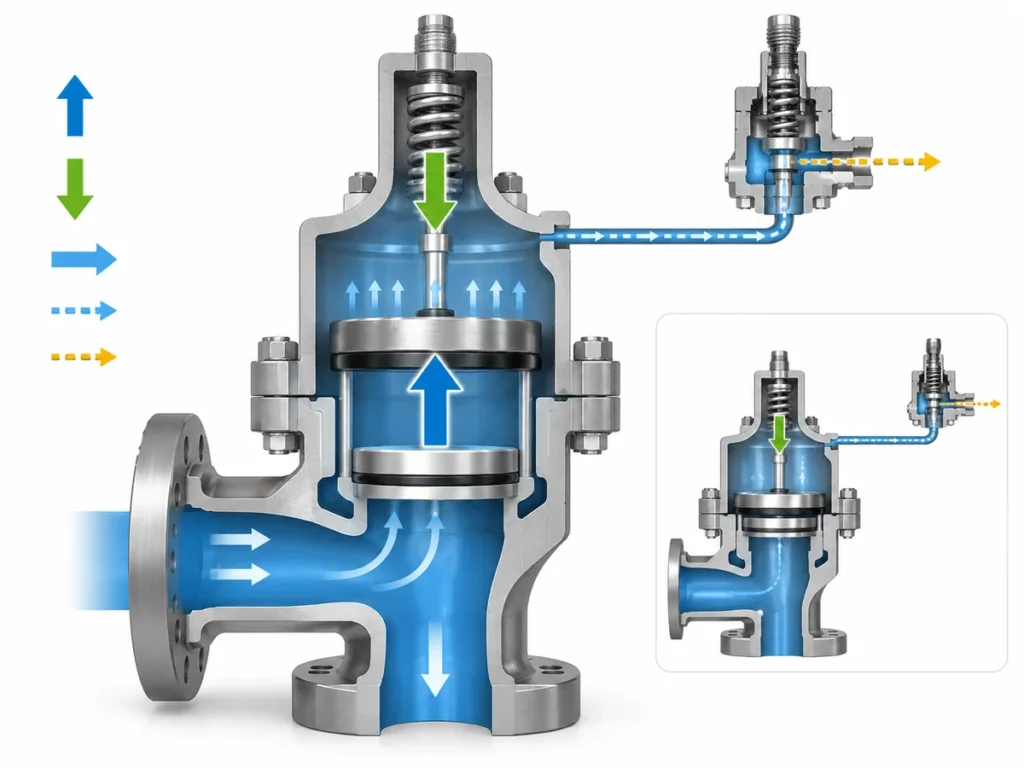
A pilot operated safety valve should not be maintained as if the pilot were simply an accessory bolted onto the main valve. The pilot, filters, sensing or supply connections, seals and main valve form a control system. Contamination, leakage, restriction or an incorrectly restored connection in that control path can matter even when the main valve body itself appears serviceable.
The second maintenance mistake is treating every post-maintenance “test” as equivalent. A pilot set-pressure check, a seat-tightness test, a complete-assembly functional test and a flow-capacity test answer different questions.
This article therefore follows two rules:
- Inspect the actual pilot/control path installed on the valve.
- Match the test to the evidence you need before return to service.
This article uses pilot operated safety valve as its working term. Manufacturer and standards documentation may also use pilot-operated pressure relief valve, POSV or POSRV. If the operating sequence itself is not yet clear, see how a pilot operated safety valve works . Exact maintenance instructions for a specific valve still come from the applicable manufacturer documentation and site requirements.
Before Maintenance, Confirm the Valve Configuration and As-Found Condition
Before cleaning a filter, disconnecting tubing or replacing seals,
establish exactly which valve and pilot configuration you are working on.
Pilot-operated designs can differ in how system pressure reaches the
pilot, whether sensing is integral or remote, how control or dome pressure
is connected, and which components are serviced or tested separately.
A maintenance step that is valid for one arrangement should not
automatically be transferred to another.
Start by confirming:
- valve and pilot identification;
- the applicable manufacturer maintenance instructions;
- the sensing arrangement, including remote sensing where used;
- process medium and relevant service conditions;
- why the valve was removed, inspected or opened;
- the as-found condition;
- relevant previous maintenance or test records, if available.
Work on the pressure-containing or pilot system must follow the applicable
plant and manufacturer isolation and depressurization procedures. For
example,
Anderson Greenwood Series 727 maintenance instructions
require the applicable POSRV assembly to be isolated and depressurized
before specified pilot maintenance work. That example does not create a
universal isolation sequence; the exact method remains site- and
model-specific.
Preserve the as-found condition before cleaning removes
useful evidence. A loaded filter, leakage around a pilot connection, an
incorrectly connected line or an unexpected deposit can help explain why
the assembly was not behaving as expected.
For the broader whole-valve maintenance program, inspection planning and
as-found/as-left context, see the
Safety Valve Maintenance and Inspection Guide
.
The present article stays focused on the pilot/control path and the
evidence needed after that work.
Maintenance decision: Do not diagnose the component before
confirming the configuration around it.
Inspect Filters as Part of the Pilot Control Path, Not as an Isolated Part
On pilot-operated valve designs that use a filter in the sensing or pilot
supply path, filter condition can tell you more than whether the filter
itself needs attention.
A filter is intended to limit contamination reaching downstream pilot
passages or related control components. If it contains significant
contamination, cleaning or replacing that one part may not close the
maintenance question.
The next question is:
Could the same contamination have affected the connected
pilot/control path?
A contaminated filter does not prove that the pilot is
blocked. It does, however, give a maintenance engineer a reason to inspect
the relevant downstream passages and connections when the amount or nature
of contamination makes further restriction credible.
The filter itself should be handled according to the applicable valve
procedure. Published manufacturer instructions do not support one
universal rule: some filter assemblies may be inspected and reused under
specified conditions, while other designs call for replacement.
Maintenance frequency has the same boundary. Filter attention should be
based on the applicable manufacturer requirements, service history and
contamination conditions rather than an arbitrary interval applied to
every pilot-operated valve.
| Filter finding | What it should change |
|---|---|
| Clean and undamaged |
Continue the remaining required pilot-path inspection; a clean filter alone does not prove that the pilot is healthy. |
| Significant contamination |
Check the connected control path for related contamination or restriction. |
| Damaged or unacceptable under the applicable procedure | Follow the model-specific replacement requirement. |
| Repeated heavy contamination |
Review why contamination continues to reach the pilot system instead of treating each filter service as an isolated event. |
Filter condition can therefore be diagnostic evidence about the
environment seen by the pilot system, not merely a housekeeping item.
Check Sensing and Control Tubing for Restriction, Leakage and Reassembly Errors
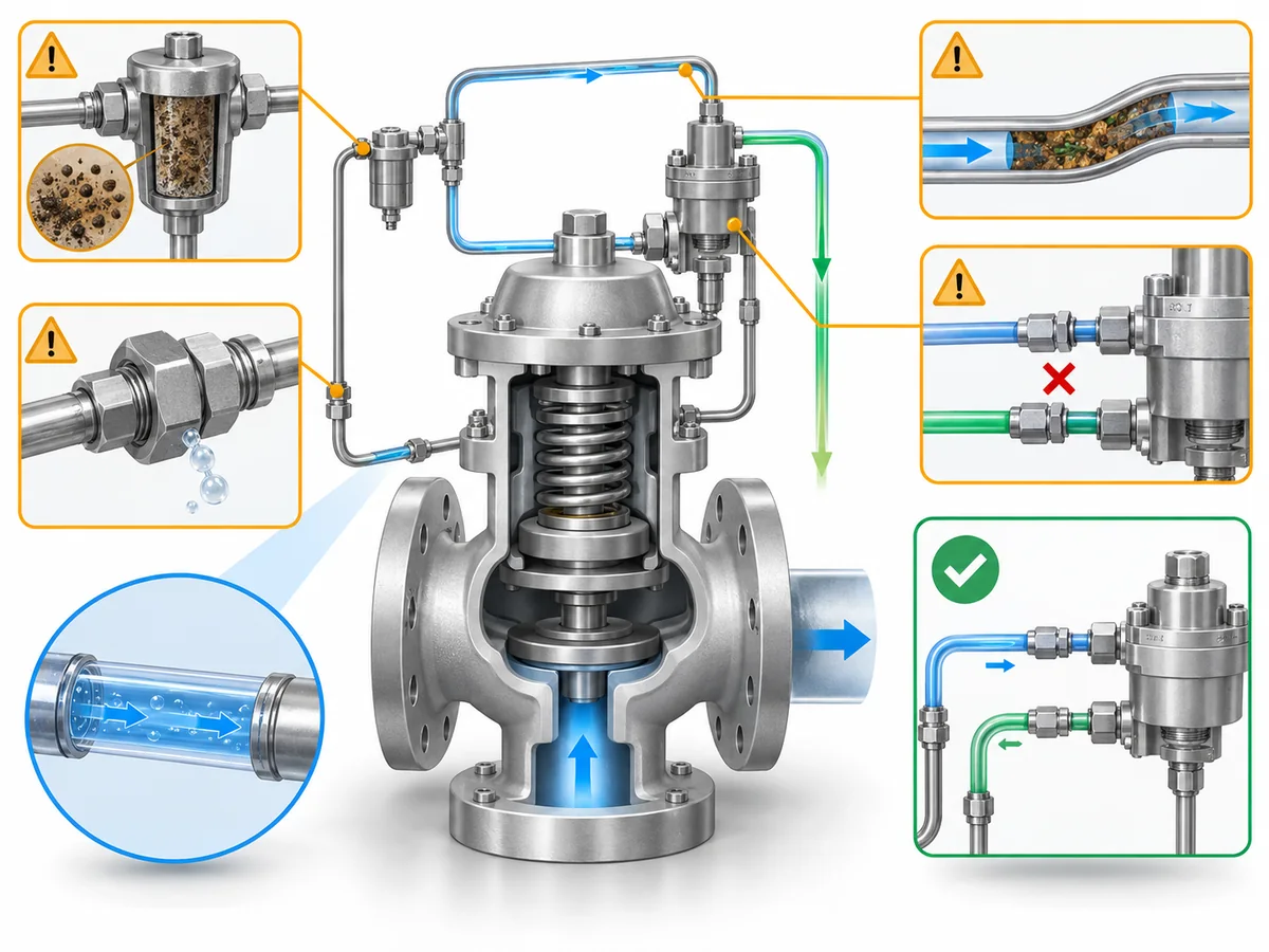
Not every small tube around a pilot-operated safety valve has the same
purpose. Depending on the design, documentation may distinguish a
pressure-sensing line, pilot supply connection, dome or control line,
remote sensing connection and other pilot tubing.
Tubing problems should therefore be separated by failure mode.
| Finding | Why it matters | Maintenance check |
|---|---|---|
| Restriction or blockage | The intended pressure signal or pilot supply path may be impeded. |
Inspect the affected passage and connected components using the applicable procedure. |
| Leakage | Pressure integrity in the sensing or control path may be lost. |
Identify the leaking connection or component and verify the restored assembly. |
| Kink, corrosion or mechanical damage |
The flow path or mechanical integrity may no longer match the intended configuration. |
Repair or replace in accordance with approved documentation. |
| Loose or incorrect reconnection |
The valve may no longer be sensing or controlling pressure through the intended path. |
Compare routing and connection points with the correct valve documentation. |
| Unverified modification to a remote-sensing line |
The sensing arrangement may no longer match the engineered configuration. |
Refer the arrangement for engineering or manufacturer review. |
The distinction between restriction and
leakage matters. A restricted path can interfere with
pressure communication through that path. A leaking connection presents a
different problem: loss of pressure integrity. The inspection and
corrective action are not interchangeable.
Remote sensing adds another boundary. Manufacturer documentation shows
that remote-sensing arrangements can depend on the intended connection
point and design-specific line geometry. Those details should not be
copied from one valve family to another.
Maintenance rule: Do not shorten, resize, reroute or
reconnect a sensing line merely because the new arrangement physically
fits. Restore the approved configuration or obtain engineering
confirmation.
A tube can look physically sound yet still be wrong because it has been
connected to the wrong point or restored differently from the approved
arrangement.
For maintenance closeout, “the tubing looks fine” is weaker evidence than
confirming that the correct pressure path has been restored and
checked for relevant restriction and leakage under the applicable
maintenance procedure.
Evaluate Seals by Location, Condition and Service Compatibility
A seal decision should not begin and end with, “Does this O-ring look
damaged?”
Pilot-operated valves can contain several seals in different functions,
and manufacturer repair instructions do not necessarily treat every
sealing component the same way. Some soft goods may be mandatory
replacement items under a particular overhaul procedure; another component
may have a different inspection or replacement rule.
Two generic shortcuts should therefore be avoided:
Reuse every seal that still looks good.
and
Replace every seal on every pilot-operated valve whenever the valve is opened.
Instead, separate four questions.
1. Which seal is it?
Identify the location and function of the part. A pilot seal, main-valve
sealing element and connection seal should not automatically inherit the
same maintenance rule.
2. Is the part and material correct?
Pilot-operated valve families can use different soft-goods materials for
different configurations and services. A replacement part should match
the approved valve configuration rather than merely having the same
apparent dimensions.
For deeper material-selection context, see the
safety valve material selection guide
.
3. Is its condition acceptable?
Inspect the component for the forms of damage or deterioration addressed
by the applicable manufacturer procedure. Appearance is useful evidence
of physical condition, but it does not establish material identity or
service compatibility.
4. Does the applicable procedure permit reuse?
This is separate from appearance. If the manufacturer procedure requires
replacement of that component during the applicable service operation, an
apparently intact seal is not evidence for ignoring the requirement.
The same distinction matters during procurement. A “similar” elastomer is
not automatically an acceptable substitute simply because it fits.
Seal decision sequence:
identity → material/configuration → condition → permitted
reuse/replacement → post-assembly verification.
Match the Functional Test to What You Need to Prove
A post-maintenance test is only as broad as its test scope.
Instead of asking only, “Did the valve pass?” ask:
Which test was performed, which variable or function did it verify, and
what remains untested?
For standards context,
API RP 576
covers inspection and repair of pressure-relieving devices including
pilot-operated pressure relief valves;
API 527
addresses seat tightness; and
ASME PTC 25
distinguishes pressure-relief-device test purposes including
flow-capacity testing from other testing activities.
A broader standards overview is available in the
safety valve standards guide
.
Those are not interchangeable forms of evidence.
| Check or test | What the result can support | What it does not automatically prove |
|---|---|---|
| Visual inspection | Visible condition, configuration and assembly observations | Set pressure, seat tightness or rated capacity |
| Pilot/set-pressure verification |
Pilot actuation or set-pressure behavior under the approved test method |
Rated flow capacity or complete installed-system acceptance |
| Seat-tightness test | Leakage performance under the applicable test basis | Complete pilot/main-valve functional performance |
| Complete-assembly functional test |
Defined operation and integrity of the assembled pilot/main valve under that procedure |
Certified flow capacity unless capacity is actually tested |
| Flow-capacity test | Flow capability under defined test conditions | Correct installation or suitability of every field-system detail |
Pilot Set-Pressure or Pilot-Function Verification
On applicable designs, a field test connection can provide a way to
verify pilot or set-pressure behavior.
That can be useful without proving everything about the assembled valve.
Some manufacturer procedures distinguish pilot-oriented artificial
actuation from actual main-valve operation. A valid pilot test can
therefore confirm the variable it was designed to check while leaving
other main-valve characteristics outside the evidence.
The same boundary applies to characteristics such as blowdown when the
test method does not fully exercise the main valve.
A useful record is not simply “Pilot test: PASS.” Record what pilot
function was verified and which required valve functions remain subject
to another acceptance basis.
Seat-Tightness and Leakage Testing
Seat-tightness testing answers the leakage question.
API 527 is specifically concerned with determining the seat tightness of
pressure relief valves within its scope, including pilot-operated designs.
A result under the applicable API 527 test basis therefore supports a
seat-leakage conclusion.
It does not automatically support the broader statement:
The entire valve has been functionally verified.
Seat tightness is one evidence category.
Complete-Valve Functional Verification
For some pilot-operated valve designs, manufacturer procedures separately
test the assembled pilot and main valve after maintenance. Such testing
can evaluate defined pilot/main-valve interaction and can include leakage
checks at relevant assembled connections.
That is broader than a pilot-only set-pressure check. It is still not
automatically a flow-capacity test.
Evidence rule: A complete-assembly functional test proves
the functions included in that approved procedure—not every
characteristic of the installed relief system.
What a Field or Functional Test Does Not Prove
The largest post-maintenance interpretation error is to expand a narrow
PASS result beyond the question that was tested.
- Pilot set-pressure verification ≠ rated capacity evidence.
- Seat-tightness PASS ≠ complete functional proof.
-
Complete-assembly functional test ≠ flow-capacity certification.
-
Bench or field valve test ≠ proof that the entire installed relief
system is correctly sized and arranged.
For maintenance records and engineering review, document enough
information to answer:
- What test was performed?
- What valve/pilot configuration was tested?
- What variable or function was evaluated?
- What acceptance basis was used?
- What did the test not evaluate?
- Does another maintenance question still remain open?
That makes the test result usable evidence instead of a generic “PASS”
label.
Decide Whether the Valve Is Ready to Return to Service
Reassembly is not the same as maintenance closure.
The return-to-service decision should combine:
- what was found;
- what was corrected;
- whether the pilot/control path was restored;
- whether parts and seals were verified;
- which tests were performed;
- what those tests actually established;
- whether any relevant question remains unresolved.
The PROCEED / HOLD / ESCALATE labels below are an
engineering screening framework used in this article. They are not API,
ASME, ISO or regulatory classifications and do not replace the valve
owner’s, manufacturer’s or applicable jurisdictional acceptance process.
| Screening outcome | Use it when |
|---|---|
| PROCEED |
The applicable maintenance scope is complete, the approved configuration is restored, parts/materials required by that scope are verified, and the required post-maintenance checks provide acceptable evidence for the questions they were intended to answer. |
| HOLD |
Relevant contamination, blockage, leakage, incorrect configuration, uncertain seal identity, failed test response or another unresolved maintenance condition remains. |
| ESCALATE |
The correct configuration cannot be established, repeated contamination may warrant review for a broader application or system cause, test behavior conflicts with expected valve response, or the next step requires engineering/manufacturer input outside the validated maintenance scope. |
Before closeout, ask:
-
Has a contaminated filter triggered the necessary inspection of the
connected pilot path? -
Have sensing, supply and control connections been checked for relevant
restriction and leakage and restored to the approved configuration? -
Are replacement or retained seals correct for the applicable valve
configuration and maintenance procedure? -
Did the test actually examine the function that the maintenance work
could have affected? - Is each PASS result being used only within the scope of that test?
-
Does any unresolved condition still require engineering, manufacturer
or owner review?
A useful maintenance handoff contains more than “valve failed” or “valve
repaired.”
Provide, where available:
- valve and pilot identification;
- relevant service conditions;
- as-found observations;
- filter and tubing findings;
- components replaced or retained;
- seal/soft-goods identification relevant to the work;
- tests performed;
- test results and acceptance basis;
- the specific unresolved question if engineering review is still required.
That information helps the next reviewer distinguish a component
maintenance problem from a configuration, service or wider application
issue.
Closeout principle: Maintenance is not complete merely
because the last part has been reassembled. It is complete when the
relevant maintenance question has been answered by evidence appropriate
to that question.