Oil & Gas Safety Valves for Critical Pressure Relief Systems
Oil and gas safety valves protect process equipment from overpressure in upstream production, gas processing, pipeline stations, refinery units, LNG service and LPG storage. A correct PSV or PRV is selected from the relief case, medium phase, set pressure, relieving capacity, back pressure, temperature, material compatibility and project documentation requirements—not from valve size alone.
Where Safety Valves Are Used in Oil & Gas Facilities
Oil and gas pressure relief applications are defined by the protected system and the credible overpressure source. The same facility may require different safety valve configurations for gas, liquid, two-phase, cryogenic, corrosive, high-pressure and high-temperature duties.
Upstream Production
Used on production separators, test separators, heater treaters, knock-out drums and wellhead packages. Typical checks include blocked outlet, fire exposure, wet gas, condensate carryover and corrosion risk.
Gas Processing Plants
Used on absorbers, contactors, scrubbers, dehydration systems, filters and process vessels. Material selection should consider H₂S, CO₂, water content, chloride exposure and sour service requirements.
Compression & Pipeline Stations
Used on compressor discharge lines, aftercoolers, scrubbers, metering skids, pig launchers and receivers. Vibration, pulsation, transient pressure and discharge back pressure must be reviewed.
Refinery Process Units
Used on pressure vessels, columns, drums, heat exchangers, fired heater systems and utility steam interfaces. Relief cases may include blocked outlet, fire case, tube rupture and control valve failure.
LNG & Cryogenic Service
Used on LNG transfer lines, boil-off gas systems, cryogenic packages and low-temperature piping. LNG is commonly handled near -260°F / -162°C, so material toughness and thermal contraction must be checked.
LPG Storage & Loading
Used on LPG bullets, spheres, loading skids, transfer lines and vapor return systems. Fire exposure, vapor pressure, discharge direction and certification documents are usually central to selection.
The First Engineering Question: Why Will the Pressure Rise?
The safety valve must be sized for the governing overpressure case. A vessel may have several credible cases, and each case can produce a different required relieving capacity.
Blocked Outlet
Downstream flow is restricted while upstream inflow continues. Common on separators, filters, process vessels, metering skids and refinery equipment. Required data include maximum credible inflow, fluid phase, set pressure and discharge condition.
External Fire Exposure
Fire exposure can vaporize liquid contents and increase vessel pressure. This case is common for hydrocarbon liquid vessels, LPG storage and refinery equipment. Review wetted surface, fluid properties, relief load and flare capacity.
Thermal Expansion
Liquid trapped between closed valves can expand as temperature rises. Thermal relief valves are often smaller than process PSVs, but incorrect set pressure or blocked discharge can still create equipment risk.
Heat Exchanger Tube Rupture
A high-pressure side can expose a lower-pressure side to overpressure. The evaluation should include pressure difference, exchanger layout, fluid phase, transient flow and downstream relief path.
Compressor or Control Failure
Compressor upset, regulator malfunction or control valve failure may cause rapid pressure rise. Vibration, pulsation, chatter risk, inlet pressure loss and discharge back pressure should be checked together.
Engineering Application Cases with Typical RFQ Data
The following cases show how oil and gas safety valve requirements are usually described before model selection. Final valve sizing must be confirmed against the project datasheet, applicable code and verified relief calculation.
Case 1: Upstream Gas Separator PSV
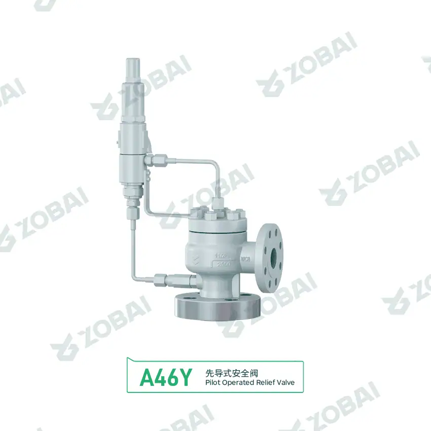
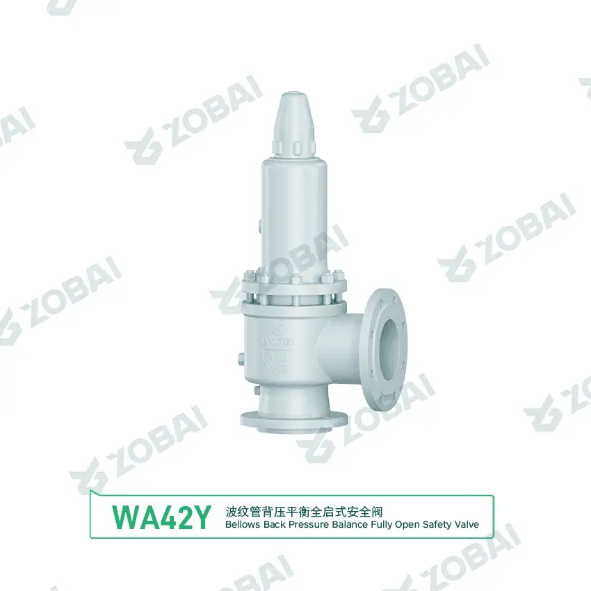
Blocked OutletFor this duty, the first decision is whether the back pressure is acceptable for a conventional spring-loaded valve. If back pressure is high or variable, a bellows balanced design or pilot operated design may be reviewed. The valve should not be selected only from separator nozzle size.
Case 2: Compressor Discharge Safety Valve
High Pressure GasCompressor applications require special attention to valve stability. Oversizing, long inlet piping or high inlet pressure loss can increase chatter risk. For clean gas with close operating pressure, pilot operated safety valves may be considered after checking gas cleanliness and maintenance access.
Case 3: LNG Transfer Line Thermal Relief
Cryogenic ServiceLNG service is not a standard ambient-temperature application. Material toughness, thermal contraction, seat leakage and safe discharge destination should be confirmed before quotation. Thermal relief valves may be compact, but the service condition is severe.
Case 4: LPG Storage Vessel Fire Case PSV
Fire ExposureLPG fire-case relief can require a significantly different capacity than normal operating relief. The RFQ should include storage condition, protected volume, set pressure, required capacity basis and discharge arrangement.
Case 5: Refinery Heat Exchanger Tube Rupture
Tube RuptureTube rupture is often missed when users only request a replacement valve by size. The relief scenario can be much more severe than a simple blocked outlet case and should be reviewed with process data.
Case 6: Sour Gas Processing Vessel
Corrosive ServiceSour gas applications should not be treated as clean natural gas service. Material selection should cover wetted parts and internal components, not only the valve body. Documentation requirements should be confirmed at RFQ stage.
Oil & Gas Safety Valve Data Matrix
| Service | Typical Medium | Common Temperature Range | Common Pressure Concern | Required Engineering Check | Risk if Missed |
|---|---|---|---|---|---|
| Natural gas processing | Dry gas, wet gas, sour gas | Ambient to elevated process temperature | High pressure, flare back pressure | Gas properties, H₂S / CO₂ content, capacity, back pressure | Wrong material, chatter, leakage or capacity loss |
| LNG transfer | LNG, boil-off gas | Approx. -162°C / -260°F for LNG | Thermal relief, vapor generation | Low-temperature material, seat behavior, discharge safety | Embrittlement, leakage or unsafe venting |
| LPG storage | Propane, butane, LPG mixture | Ambient, saturated liquid-vapor service | Fire exposure, vapor pressure | Fire-case capacity, discharge direction, certification documents | Undersized relief capacity during fire case |
| Refinery hydrocarbon unit | Hydrocarbon vapor, liquid, steam, hot oil | Ambient to high temperature | Blocked outlet, tube rupture, control failure | Relief case analysis, temperature rating, material compatibility | Generic PSV selected without governing case |
| Compressor discharge | Natural gas, process gas, fuel gas | Elevated discharge temperature | Rapid pressure rise, pulsation | Inlet loss, vibration, chatter, certified flow capacity | Unstable opening, seat damage or repeated leakage |
| Pipeline station | Natural gas, crude oil, liquid hydrocarbons | Ambient or site-dependent | Thermal expansion, transient pressure | Isolation condition, trapped liquid, set pressure and discharge path | Overpressure between closed valves |
How to Specify an Oil & Gas Safety Valve Correctly
1. Define the protected equipment
Identify whether the valve protects a vessel, separator, compressor, exchanger, pipeline section, storage vessel, loading skid or cryogenic line. The equipment defines the pressure boundary, code basis and connection requirement.
2. Confirm the governing relief case
The governing case may be blocked outlet, fire exposure, thermal expansion, tube rupture, compressor upset or control valve failure. Capacity must be based on the controlling scenario, not the nominal pipe size.
3. Check medium and phase
Gas, vapor, liquid and two-phase flow require different sizing data. Natural gas, wet gas, sour gas, LNG, LPG, crude oil, condensate and steam should not be treated as the same service.
4. Review back pressure
If the valve discharges into a flare or closed vent system, back pressure can affect capacity and stability. Conventional, bellows balanced and pilot operated configurations should be reviewed against actual back pressure.
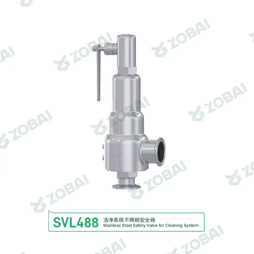
5. Select material for real operating conditions
H₂S, CO₂, chlorides, water content, cryogenic temperature, high temperature and offshore exposure can affect body, trim, spring, bellows and seal selection.
6. Confirm testing and documentation
Oil and gas projects commonly require datasheets, sizing basis, set pressure calibration, material certificates, pressure test reports, seat tightness test records, drawings and nameplate data.
Safety Valve Types Commonly Reviewed for Oil & Gas Projects
Oil and gas service may require different valve configurations depending on back pressure, phase behavior, pressure class, temperature, corrosion risk and maintenance strategy.
The Safety Valve Must Be Reviewed With Its Piping System
Why piping conditions decide valve performance
A safety valve is installed as part of a relief system. Excessive inlet pressure loss, long inlet lines, unsupported discharge piping, liquid pockets, vibration and high back pressure can reduce capacity or cause unstable operation.
For oil and gas facilities, discharge piping is especially important because many valves relieve into flare headers, closed vent systems or elevated atmospheric vents. The discharge arrangement should protect operators, equipment and downstream systems.
Field installation checks
- Install the valve close to the protected equipment where practical.
- Avoid excessive inlet pressure loss before the valve inlet.
- Support discharge piping without loading the valve body.
- Check liquid pockets and drainage in outlet piping.
- Confirm back pressure for flare or vent header systems.
- Leave enough space for inspection, lifting device access and maintenance.
Standards and Documents to Confirm Before Ordering
Common standard references
Oil and gas safety valve specifications may reference API, ASME, ISO, EN, GB or owner standards depending on the region, equipment type and project requirement. The applicable standard should be confirmed before quotation.
- API 520 Safety Valve Sizing for sizing and selection reference of pressure-relieving devices.
- API 521 Pressure Relief Systems for pressure-relieving and depressuring system review.
- API 526 Flanged Safety Valves when flanged steel pressure relief valve dimensions, ratings and orifice designations are specified.
- API 527 Seat Tightness Test when seat leakage testing is required.
- ASME Safety Valve Standards and ISO 4126 Safety Valve Standards where pressure vessel, boiler or product-standard requirements apply.
- ANSI/NACE MR0175 / ISO 15156 when sour service material selection is required.
Typical document package
Documentation should be agreed before production, especially for refinery, LNG, LPG, offshore, gas processing and pipeline station projects.
- Technical datasheet with model, size, orifice, set pressure and connection.
- Sizing calculation or relieving capacity confirmation.
- Set pressure calibration record.
- Pressure test report and seat tightness test report when required.
- Material certificate for pressure-retaining parts when specified.
- General arrangement drawing, dimension and weight.
- Nameplate, tag number and project marking confirmation.
Oil & Gas Safety Valve RFQ Data Checklist
| Required Data | Why It Matters | Example Input |
|---|---|---|
| Protected equipment | Defines the pressure protection target and code basis. | Separator, compressor discharge, heat exchanger, LPG tank |
| Relief scenario | Determines the governing required relieving capacity. | Blocked outlet, fire case, thermal expansion, tube rupture |
| Medium and phase | Affects sizing method, material and seat design. | Natural gas, sour gas, LNG, LPG, crude oil, two-phase flow |
| Set pressure | Defines valve opening pressure. | 10 bar, 150 psi, 25 MPa |
| Operating pressure | Confirms operating margin and leakage risk. | Normal and maximum operating pressure |
| Required relieving capacity | Confirms whether the selected valve can protect the system. | kg/h, Nm³/h, SCFM, t/h, GPM |
| Relieving temperature | Affects material, spring, seal and pressure rating. | -196°C, ambient, 250°C, 450°C |
| Back pressure | Influences valve stability, capacity and configuration. | Atmospheric discharge, flare header, variable back pressure |
| Material requirement | Prevents corrosion, embrittlement and compatibility failure. | Carbon steel, stainless steel, alloy, low-temperature material |
| Connection and rating | Ensures mechanical compatibility with piping. | RF flange, RTJ flange, NPT, BW, Class 150–2500 |
| Applicable standard | Defines sizing, testing and documentation expectations. | API, ASME, ISO, EN, GB or owner specification |
| Existing valve data | Helps replacement projects avoid wrong assumptions. | Nameplate photo, old datasheet, drawing, tag number |
Final selection must be confirmed by project datasheet, process conditions, applicable code, verified sizing basis and engineering review.
Common Oil & Gas Safety Valve Selection Mistakes
Buying by inlet size only
Inlet size does not confirm relieving capacity. A valve that fits the nozzle can still be undersized if the governing relief case requires a larger certified capacity.
Ignoring flare header back pressure
Back pressure can affect opening, capacity and stability. If the valve discharges to a flare or closed vent system, back pressure should be reviewed before choosing the valve configuration.
Treating sour gas as clean gas
H₂S, CO₂, water and chlorides can change material requirements. The body, trim, spring, bellows and seals should be checked for real process conditions.
Missing thermal relief cases
Liquid trapped between closed valves can overpressure when heated. Thermal relief is especially important for isolated pipeline sections, loading lines and cryogenic systems.
Oversizing compressor PSVs
Oversizing can contribute to chatter and seat damage. Compressor service needs inlet pressure loss, vibration, pulsation and actual required capacity review.
Replacing by nameplate photo alone
A nameplate helps, but replacement should also confirm relief case, capacity, orifice, set pressure, back pressure, medium, material and documentation requirements.
Continue Your Oil & Gas Pressure Relief Review
These related engineering pages help move from industry application to detailed safety valve selection, sizing, operating condition and medium-specific review.
Official References for Oil & Gas Pressure Relief Review
Use these external references as authoritative starting points when confirming project standards, pressure vessel code basis, relief system design, seat tightness, sour service materials and pressure relief device certification.
Oil & Gas Safety Valve FAQ
Prepare a Complete Oil & Gas PSV Datasheet Before Quotation
Send the protected equipment, relief scenario, medium, set pressure, operating pressure, required capacity, temperature, back pressure, material requirement, connection standard and required documents. A complete datasheet helps avoid unsafe assumptions and speeds up engineering review.