Dual Safety Valve Systems • Online Maintenance & Continuous Protection
Changeover Safety Valves Manufacturer for Dual PSV Systems and Online Maintenance
Changeover safety valves are dual pressure relief valve assemblies designed to maintain overpressure protection while one safety valve is inspected, tested, repaired or recalibrated. They are commonly used where continuous operation is required and shutdown for safety valve maintenance is not practical.
ZOBAI supplies changeover safety valves, PRV changeover valves, dual safety valve assemblies and safety valve manifolds with engineering support for set pressure, certified relieving capacity, changeover port area, inlet pressure loss, locking design, duty standby logic, outlet piping, materials and project documentation.
System Type: Dual PSV / Changeover Valve / Safety Valve Manifold
Service: Gas/ Refrigerant/ Chemical / Liquid / VaporSteam
Key Checks: Capacity / Flow Area / Locking / Inlet Loss / Outlet System
Applications: Refrigeration / Chemical Plant / Gas Skid / Pressure Vessel
Options: Lockable Handle / Position Indicator / Flanged / Threaded / Welded
Docs: Datasheet / Capacity Data / Test Report / Calibration Record
Changeover safety valve selection should be confirmed against the protected equipment, medium, set pressure, operating pressure, required relieving capacity, duty standby philosophy, changeover valve flow area, inlet pressure loss, locking method, material, outlet piping and applicable code requirements.
Safety Valve Categories
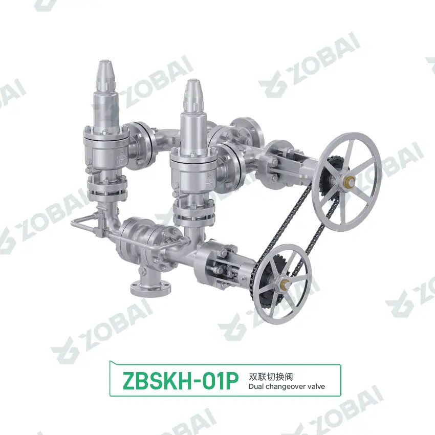
ZBSKH Stainless Steel Changeover Valve System
Changeover Safety Valves for Continuous Pressure Protection and Online Maintenance
Changeover safety valves are dual pressure relief valve assemblies designed to keep equipment protected while one safety valve is removed, inspected, tested or maintained. A changeover valve, diverter valve or transfer valve directs the protected equipment to one active safety valve while the standby valve remains isolated or ready for switching.
Why changeover systems are used
In continuous process plants, refrigeration systems, chemical units, gas skids and storage systems, shutting down equipment only to remove one safety valve may be costly or impractical. A changeover safety valve system allows planned maintenance while maintaining overpressure protection through the online valve.
The engineering risk is not the idea of redundancy itself. The risk is a poorly designed changeover system that can accidentally isolate both valves, reduce inlet flow area, create excessive pressure drop, confuse the operator, or allow the wrong valve to remain in service after maintenance. A proper design should make the active relief path clear, full-capacity and lockable.
Selection boundary
Changeover safety valve systems are commonly used where continuous protection and service continuity matter. Typical applications include chemical reactors, pressure vessels, refrigeration systems, LNG or gas skids, storage tanks, process headers and systems requiring periodic safety valve recalibration.
A changeover system should be designed so maintenance access does not compromise the required relieving capacity of the protected equipment, and so no normal handle position can isolate every qualified relief path.
How a Changeover Safety Valve System Works
A changeover safety valve system normally uses two safety valves installed on a common inlet arrangement with a changeover valve between the protected equipment and the relief valves. During operation, the changeover valve connects the equipment to one active safety valve. When maintenance is needed, the operator switches the flow path to the standby valve, verifies the active path, locks the changeover position and removes the offline valve for inspection or recalibration.
Normal Duty
One safety valve is online and protects the vessel, tank, pipeline or process equipment.
Switching
The changeover valve redirects the relief path from the duty valve to the standby valve.
Locking
The selected position is locked or controlled so the active relief path cannot be accidentally changed.
Maintenance
The isolated safety valve can be removed, tested, repaired and reinstalled without stopping the whole system.
Key Design Points in Changeover Safety Valves
Changeover systems must be reviewed as a complete pressure relief arrangement, not just as two safety valves. The changeover valve, inlet bore, outlet routing, locking device, operator procedure and test documentation all affect whether the protected equipment remains safe.
Duty and Standby Safety Valve Arrangement
A changeover assembly usually has one valve online and one valve on standby. Duty and standby valves are commonly selected to the same approved service basis, but the project must confirm each valve’s set pressure, certified capacity and suitability. The active path must independently provide the required protection unless the approved relief philosophy explicitly uses another arrangement.
For critical service, nameplate data, tag numbers, flow direction marks and operating instructions should be clear enough for field operators to avoid switching errors.
Full Bore and Inlet Pressure Loss
The changeover valve should not create excessive inlet restriction. If the inlet flow path is too small or has sharp turns, the active safety valve may chatter or fail to pass the required relieving capacity.
The inlet path, changeover valve port area, fittings and nozzle connection should be reviewed together, especially for gas, steam and high-flow relief cases.
Locking, Position Indication and Operating Control
A safe changeover system should prevent accidental isolation of both relief valves. Locking devices, mechanical stops, position indicators and documented switching procedures help reduce human error.
For regulated or high-risk applications, valve position control and maintenance records may be as important as the mechanical design itself.
Online Testing, Removal and Recalibration
The main benefit of a changeover safety valve system is maintenance continuity. One valve can be removed for calibration, seat repair, cleaning or certification while the other valve remains available for protection.
After maintenance, the reinstalled valve should be checked for set pressure, seat tightness, nameplate match, seal integrity and correct isolation status.
Quick Changeover Safety Valve Fit Check
Use this quick guide to identify what should be reviewed before quotation. It does not replace relief sizing, project code review or site operating procedure approval.
Select your application condition
Click one condition below to see the engineering checks that matter most.
Parameters That Decide Whether a Changeover Safety Valve System Is Suitable
Changeover Safety Valve System vs Single Safety Valve Installation
| Item | Changeover Safety Valve System | Single Safety Valve Installation |
|---|---|---|
| Main purpose | Allows online maintenance while keeping one safety valve in service. | Provides direct overpressure protection with a simpler arrangement. |
| Typical arrangement | Two safety valves with a changeover valve, diverter valve or manifold. | One safety valve connected directly to protected equipment. |
| Maintenance impact | One valve can be removed while the other remains online. | Equipment may need shutdown or temporary protection for valve removal. |
| Design complexity | Higher. Requires flow path, locking, inlet loss and procedure review. | Lower. Fewer isolation and switching risks. |
| Main risk | Accidental isolation, restricted flow path or wrong valve left online. | Lack of protection during removal or delayed maintenance. |
| Best suited for | Continuous process, refrigeration, chemical, gas skid and critical equipment. | Simple equipment where shutdown for PSV maintenance is acceptable. |
Where Changeover Safety Valves Are Used
Continuous chemical process equipment
Chemical reactors, pressure vessels and process headers may require safety valve maintenance without stopping production. Changeover assemblies allow one valve to remain online while the other is inspected.
Refrigeration and low-temperature systems
Refrigeration systems often use dual relief valve arrangements so one pressure relief valve can be serviced while the system remains protected. Material, refrigerant compatibility and discharge routing should be checked.
Gas skids and pressure packages
Gas skids, compressor packages and pressure reduction stations may use changeover valves to support periodic PSV testing. Capacity, inlet pressure loss and outlet back pressure should be reviewed.
Storage tanks and process headers
Tanks and headers that require continuous pressure protection may use changeover assemblies for maintenance continuity, especially where shutdown or depressurization is costly.
Changeover Safety Valve Selection Table
| Application | Common Requirement | Recommended Review | Key Engineering Check | Main Risk |
|---|---|---|---|---|
| Continuous process vessel | Online PSV maintenance | Dual safety valve with lockable changeover valve | Capacity, set pressure, flow path, locking and procedure | Both valves isolated by mistake |
| Refrigeration system | Relief valve replacement without shutdown | Changeover valve for dual relief valves | Refrigerant compatibility, set pressure and discharge routing | Wrong standby valve or blocked relief path |
| Gas skid | Periodic testing with system online | PRV changeover manifold | Gas capacity, inlet pressure loss, outlet header and valve tagging | Chatter from restricted inlet path |
| Chemical service | Maintenance continuity in corrosive media | Corrosion-resistant changeover safety valve system | Material, seat, gasket, flushing and isolation procedure | Corrosion, leakage or sticking during switching |
| Steam or hot service | Safe maintenance under hot conditions | High-temperature compatible changeover assembly | Steam capacity, temperature, drain, thermal expansion and safe discharge | Thermal stress or unsafe removal condition |
| Replacement project | Match existing dual relief arrangement | Nameplate, drawing and switching sequence review | Set pressure, capacity, valve orientation, porting and lock status | Replacing without understanding flow path |
This table is for preliminary engineering screening. Final selection must be confirmed against the protected equipment, medium, set pressure, required relieving capacity, changeover valve port area, pressure drop, outlet system, material, locking method and applicable project standards.
Common Engineering Mistakes to Avoid
Allowing both safety valves to be isolated
The most serious changeover system error is a switching or isolation arrangement that can leave the protected equipment without an active relief path.
Ignoring changeover valve port restriction
A changeover valve can create a smaller flow path than the safety valve inlet. This may increase inlet loss, reduce stability and cause chatter during relief.
Poor tagging and unclear switching procedure
Operators must know which valve is online, which valve is isolated and which position is locked. Poor labels and unclear procedures can defeat a good mechanical design.
Changeover Safety Valve Troubleshooting Table
| Symptom | Possible Cause | Engineering Check | Corrective Action |
|---|---|---|---|
| Unclear online valve status | Poor position indication, missing tags or undocumented switching | Check valve handle position, lock status, tags and operating log | Add clear indication, locking procedure and switching record |
| Safety valve chatters during relief | Restricted changeover port, long inlet path, elbows or excessive inlet loss | Review flow area, inlet pressure loss and relief capacity | Increase port area, revise manifold layout or recalculate sizing |
| Standby valve fails inspection | Outdated calibration, wrong set pressure, seat leakage or wrong material | Check nameplate, calibration record, seat tightness and service data | Repair, recalibrate, reseal and update maintenance records |
| Leakage at changeover valve | Seat wear, corrosion, gasket damage, thermal cycling or debris | Inspect seat, seals, body material, operating cycles and medium compatibility | Repair or replace seals, clean internals and review material selection |
| Unable to remove offline valve safely | Improper isolation, trapped pressure, poor drain/vent provision or hot service | Check isolation status, bleed point, pressure gauge and temperature | Add safe depressurization steps, vents, drains and lockout procedure |
Standards and Documents to Confirm Before Purchase
Standards to review
Changeover safety valve specifications may reference pressure relief valve sizing standards, pressure vessel requirements, installation guidance, maintenance practices, seat tightness testing and project-specific isolation rules.
- ASME BPVC Section VIII where pressure vessel protection requirements apply.
- API 520 Part I for sizing and selection guidance where applicable.
- API 520 Part II / installation review for inlet and outlet piping guidance where applicable.
- API RP 576 for pressure-relieving-device inspection, testing, maintenance and repair practices where applicable.
- API 527 where the valve design and project specification use API 527; otherwise confirm the applicable leakage criterion.
- ISO 4126-1 where general safety valve requirements are specified.
Documents buyers often request
Documentation should be confirmed before quotation, especially for pressure vessels, refrigeration systems, chemical units, gas skids, storage systems and continuous process equipment.
- Assembly datasheet and layout drawing.
- Safety valve datasheets for duty and standby valves.
- Changeover valve porting and flow direction drawing.
- Set pressure calibration records.
- Certified relieving capacity information.
- Material certificates and pressure test reports when required.
- Switching, locking, maintenance and reinstallation procedure.
Related Pages for Changeover Safety Valve Selection
Use these internal pages to connect the changeover assembly with the correct valve type, protected equipment, installation review, sizing basis and maintenance support.
Related safety valve types
- Safety Valves for the full pressure protection product range.
- Frequent Cycling Applications for repeated valve operation, maintenance planning and reliability review.
- Dual Safety Valves for duty / standby pressure relief arrangements.
- Spring Loaded Safety Valves for direct acting relief service.
- Pilot Operated Safety Valves where clean service, tightness or operating margin requires review.
- Bellows Balanced Safety Valves for back pressure or corrosive discharge conditions.
- Pressure Relief Valves for PRV / PSV terminology and selection comparison.
Applications and service conditions
- Pressure Vessels where continuous relief protection is required.
- Skid Systems for gas packages and modular process equipment.
- Compressor Safety Valves for air, gas, CO₂ and refrigeration compressor packages.
- Chemical Processing for corrosive or continuous-process units.
- Industrial Gas for cylinder filling, pressure reduction and gas skid systems.
- LNG Safety Valves for cryogenic relief systems, low-temperature materials and gas storage applications.
- LPG Safety Valves for propane, butane, storage vessel and transfer-system protection.
- Ammonia Safety Valves for R717 refrigeration, material compatibility and safe discharge review.
- Corrosion Resistant Safety Valves where material compatibility affects the assembly.
Engineering guides
- Safety Valve Selection Guide for valve type, material, pressure and medium review.
- Safety Valve Sizing Guide for required capacity and certified relieving capacity checks.
- Safety Valve Installation Guide for inlet loss, outlet piping and isolation concerns.
- Back Pressure and Bellows for header discharge and balanced-valve review.
- Safety Valve Knowledge Center for technical articles, terminology and engineering checklists.
- Ask an Engineer for datasheet, drawing and RFQ review.
- Safety Valve Catalog PDF for downloadable product documents.
Standards pages on ZOBAI
- ASME Safety Valve Standards for boiler and pressure vessel code references.
- API 520 Safety Valve Sizing for sizing and selection language.
- API 521 Pressure Relief Systems for relief and depressuring system design context.
- API 526 Flanged Safety Valves for flanged steel PRV dimensions and ratings.
- API 527 Seat Tightness Test for leakage test specification support.
- ISO 4126 Safety Valve Standards for international safety valve requirements.
- Pressure-Temperature Ratings for material and connection limit review.
External Standards for Changeover Safety Valve Projects
These external sources are useful when the project specification requires official standard references, inspection language, pressure vessel certification or product standard confirmation.
API references
- API 520 Part I for sizing and selection of pressure-relieving devices.
- API 520 Part II, 7th Edition for pressure-relieving-device installation, inlet pressure loss and outlet piping considerations.
- API RP 576 inspection reference for pressure-relieving-device inspection, testing, maintenance and repair practices.
- API Standard 527 for seat-tightness requirements where specified for the selected pressure relief valves.
ASME, ISO and National Board references
- ASME BPVC Section XIII for overpressure-protection rules covering pressure relief devices, testing, marking, capacity certification and installation.
- ISO 4126-1 for general requirements for safety valves.
- National Board Inspection Code for inspection, repair and post-construction pressure-relief-device context.
- 46 CFR §54.15-10 as a scope-limited U.S. marine pressure-vessel example; do not apply it outside its jurisdiction without project review.
Changeover Safety Valve FAQs
These answers clarify changeover arrangements, online maintenance, isolation risks and the technical data required before quotation.
RFQ Checklist for Changeover Safety Valves
| Required Data | Why It Matters | Example Input |
|---|---|---|
| Protected equipment | Defines the relief case and operating requirement. | Pressure vessel, refrigeration receiver, reactor, gas skid, storage tank |
| Medium | Determines sizing method, material and discharge arrangement. | Gas, vapor, steam, refrigerant, liquid, chemical vapor |
| Set pressure | Defines when each safety valve opens. | 10 bar g, 150 psi, 600 psi |
| Required relieving capacity | Confirms whether the online valve can protect the equipment. | kg/h, lb/h, Nm³/h, SCFM, GPM |
| Duty / standby philosophy | Clarifies whether one valve or multiple valves are required online. | One online + one standby, two online + one spare |
| Changeover valve type | Defines switching mode and flow path. | Three-way, diverter, transfer, dual changeover assembly |
| Locking requirement | Prevents accidental isolation or wrong position. | Lockable handle, car seal, interlock, position indicator |
| Connection | Ensures installation compatibility. | Flanged, threaded, welded, sanitary, ASME Class, EN PN |
| Material requirement | Prevents corrosion, temperature or compatibility issues. | WCB, CF8M, bronze, duplex, low-temperature steel, alloy |
| Outlet system | Affects back pressure, discharge force and safe routing. | Atmospheric vent, flare header, silencer, scrubber, closed line |
| Applicable standard | Defines documentation, testing and acceptance requirements. | ASME, API, ISO, EN, GB, project specification |
| Existing drawing or nameplate | Reduces replacement selection risk. | Photo, model, set pressure, capacity, porting direction, tag numbers |
Need Help Selecting a Changeover Safety Valve System?
Send us your protected equipment, medium, set pressure, operating pressure, required relieving capacity, duty and standby philosophy, changeover valve type, connection, material requirement, locking requirement, outlet system and existing drawing. Our engineering team can review whether a changeover safety valve assembly is suitable before quotation.
Prepare these data before RFQ
TECHNICAL INSIGHTS
Insights for Safer Valve Selection
FAQ
Changeover Safety Valve FAQs for Dual PSV Systems and Online Maintenance
What is a changeover safety valve?
A changeover safety valve is a dual pressure relief valve arrangement that allows one safety valve to stay online while the other valve is isolated for inspection, testing, repair or recalibration. It is used where continuous pressure protection is required.
Why use two safety valves with a changeover valve?
Two safety valves with a changeover valve allow maintenance without leaving the protected equipment unprotected. One valve remains in service while the other can be removed or tested.
Can both safety valves be isolated at the same time?
A safe changeover system should be designed and operated so both safety valves cannot be isolated from the protected equipment at the same time. Locking, position indication, interlock or controlled procedures should be reviewed.
Does each safety valve need full relieving capacity?
In many duty standby arrangements, the online safety valve must have enough certified relieving capacity to protect the equipment by itself. The final requirement depends on the relief philosophy, code basis and project specification.
What is the main risk in a changeover safety valve system?
The main risks are accidental isolation, restricted flow area, excessive inlet pressure loss, wrong valve left online, unclear position indication and poor switching or maintenance procedure.
Can changeover safety valves be used in refrigeration systems?
Yes. Refrigeration systems often use dual relief valve changeover arrangements so one valve can be serviced while the system remains protected. Refrigerant compatibility, set pressure, low-temperature material and discharge routing should be confirmed.
What should be checked before switching a changeover safety valve?
Before switching, confirm which valve is online, which valve is isolated, whether the standby valve is calibrated, whether the flow path is open, whether the position can be locked, and whether the offline side is safely depressurized before removal.
What information is needed before requesting a changeover safety valve quotation?
Provide the protected equipment, medium, set pressure, operating pressure, required relieving capacity, duty standby philosophy, changeover valve type, connection, material requirement, locking requirement, outlet system, applicable standard, quantity and any existing drawing or nameplate.

Raymon Yu
“When a safety valve fails to pop on site, it’s rarely because someone can’t read a standard. It’s usually because critical operating parameters (like backpressure or relief temperature) were assumed instead of specified. I reviewed the key technical content on this page to keep it practical, API/ASME spec-aligned, and RFQ-ready. (We prefer assumptions for lunch choices.)”
What I work on daily: reviewing drawings and project specs, supporting engineer-to-engineer questions, resolving capacity calculations, material selection, and backpressure impacts so production and quoting stay consistent. (Yes—set pressure and seat tightness test records get plenty of attention.)