Low Lift Design • Controlled Capacity Safety Relief Valves
Low Lift Safety Valves Manufacturer for Compact and Controlled Pressure Relief
Low lift safety valves are designed with limited disc lift to provide controlled relieving capacity for compact pressure systems, water systems, air receivers, thermal relief duties, small pressure vessels and selected liquid or gas applications.
ZOBAI supplies spring loaded low lift safety valves and low lift type safety relief valves with engineering support for set pressure, required relieving capacity, medium, temperature, lift design, seat material, body material, connection standard, outlet condition and project documentation.
Valve Type: Low Lift / Spring Loaded / Compact Relief
Service: Water / Air / Liquid / Small Steam / Thermal Relief
Key Checks: Set Pressure / Capacity / Lift / Seat Tightness / Outlet Condition
Applications: Small Vessel / Compressor / Water System / Skid Equipment
Options: Threaded / Flanged / Metal Seat / Soft Seat
Docs: Datasheet / Test Report / Calibration Record / Material Certificate
Low lift safety valve selection should be confirmed against the actual medium, set pressure, operating pressure, required relieving capacity, limited lift design, temperature, material, connection, outlet condition and applicable code requirements.
Safety Valve Categories
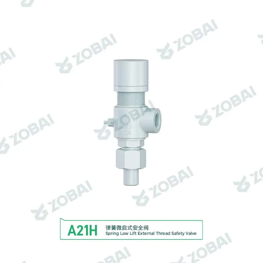
A21H DN15 Pipe Union Safety Valve
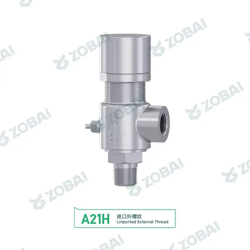
A21H DN15 Stainless Male Thread Safety Valve
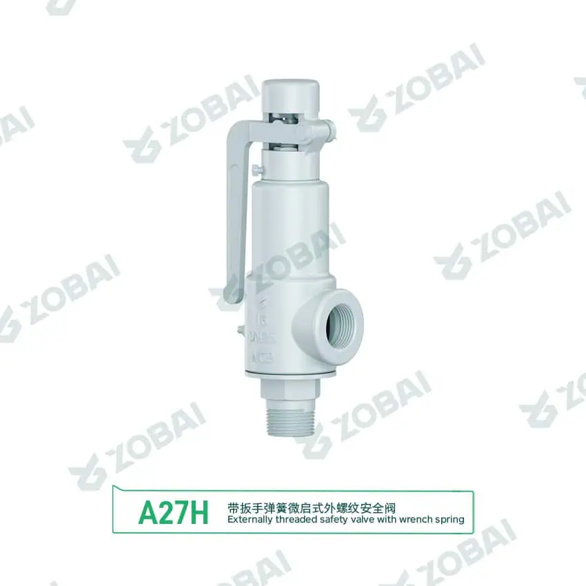
A27H DN25 WCB Threaded Safety Valve with Lever
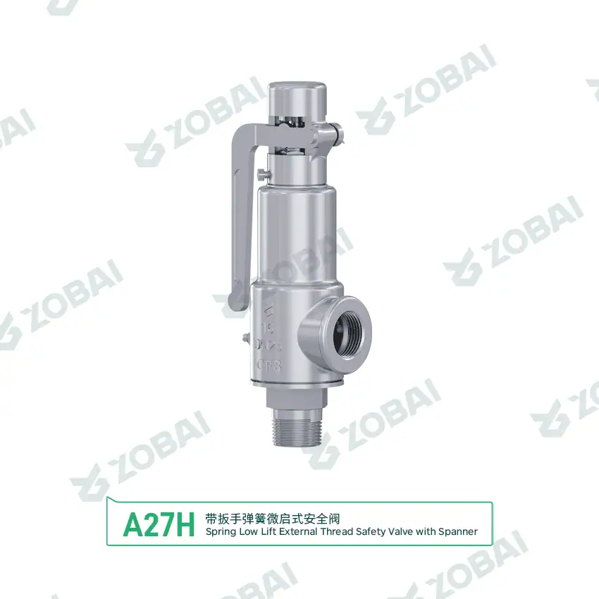
A27H DN25 Stainless Threaded Safety Valve with Lever
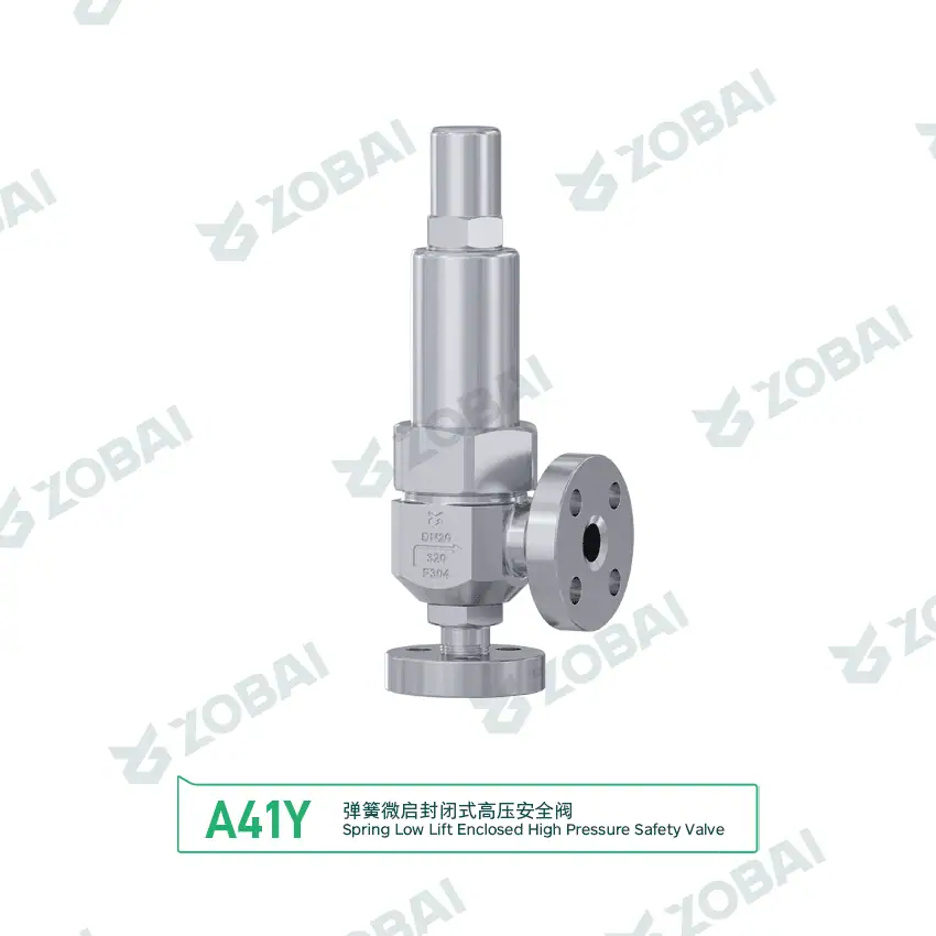
A41Y DN20 320P Flanged Safety Valve
Low Lift Safety Valves for Controlled Small-to-Medium Capacity Relief
Low lift safety valves are safety relief valves designed with a limited disc lift compared with full lift designs. They are commonly used where the required relieving capacity is moderate, the equipment is compact, the relief duty is predictable, or the system does not require the large discharge area of a full lift safety valve.
Why low lift design matters
A low lift safety valve limits the travel of the disc, which limits the effective flow area and therefore the rated capacity. This can be useful in compact equipment, small pressure vessels, utility systems, thermal relief duties, water systems, air service and selected liquid applications where over-sizing a full lift valve may create instability or unnecessary discharge.
Low lift design does not mean low importance. The valve still protects pressure equipment and must be selected by set pressure, required relieving capacity, medium, temperature, material compatibility, seat tightness, inlet pressure loss, outlet condition and applicable code.
Selection boundary
Low lift safety valves are usually considered when the relief load is not large enough to require a full lift valve, or when a compact valve with stable operation is preferred. They are not suitable for every boiler, high-capacity steam, large gas relief or severe back pressure application.
The valve should be selected only after confirming that the limited lift and rated orifice can still discharge the required relieving capacity under the specified relief case.
How a Low Lift Safety Valve Works
A low lift safety valve remains closed during normal operation. When the system pressure reaches the set pressure, the disc lifts from the seat and begins relieving pressure. Unlike full lift designs, the disc lift is limited, so the effective discharge area is smaller and the rated capacity is lower. The valve then reseats when pressure falls within the designed blowdown range.
Closed Position
The spring holds the disc against the seat while system pressure remains below the set pressure.
Initial Opening
At set pressure, the pressure force starts lifting the disc and a controlled relief path begins to open.
Limited Lift Relief
The valve reaches its designed limited lift, allowing a controlled flow rate based on the rated discharge area.
Reseating
As pressure falls, the spring closes the valve. Seat condition, blowdown and outlet condition affect leakage risk.
Key Design Points in a Low Lift Type Safety Valve
Low lift safety valve design should be reviewed through lift height, orifice area, spring range, seat geometry, guide stability and the actual relief scenario. The value of a low lift valve is not only compact size, but predictable relief performance for smaller or moderate capacity duties.
Limited Disc Lift
Low lift design limits how far the disc moves away from the seat. This reduces the effective discharge area compared with a full lift design. The benefit is a more compact and controlled relief device for smaller capacity requirements.
The limitation must be respected. If the required relieving capacity increases after a process change, the original low lift valve may no longer be sufficient.
Rated Capacity and Orifice Area
A low lift safety valve must be selected by required relieving capacity and certified flow data, not by connection size or visual appearance. The orifice and lift together determine the flow capability.
A low lift valve is often appropriate for water, air, thermal relief or compact skid systems, but high-flow steam or gas relief may require a full lift or large-orifice valve.
Seat Tightness and Reseating
Low lift valves are often used where frequent small pressure excursions or thermal expansion may occur. Seat material, operating pressure margin and cleanliness affect whether the valve reseats tightly after opening.
Dirt, sealant particles, corrosion or operating too close to set pressure can cause leakage even when the valve size is correct.
Typical Service Conditions
Low lift safety valves are commonly considered for compact equipment, water systems, air receivers, thermal relief points, small vessels, low-to-moderate capacity gas service and selected liquid relief applications.
They should be applied carefully in steam, high-temperature, high-capacity or severe back pressure systems because the limited lift may not provide enough discharge margin.
Quick Low Lift Safety Valve Fit Check
Use this quick guide to identify what should be reviewed before ordering. It does not replace sizing calculation, capacity verification or code review.
Select your main service condition
Click one condition below to see the engineering checks that matter most.
Parameters That Decide Whether a Low Lift Safety Valve Is Suitable
Low Lift Safety Valve vs Full Lift Safety Valve
| Item | Low Lift Safety Valve | Full Lift Safety Valve |
|---|---|---|
| Disc lift | Limited lift with smaller effective flow area. | Larger rated lift with higher discharge area. |
| Capacity range | Usually selected for small-to-medium relief duties. | Usually selected for higher-capacity steam, gas or vessel relief. |
| Typical service | Water, air, thermal relief, compact skids and selected liquid service. | Boiler, steam, gas, marine boiler and high-capacity applications. |
| Selection advantage | Compact design and controlled relief for moderate flow demand. | Higher capacity and rapid discharge for severe overpressure cases. |
| Main limitation | May not provide enough capacity for high relief loads. | May be oversized for small systems and create instability if misapplied. |
| Engineering check | Capacity, lift limit, seat tightness, operating margin and medium. | Capacity, blowdown, back pressure, discharge force and material. |
Where Low Lift Safety Valves Are Used
Water and thermal relief systems
Low lift safety valves are often considered for water systems, thermal expansion relief and small utility systems. Selection should confirm thermal expansion case, set pressure, seal material, discharge route and seat tightness.
Air receivers and compressor packages
Compact air systems may use low lift safety valves when the required relieving flow is moderate. Compressor capacity, vibration, operating pressure margin and outlet discharge direction should be reviewed.
Small pressure vessels and skids
Low lift designs can fit compact skids and small vessels where space is limited and relief demand is not high. The valve should still be sized against the actual credible overpressure case.
Selected liquid and utility service
For selected liquid relief duties, a low lift valve may provide controlled relief. Viscosity, temperature, seat material, discharge piping and potential fouling should be checked before final selection.
Low Lift Safety Valve Selection Table
| Service Condition | Common Requirement | Recommended Review | Key Engineering Check | Main Risk |
|---|---|---|---|---|
| Thermal relief | Relieve small volume expansion | Low lift safety relief valve | Set pressure, fluid expansion, temperature and discharge route | Incorrect flow basis or blocked discharge |
| Water system | Controlled pressure relief | Low lift pressure relief valve | Water temperature, seal material, capacity and seat tightness | Leakage from dirt, corrosion or poor operating margin |
| Compressed air | Compact safety protection | Spring loaded low lift safety valve | Compressor capacity, set pressure, vibration and outlet direction | Undersizing or vibration-related leakage |
| Small pressure vessel | Moderate relief duty | Low lift type safety valve | MAWP, set pressure, required capacity and material | Selecting by connection size only |
| Small steam utility | Limited steam relief requirement | Low lift valve only after capacity review | Steam capacity, temperature, seat design and blowdown | Using low lift where full lift is required |
| Replacement project | Match old valve safely | Nameplate and datasheet verification | Set pressure, capacity, lift type, connection and medium | Replacing by appearance without capacity verification |
This table is for preliminary engineering screening. Final selection must be confirmed against medium, set pressure, operating pressure, required relieving capacity, temperature, lift type, material, outlet condition and applicable code requirements.
Common Engineering Mistakes to Avoid
Using low lift where full lift is required
A low lift safety valve can be appropriate for moderate relief duties, but it may be unsafe if the required relieving capacity exceeds its rated flow. Full lift or larger-orifice designs should be reviewed for high-capacity steam, gas or vessel protection.
Operating too close to set pressure
Low lift valves used on small systems may experience pressure fluctuations. If normal operating pressure is too close to set pressure, the valve may simmer, leak or cycle repeatedly.
Replacing by connection size only
A replacement valve with the same connection size may have a different lift, orifice and capacity. Nameplate data, set pressure, medium and capacity should be reviewed before replacement.
Low Lift Safety Valve Troubleshooting Table
| Symptom | Possible Cause | Engineering Check | Corrective Action |
|---|---|---|---|
| Valve does not relieve enough flow | Limited lift, wrong orifice, wrong sizing basis or higher process load | Review required capacity, rated capacity, medium and relief case | Recalculate sizing and consider full lift or larger orifice design |
| Valve leaks from seat | Dirt, corrosion, operating pressure too close to set pressure or damaged seat | Inspect seat, medium cleanliness and operating pressure margin | Clean, repair, reseat, retest or adjust system operating margin |
| Valve cycles repeatedly | Pressure fluctuation, incorrect set pressure, poor blowdown or oversizing | Check pressure profile, set pressure and valve capacity | Review set pressure, system control and valve selection |
| Valve opens at wrong pressure | Spring drift, wrong adjustment, damaged spring or incorrect calibration | Check calibration record, spring range and nameplate | Recalibrate, seal and document according to procedure |
| External leakage | Connection leak, gasket issue, thread problem or body stress | Check connection type, seal material, installation alignment and torque | Correct installation, replace seal or select suitable connection type |
Standards and Documents to Confirm Before Purchase
Standards to review
Low lift safety valve specifications may reference pressure relief valve standards, pressure vessel requirements, material standards and project-specific requirements. The correct standard depends on protected equipment, medium, country or region and buyer specification.
- ASME BPVC safety valve standards where boiler or pressure vessel protection requirements apply.
- API 520 safety valve sizing for sizing, selection and installation guidance where applicable.
- ISO 4126 safety valve standards where general safety valve requirements are specified.
- API 527 seat tightness test when leakage testing is required.
- Certified relieving capacity guide for lift, orifice and capacity verification.
- Safety valve installation guide for inlet, outlet and discharge piping review.
Documents buyers often request
Documentation should be confirmed before quotation, especially for pressure vessels, compressors, skids, water systems and regulated equipment.
- Valve datasheet and model specification.
- Set pressure calibration record.
- Rated or certified relieving capacity information.
- Material certificate when specified.
- Seat tightness test report when leakage control is required.
- Pressure test report, nameplate and tagging requirements.
- Existing drawing or nameplate for replacement projects.
Internal Links for Low Lift Safety Valve Selection
Use these internal resources to route buyers from low lift valve selection into capacity calculation, valve type comparison, connection review and final RFQ preparation.
Core valve pages
- Safety Valves main product category.
- Low Lift Safety Valves canonical page.
- Full Lift Safety Valves for high-capacity comparison.
- Spring Loaded Safety Valves for direct acting designs.
Connection and service pages
- Threaded Safety Valves for compact equipment and small systems.
- Flanged Safety Valves for larger pressure equipment.
- Pressure Relief Valves as the broader PRV selection gateway.
- Steam Safety Valves when small steam service needs review.
Engineering guides
- Safety Valve Selection Guide for full RFQ workflow.
- Safety Valve Sizing for certified capacity checks.
- Back Pressure and Bellows for outlet system review.
- Installation Guide for inlet and outlet piping details.
Authoritative External References
These external references are included for engineering credibility. They should support, not replace, project-specific sizing, local code review and manufacturer-certified data.
Pressure relief standards
- API 520 Part I for pressure-relieving device sizing and selection context.
- ISO 4126-1 for general safety valve requirements.
- ASME BPVC Certification for boiler and pressure vessel component certification context.
Certification and regulatory support
- National Board NB-18 for pressure relief device certification reference.
- National Board Pressure Relief Lab for pressure relief device testing support.
- 46 CFR pressure-relief devices for U.S. marine pressure-relief device regulatory context.
RFQ Checklist for Low Lift Safety Valves
| Required Data | Why It Matters | Example Input |
|---|---|---|
| Medium | Determines sizing method, material and seat design. | Water, air, nitrogen, steam, thermal oil, liquid |
| Set pressure | Defines the valve opening point. | 3 bar g, 10 bar g, 150 psi |
| Operating pressure | Confirms operating margin and leakage risk. | 80% of set pressure or project value |
| Required relieving capacity | Confirms whether low lift design is sufficient. | kg/h, Nm³/h, SCFM, GPM, L/min |
| Application | Clarifies thermal relief, compressor, water system or vessel duty. | Thermal relief, air receiver, small vessel, water line |
| Temperature | Affects spring, body and seal material selection. | Ambient, 80°C, 180°C |
| Connection standard | Ensures piping and installation compatibility. | Threaded, flanged, NPT, BSP, ASME, EN |
| Material requirement | Prevents corrosion and temperature mismatch. | Brass, bronze, carbon steel, stainless steel |
| Seat material | Affects leakage, temperature and chemical compatibility. | Metal seat, PTFE, FKM, EPDM |
| Outlet condition | Affects back pressure and discharge safety. | Atmosphere, short pipe, collection line |
| Applicable code | Defines testing, documentation and acceptance requirements. | ASME, API, ISO, EN, GB, project specification |
| Existing drawing or nameplate | Reduces replacement risk. | Photo, model, set pressure, capacity, connection |
Need Help Selecting a Low Lift Safety Valve?
Send us your medium, set pressure, operating pressure, relieving capacity, application, temperature, connection standard, material, seat requirement, outlet condition and existing datasheet. Our engineering team can review whether a low lift safety valve or full lift design is more suitable before quotation.
Prepare these data before RFQ
TECHNICAL INSIGHTS
Insights for Safer Valve Selection
FAQ
Low Lift Safety Valve FAQs for Working Principle, Design and Selection
What is a low lift safety valve?
A low lift safety valve is a safety relief valve with limited disc lift and controlled discharge capacity. It is commonly used in compact pressure systems, water systems, air receivers, thermal relief points, small vessels and selected liquid or gas applications.
How does a low lift safety valve work?
A low lift safety valve remains closed below set pressure. When pressure reaches the set pressure, the disc lifts from the seat but only to a limited height. This creates a controlled discharge area. When pressure falls, the spring closes the valve and the disc reseats.
What is the difference between low lift and full lift safety valves?
A low lift safety valve has limited disc lift and lower discharge capacity. A full lift safety valve reaches a larger rated lift and usually provides higher capacity. The correct choice depends on required relieving capacity, medium, set pressure, available space and applicable code.
Where are low lift safety valves used?
Low lift safety valves are used in water systems, thermal relief duties, air receivers, compact skids, small pressure vessels, utility systems and selected liquid or gas applications where moderate relief capacity is sufficient.
Can low lift safety valves be used for steam?
They can be used in selected small steam applications only when the steam capacity, set pressure, temperature, seat material, blowdown and discharge arrangement are suitable. High-capacity boiler or steam service may require a full lift safety valve.
Is connection size enough to select a low lift safety valve?
No. Connection size does not prove capacity. A low lift safety valve must be selected by set pressure, required relieving capacity, lift limitation, orifice area, medium, temperature, material, seat design and outlet condition.
Why does a low lift safety valve leak?
Leakage may be caused by dirt on the seat, corrosion, damaged sealing surfaces, operating pressure too close to set pressure, poor installation, pressure fluctuation or incorrect seat material. The valve should be inspected and tested if leakage continues.
What information is needed before requesting a low lift safety valve quotation?
Provide the medium, set pressure, operating pressure, required relieving capacity, application, temperature, connection standard, material requirement, seat material, outlet condition, applicable code, quantity and any existing drawing or nameplate.
Raymon Yu
“When a safety valve fails to pop on site, it’s rarely because someone can’t read a standard. It’s usually because critical operating parameters (like backpressure or relief temperature) were assumed instead of specified. I reviewed the key technical content on this page to keep it practical, API/ASME spec-aligned, and RFQ-ready. (We prefer assumptions for lunch choices.)”
What I work on daily: reviewing drawings and project specs, supporting engineer-to-engineer questions, resolving capacity calculations, material selection, and backpressure impacts so production and quoting stay consistent. (Yes—set pressure and seat tightness test records get plenty of attention.)