Pressure Relief for Propane, Butane and LPG Systems
LPG Safety Valves Manufacturer
LPG safety valves protect liquefied petroleum gas storage tanks, filling stations, vaporizers, pump lines, compressor packages, loading systems and trapped liquid piping sections from unsafe pressure rise. LPG service requires specific review because propane, butane and LPG mixtures are flammable, temperature-sensitive and may relieve as vapor, gas, liquid or flashing flow depending on the scenario. Selection must confirm set pressure, required relieving capacity, certified capacity, fire case basis, thermal expansion, back pressure, material compatibility, seat tightness and safe discharge location.
Service: Propane / Butane / LPG Mixtures
Applications: Tanks / Filling Stations / Vaporizers / Skids
Key Checks: Set Pressure / Capacity / Fire Case / Thermal Relief
Safety Focus: Flammable Discharge / Seat Tightness / Back Pressure
Valve Types: Spring Loaded / Flanged / Threaded / Balanced Options
Docs: Datasheet / Test Report / Material Certificate / Calibration Record
Selection should be confirmed against the actual LPG composition, protected equipment, set pressure, operating pressure, temperature, relief case, required capacity, back pressure, discharge layout and applicable code requirements.
Safety Valve Categories
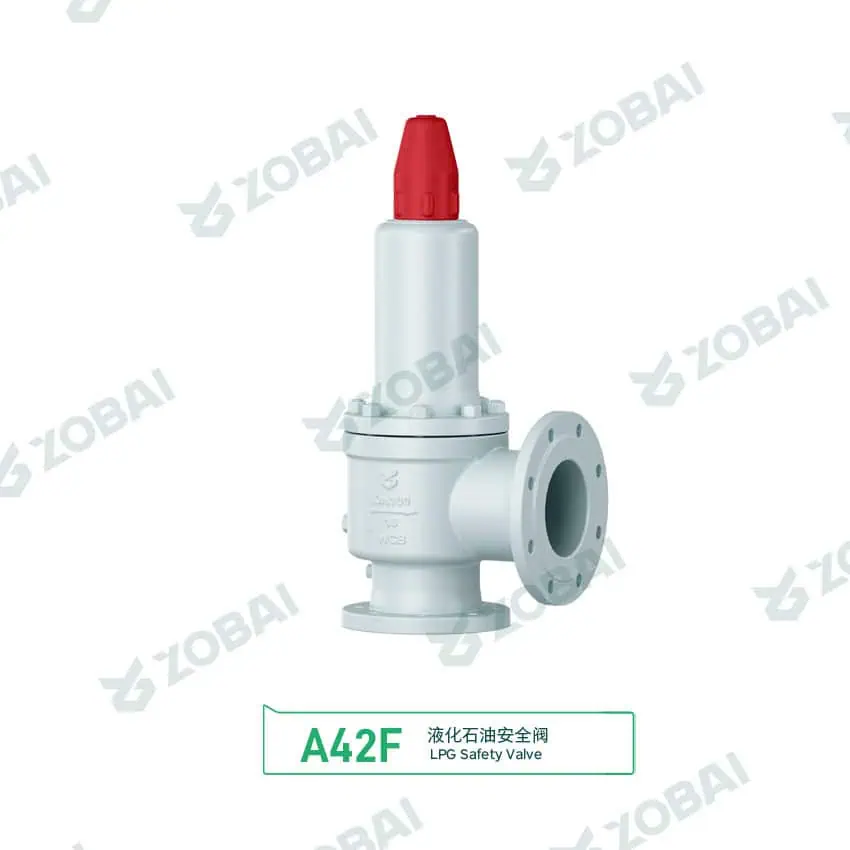
A42F DN100 LPG Safety Valve with Red Cap
LPG Safety Valves for Propane, Butane and Liquefied Petroleum Gas Service
LPG safety valves are pressure relief devices used to protect liquefied petroleum gas equipment from unsafe pressure rise. They are commonly applied on LPG storage tanks, filling stations, vaporizers, transport skids, loading and unloading systems, pump discharge lines, compressor packages and piping sections where trapped LPG may expand as temperature changes.
Why LPG service needs specific relief valve review
LPG is normally stored as a pressurized liquid with vapor space. Pressure can rise because of fire exposure, solar heating, blocked outlet, regulator failure, pump overpressure, compressor discharge restriction, vaporizer malfunction or thermal expansion of trapped liquid. The relief valve must be selected for the credible relief case, not only for the tank connection size.
The valve must also discharge flammable gas or vapor to a safe location. Outlet orientation, rain protection, drainage, ignition source separation, back pressure, discharge header design and inspection access should be reviewed before purchase and installation.
Engineering selection boundary
LPG safety valves may be spring loaded, flanged, threaded, internal, external, full lift, low lift, conventional, balanced or pilot operated depending on the equipment and code requirement. The correct design depends on LPG composition, pressure, temperature, required relieving capacity, tank or line configuration, outlet arrangement and maintenance practice.
A valve that opens correctly can still create a hazard if the outlet discharges toward personnel, air intakes, electrical equipment, ignition sources or enclosed spaces.
LPG safety valve selection should be confirmed by qualified engineering personnel against the applicable pressure equipment code, LPG storage rules, local fire safety requirements and site operating procedure. Do not block, cap, plug or isolate an LPG relief valve unless the design and maintenance procedure specifically allows safe control of the protected equipment.
How an LPG Safety Valve Relieves Pressure
An LPG safety valve senses pressure at the protected tank, vessel, vaporizer, line or equipment nozzle. When pressure reaches the set pressure, the closing force is overcome and the valve opens. The valve may release LPG vapor, liquid, flashing liquid or two-phase flow depending on the relief scenario; the sizing method and certified-capacity basis must match the expected phase behavior. The discharged fluid must be routed safely and the valve must reseat after pressure is reduced.
Pressure Rise
Pressure may rise from fire exposure, heating, overfilling, blocked outlet, pump deadhead, compressor restriction or trapped liquid expansion.
Opening at Set Pressure
The valve begins to open at the specified set pressure. Set pressure must match protected equipment limits and applicable requirements.
Relieving LPG Flow
The valve discharges the required flow if the orifice, certified capacity, inlet path and outlet system are correctly selected.
Safe Venting & Reseating
The outlet must discharge safely, without excessive back pressure. After pressure drops, the valve should reseat tightly.
Design Details That Matter in LPG Relief Service
LPG service combines pressure relief engineering with flammable fluid safety. Capacity sizing, seat tightness, material compatibility and discharge layout must be reviewed together. The relief valve is only one part of the LPG pressure protection system.
Required Relieving Capacity
LPG relief capacity depends on the credible overpressure case. A storage tank fire case, vaporizer failure, pump deadhead or trapped liquid thermal expansion can lead to different flow requirements. The valve should be selected against the governing relief scenario, required relieving capacity and applicable certified-capacity basis, not only against nominal connection size.
For LPG mixtures, composition and temperature affect vapor pressure and relieving behavior. Propane-rich and butane-rich mixtures may not behave the same at the same ambient condition.
Outlet Direction and Flammable Gas Routing
Relief discharge from LPG equipment should be directed to a safe location according to site rules and applicable regulations. The outlet should avoid personnel areas, ignition sources, electrical equipment, building openings, air intakes and enclosed spaces.
If the valve discharges into a header, stack, flare or recovery system, built-up back pressure and simultaneous relief cases must be reviewed.
Seat Tightness and Reseating
Seat tightness is important in LPG service because even small leakage can create odor, product loss and flammable atmosphere concerns. Leakage may be caused by debris, frost, corrosion, improper installation, chatter, damaged seat surfaces or operating pressure too close to set pressure.
Soft seats may improve tightness in suitable service, but they must be checked against LPG composition, pressure, temperature, pressure-drop cooling, fire-case exposure assumptions and site maintenance practice.
Material and Seal Compatibility
Body, trim, spring, gasket and seal materials must be compatible with LPG composition, service temperature, outdoor exposure and any contaminants. In some LPG systems, low ambient temperature, pressure drop cooling and weather exposure should also be considered.
For sour, contaminated or special LPG service, additional material requirements may apply depending on the project specification.
LPG Safety Valve Fit Check
Use this screening tool to identify which LPG relief design issues need closer review. This is not a sizing calculation. Final selection depends on LPG composition, protected equipment, set pressure, relief case, capacity, back pressure, discharge routing and applicable local requirements.
Initial result: confirm capacity and discharge safety
LPG service requires both pressure relief sizing and safe flammable discharge review. Confirm the protected equipment, relief case, set pressure, certified capacity, outlet direction and back pressure before selecting a valve.
Selection Parameters for LPG Safety Valves
LPG Safety Valve vs General Gas Safety Valve
LPG is a liquefied flammable gas. It should not be treated as ordinary compressed air or inert gas service. The valve must be reviewed for both pressure protection and flammable discharge safety.
| Item | LPG Safety Valve | General Gas Safety Valve |
|---|---|---|
| Medium behavior | Liquefied flammable gas with vapor-liquid equilibrium and temperature-dependent pressure. | May be air, nitrogen, steam, vapor or process gas depending on service. |
| Main relief cases | Fire exposure, thermal expansion, overfilling, regulator failure, blocked outlet, pump or compressor overpressure. | Blocked outlet, control failure, thermal expansion, fire case or process upset depending on system. |
| Discharge concern | Flammable vapor release must be directed away from ignition sources and personnel exposure. | Discharge risk depends on toxicity, temperature, noise, pressure and gas type. |
| Seat tightness focus | High importance because leakage may create odor, product loss and flammable atmosphere risk. | Important, but consequence depends on medium and site hazard classification. |
| Material review | Must consider LPG compatibility, outdoor exposure, low-temperature effects and contaminants where applicable. | Depends on gas composition, pressure, temperature and corrosion risk. |
| Best selection logic | Select by LPG composition, protected equipment, relief case, capacity, discharge safety and applicable LPG rules. | Select by medium, pressure, temperature, required capacity, back pressure and code requirement. |
Where LPG Safety Valves Are Used
LPG storage tanks and pressure vessels
LPG tanks require relief protection against pressure rise from heating, fire exposure and abnormal operating events. Selection should consider tank MAWP or design limit, set pressure, fire-case basis, wetted surface or applicable exposure basis, certified capacity and discharge location.
LPG filling stations and bottling plants
Filling manifolds, transfer lines and bottle filling systems may need pressure relief for blocked-in liquid, pump overpressure and operational upset. Outlet routing should avoid filling operators and ignition sources.
Vaporizers, heaters and pressure reducing systems
LPG vaporizers and pressure control systems can create overpressure if heat input, regulator operation or downstream isolation is abnormal. Valve selection should include vaporizer capacity, relieving phase and discharge path.
Pump, compressor and loading systems
Pump discharge, compressor discharge and truck or rail loading systems may require relief valves to protect against blocked discharge, deadheading, pressure surge or thermal expansion in isolated liquid sections.
LPG Safety Valve Selection Table
| LPG Service | Typical Relief Case | Recommended Valve Review | Main Risk | RFQ Data Needed |
|---|---|---|---|---|
| Storage tank | Fire exposure, solar heating, overfilling or blocked outlet | Set pressure, fire case capacity, tank MAWP, discharge direction and weather protection | Insufficient capacity, unsafe flammable discharge or blocked vent outlet | Tank size, LPG composition, design pressure, set pressure, required capacity, installation drawing |
| Filling manifold | Pump overpressure, closed valve or blocked filling line | Liquid relief behavior, set pressure, outlet routing and operator exposure | Liquid release, pressure surge or discharge toward work area | Line size, pump data, LPG phase, set pressure, discharge arrangement |
| Blocked-in liquid line | Thermal expansion of trapped liquid LPG | Thermal relief valve sizing, isolation boundary, discharge destination and leakage control | Rapid pressure rise in isolated piping section | Line volume, liquid condition, temperature range, set pressure, discharge location |
| Vaporizer | Heat input, regulator failure, blocked downstream line or abnormal vapor generation | Relieving phase, capacity, temperature, material and outlet back pressure | Undersized relief, two-phase flow uncertainty or unsafe venting | Vaporizer capacity, LPG composition, operating temperature, set pressure, relief scenario |
| Compressor discharge | Blocked discharge, control failure or pressure surge | Gas capacity, pulsation, vibration, outlet header and seat tightness | Chatter, leakage, noise or excessive back pressure | Gas composition, flow rate, pressure, temperature, discharge pipe layout |
| Common relief header | Multiple relief points connected to a shared outlet system | Superimposed and built-up back pressure, simultaneous relief assumptions and safe discharge | Capacity reduction, unstable operation or flammable gas accumulation | Header layout, pipe length, fittings, design pressure, simultaneous relief basis |
This table is for engineering screening only. Final selection depends on LPG composition, equipment design pressure, set pressure, relieving case, phase behavior, required capacity, back pressure, discharge system and applicable code requirements.
Mistakes That Create Risk in LPG Relief Systems
Using tank connection size as the sizing basis
The relief valve connection may match the tank nozzle, but that does not prove the valve can discharge the required fire case or process upset capacity. Required capacity and certified capacity must be reviewed.
Ignoring where flammable vapor will go
LPG relief discharge should not be aimed at operators, walkways, building openings, air intakes, electrical equipment or likely ignition sources. Outlet orientation and safe vent location are part of valve selection.
Letting rain, debris or corrosion affect the outlet
Outdoor LPG valves may be exposed to rain, dust, insects, corrosion and weather. Outlet protection, drainage, inspection and recalibration should be included in the maintenance plan.
LPG Safety Valve Troubleshooting Table
| Symptom | Possible Cause | Engineering Check | Corrective Action |
|---|---|---|---|
| Valve leaks or smells of LPG | Seat damage, dirt, frost, corrosion, operating pressure too close to set pressure or poor reseating | Check seat condition, pressure history, medium cleanliness, outlet exposure and calibration record | Isolate according to site procedure, inspect, clean, repair, recalibrate or replace the valve |
| Valve chatters during relief | Excessive inlet pressure loss, high back pressure, oversized valve or unstable two-phase behavior | Review inlet path, outlet header, relief case, capacity and actual phase condition | Recalculate sizing, reduce inlet loss, review back pressure or select a suitable valve type |
| Valve opens frequently | Operating pressure close to set pressure, regulator malfunction, overfilling, thermal expansion or process instability | Check operating pressure trend, fill level, regulator setting and thermal exposure | Correct process cause, confirm set pressure and review operating margin |
| Outlet is blocked or restricted | Rain cap damage, debris, ice, insects, corrosion, wrong discharge pipe or poor maintenance | Inspect outlet path, drainage, weather protection and vent termination | Clear obstruction, repair outlet arrangement and improve inspection procedure |
| Capacity appears insufficient | Wrong orifice, incorrect LPG composition, wrong relief case, high back pressure or restrictive inlet | Review sizing basis, certified capacity, back pressure and LPG properties | Reselect valve, correct installation or revise relief system design |
| External corrosion or damaged nameplate | Outdoor exposure, poor coating, missing protection or inadequate inspection | Check body condition, spring chamber, nameplate visibility and maintenance history | Repair or replace valve, restore identification and improve corrosion protection |
Standards and Documents to Confirm
Standards commonly reviewed
LPG safety valve selection may involve pressure vessel rules, pressure relief sizing standards, local LPG installation rules, fire safety requirements and project specifications. The applicable standard should be defined by the protected equipment, country, installation type and end user requirement.
- ASME BPVC Section VIII for pressure vessel applications where applicable.
- API 520 Part I for sizing and selection of pressure relief devices in process systems.
- API 520 Part II / installation guidance for installation considerations, including inlet and outlet effects.
- API 521 for overpressure scenario and relief system review.
- API 526 for flanged steel pressure relief valve dimensions and orifice designation where applicable.
- API 527 where the selected valve design and project specification use API 527; otherwise confirm the applicable leakage criterion.
- ISO 4126-1 for safety valve requirements where applicable.
- NFPA 58, 2024 Edition or the locally adopted LPG code where required by the project jurisdiction.
- ISO 15156-1 / NACE MR0175 where the project falls within its H₂S-containing oil and gas production scope; confirm downstream, refining or other contaminated-LPG material requirements separately.
- National Board / NBIC requirements where repair, recalibration or jurisdictional inspection rules apply.
Documents buyers often request
LPG applications should be documented clearly because the valve protects pressure equipment handling flammable service. The documentation package should match the project specification, inspection plan and local approval requirements.
- Valve datasheet with model, size, set pressure, material and connection standard.
- Required relieving capacity and sizing basis when specified.
- Certified capacity or flow coefficient information where required.
- Set pressure calibration record.
- Seat tightness test report when leakage control is specified.
- Material certificates for body, trim, spring or wetted parts where required.
- Nameplate, tag number and installation orientation information.
- Operation, inspection, maintenance and recalibration instructions.
Related Pages for LPG Pressure Relief Selection
Use these ZOBAI pages to connect LPG safety valve selection with related valve types, applications, standards and engineering checks.
Valve Types
LPG Applications
External Standards for LPG Safety Valve Review
These external references should be used as authority links only. Final project requirements still depend on jurisdiction, protected equipment, owner specification and engineering approval.
Pressure Relief and Safety Valve Standards
LPG, Storage and Material References
- NFPA 58, 2024 Edition — Liquefied Petroleum Gas Code
- NFPA 58 Standard Development
- API Digital Catalog — API 2510 / API 2000 scope check; API 2000 applies to atmospheric and low-pressure tank venting and is not the general relief-sizing basis for pressurized LPG vessels.
- ISO 15156-1:2020 / NACE MR0175 for applicable H₂S-containing oil and gas production environments.
- 49 CFR §195.264 as a scope-limited U.S. hazardous-liquid pipeline-facility reference for aboveground breakout tanks; do not apply it as a general LPG storage rule.
- National Board NB-18 for searchable pressure-relief-device manufacturer, design-certification and certified-device information.
LPG Safety Valve FAQs
These answers clarify LPG overpressure protection, general-gas valve suitability, thermal relief, RFQ data and safe discharge routing.
Need Help Selecting an LPG Safety Valve?
Send the LPG composition, protected equipment information and relief scenario before quotation. For replacement projects, include the existing valve nameplate, installation photos and discharge arrangement. This helps confirm whether the selected valve can meet the set pressure, capacity, material and safe discharge requirements.
Prepare these data before RFQ
TECHNICAL INSIGHTS
Insights for Safer Valve Selection
FAQ
LPG Safety Valve FAQ
What is an LPG safety valve?
An LPG safety valve is a pressure relief valve used to protect liquefied petroleum gas equipment from unsafe pressure rise. It may be installed on storage tanks, vaporizers, filling stations, pump lines, compressor packages, transport skids and isolated liquid piping sections.
What causes pressure rise in LPG systems?
Pressure rise may be caused by fire exposure, solar heating, overfilling, regulator failure, blocked outlet, pump deadheading, compressor discharge restriction, vaporizer malfunction or thermal expansion of trapped liquid LPG. The correct relief case should be defined before selecting the valve.
Can the same safety valve be used for propane and butane?
Sometimes, but it should not be assumed without review. Propane, butane and LPG mixtures have different vapor pressures and relieving behavior. The valve selection should consider LPG composition, operating temperature, set pressure, required capacity and applicable project requirements.
What is an LPG thermal relief valve?
An LPG thermal relief valve is used to protect blocked-in liquid LPG piping or isolated equipment sections from pressure rise caused by liquid thermal expansion. It is commonly used on pump discharge lines, filling manifolds, loading arms and trapped liquid sections.
Why is seat tightness important for LPG safety valves?
Seat tightness is important because LPG leakage can create odor, product loss and flammable vapor accumulation. Leakage may be caused by dirt, frost, corrosion, seat damage, chatter, poor reseating or operating pressure too close to set pressure.
Can LPG safety valves discharge into a common header?
Yes, but the header must be reviewed for superimposed back pressure, built-up back pressure, simultaneous relief cases, outlet resistance and safe disposal. If back pressure is significant or variable, a balanced or pilot operated valve may need engineering review.
What standards apply to LPG safety valves?
Applicable standards depend on the protected equipment, installation location and project specification. Common references may include ASME BPVC Section VIII, API 520, API 521, API 527, ISO 4126, NFPA 58 or local LPG regulations where applicable.
What information is needed to quote an LPG safety valve?
The RFQ should include LPG composition, protected equipment type, set pressure, operating pressure, temperature range, relief case, required capacity, back pressure, inlet and outlet connection, material requirement, discharge arrangement, applicable standard and quantity.
Raymon Yu
“When a safety valve fails to pop on site, it’s rarely because someone can’t read a standard. It’s usually because critical operating parameters (like backpressure or relief temperature) were assumed instead of specified. I reviewed the key technical content on this page to keep it practical, API/ASME spec-aligned, and RFQ-ready. (We prefer assumptions for lunch choices.)”
What I work on daily: reviewing drawings and project specs, supporting engineer-to-engineer questions, resolving capacity calculations, material selection, and backpressure impacts so production and quoting stay consistent. (Yes—set pressure and seat tightness test records get plenty of attention.)