High-Capacity Pressure Relief for Process Systems
Large Orifice Safety Valves Manufacturer
Large orifice safety valves are selected when the required relieving capacity is too high for smaller orifice valves under the specified medium, set pressure, temperature and back pressure conditions. They are used for high-flow steam, gas, vapor and liquid relief cases in pressure vessels, reactors, compressor systems, steam headers, process skids and storage equipment. Selection must confirm required relieving capacity, certified capacity, orifice area, inlet pressure loss, outlet back pressure, reaction force, material compatibility and applicable code requirements.
Service: Steam / Gas / Vapor / Liquid
Capacity Focus: Required Flow / Certified Capacity / Orifice Area
Applications: Vessels / Reactors / Compressors / Steam Headers
Key Checks: Inlet Loss / Back Pressure / Reaction Force / Noise
Valve Types: Spring Loaded / Bellows Balanced / Pilot Operated Options
Docs: Datasheet / Sizing Basis / Test Report / Material Certificate
Selection should be confirmed against the actual relief case, medium, set pressure, relieving temperature, required capacity, certified capacity, back pressure, inlet pressure loss, installation layout and applicable standards.
Safety Valve Categories
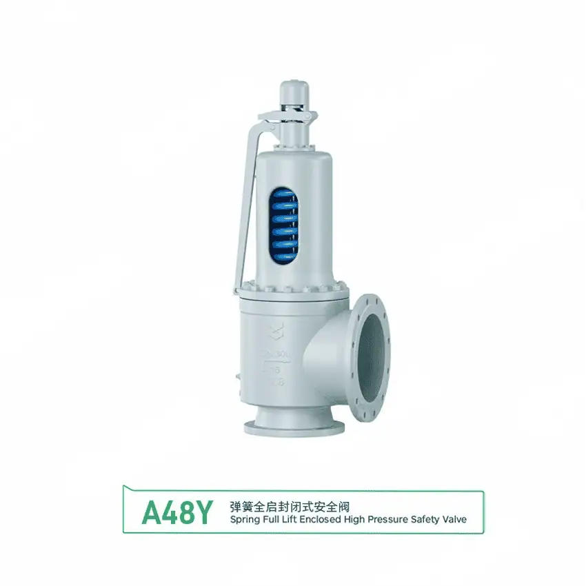
A48Y DN300 Flanged Safety Valve with Window
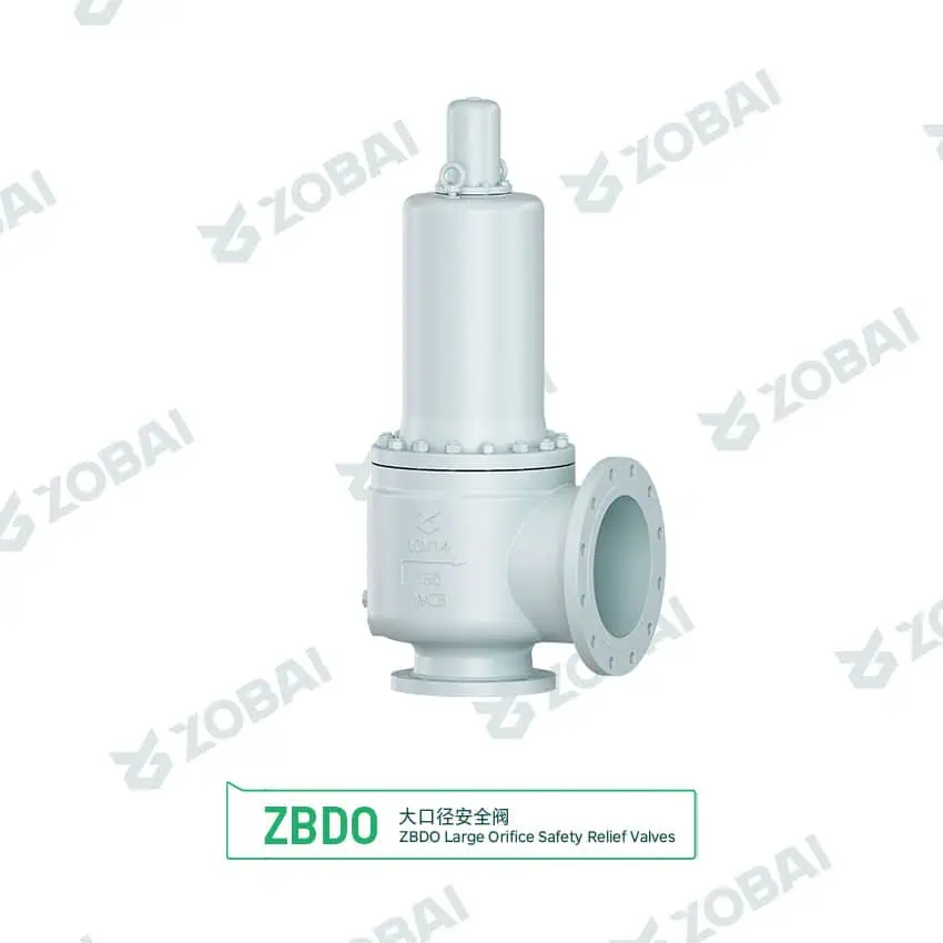
ZBDO 10V14 Enclosed Large Orifice Safety Valve
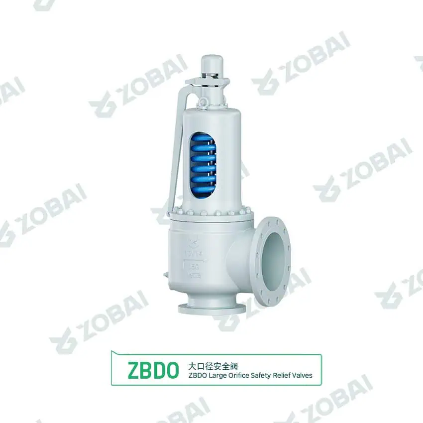
ZBDO 10V14 Open Bonnet Large Orifice Safety Valve
Large Orifice Safety Valves for High-Capacity Pressure Relief
A large orifice safety valve is selected when the protected system requires a higher certified relieving capacity than a smaller orifice valve can provide under the same pressure, temperature and medium conditions. The key engineering question is not whether the valve body looks large, but whether the effective orifice area and certified capacity can safely cover the credible overpressure case.
Large orifice means capacity-driven selection
Large orifice safety valves are commonly used on pressure vessels, reactors, boilers, steam headers, compressor discharge systems, storage equipment, process skids and high-flow gas or vapor services. They may be required when the relieving case involves fire exposure, blocked outlet, control valve failure, thermal expansion, compressor surge, vapor generation or large inflow imbalance.
The valve should be selected from the governing relief scenario and required relieving capacity backward. Set pressure, overpressure, medium properties, relieving temperature, back pressure, inlet pressure loss, discharge piping and certified capacity must be reviewed before choosing the orifice and connection size.
Engineering selection boundary
A large orifice valve is not automatically safer than a properly sized smaller valve. Oversizing can cause chatter, unstable lift, poor reseating, excessive discharge force and unnecessary cost. The correct orifice depends on medium, set pressure, allowable overpressure, required capacity, back pressure and applicable standard.
A large inlet connection does not guarantee sufficient capacity. Orifice area, valve type, certified capacity and the actual relieving conditions must be verified.
How a Large Orifice Safety Valve Handles High Flow
The basic opening principle is the same as other safety valves. When inlet pressure reaches the set pressure, the disc begins to lift. During overpressure, the valve must reach enough lift and flow area to discharge the required mass or volumetric flow. In large orifice service, the discharge event can create high velocity, noise, vibration, reaction force and built-up back pressure, so the piping system becomes part of the pressure relief design.
Relief Case Defined
The credible overpressure scenario is identified, such as fire case, blocked outlet, regulator failure or vapor generation.
Capacity Calculated
The required relieving capacity is calculated using medium properties, pressure, temperature and applicable sizing method.
Orifice Selected
The calculated required area is compared with available effective areas and certified capacities under the applicable code and manufacturer basis; arbitrary oversizing should be avoided.
Piping Verified
Inlet pressure loss, outlet back pressure, support load, reaction force and safe discharge route are reviewed.
Design Details That Matter for Large Orifice Valves
Large capacity pressure relief is not only a valve selection task. Once the orifice becomes large, inlet piping losses, outlet header pressure, discharge loads, vibration, noise and maintenance access become more important. A valve with enough nameplate capacity may still operate poorly if the installation layout is wrong.
Orifice Area and Certified Capacity
The effective orifice area is part of the available flow path, but capacity must be verified using the applicable sizing method, manufacturer-certified data and the actual relieving conditions. API 526 letter designations may be used only where the selected flanged steel pressure-relief-valve series conforms to that standard. Other manufacturers and valve types may use different effective areas, so a letter designation alone does not prove interchangeability.
For replacement projects, the old valve model, orifice designation, set pressure and certified capacity should be checked before assuming interchangeability.
Inlet Pressure Loss and Chatter Risk
Large orifice valves can draw high flow quickly when they open. If the inlet pipe, vessel nozzle, reducer or block valve creates excessive pressure loss, the pressure at the valve inlet can drop during discharge. This may cause repeated opening and closing, known as chatter.
The inlet line should be short, direct and properly sized according to the applicable installation practice and project requirements.
Outlet Back Pressure and Discharge Loads
High relieving flow can generate high outlet velocity, noise and reaction force. Long discharge piping, silencers, flare headers, recovery lines and common relief headers may create built-up back pressure that affects capacity and valve stability.
Outlet piping should be reviewed for back pressure, drainage, support, thermal expansion and safe discharge location.
Stable Lift, Blowdown and Reseating
Oversized valves may not reach stable lift if the actual relief flow is much lower than the valve capacity. This can cause flutter, chatter, seat damage and leakage after operation.
Blowdown, operating pressure margin, medium phase, valve type and discharge system should be reviewed together when large orifice valves are selected.
Large Orifice Safety Valve Fit Check
Use this screening tool to understand whether a large orifice valve may be required. This is not a sizing calculation. Final orifice selection must be based on required relieving capacity, certified capacity, medium properties, pressure, temperature, back pressure and applicable code requirements.
Initial result: capacity review required
A large orifice valve may be considered when the required relieving capacity exceeds the available capacity of smaller orifice options. Confirm the relief case, certified capacity, inlet pressure loss and outlet back pressure before selecting a model.
Selection Parameters for Large Orifice Safety Valves
Large Orifice vs Standard Orifice Safety Valve
The correct valve is the one that matches the required relieving capacity and operates stably. A larger orifice should be selected when capacity requires it, not as a default “safer” option.
| Item | Large Orifice Safety Valve | Standard Orifice Safety Valve |
|---|---|---|
| Main purpose | Provides higher certified relieving capacity for high-flow relief cases. | Provides pressure relief where required capacity can be covered by smaller or moderate orifice sizes. |
| Typical application | Large vessels, reactors, steam headers, compressor systems, fire case relief and high vapor generation service. | General vessels, small process packages, utility systems, thermal relief and moderate flow applications. |
| Main selection basis | Required relieving capacity, certified capacity, orifice area, inlet loss and outlet back pressure. | Set pressure, required capacity, medium, material and installation layout. |
| Installation sensitivity | Higher sensitivity to inlet loss, discharge force, outlet resistance, noise and support design. | Still requires correct installation, but discharge loads may be lower depending on service. |
| Oversizing risk | Higher risk of chatter, flutter, poor reseating and mechanical stress if capacity is far above demand. | Oversizing remains possible, but the mechanical impact may be less severe. |
| Best selection logic | Use when smaller orifices cannot meet the required certified capacity. | Use when capacity demand can be met without creating unnecessary instability or cost. |
Where Large Orifice Safety Valves Are Used
Pressure vessels and reactors
Large vessels and reactors may require high relieving capacity during fire exposure, vapor generation, runaway reaction or blocked outlet conditions. The valve should be sized against the credible case and checked for discharge piping loads.
Steam headers and boiler-related systems
Steam service can require large mass flow relief. Selection should include set pressure, steam capacity, blowdown, reaction force, outlet discharge safety and applicable boiler or pressure equipment requirements.
Compressor discharge and gas systems
Compressor systems can create high gas flow during blocked discharge or control failure. The valve and discharge system should be reviewed for noise, vibration, back pressure and stable lift.
Process skids and high-flow packages
Packaged equipment may have limited piping space, but large orifice relief still requires short inlet piping, safe discharge routing, support design and access for testing and maintenance.
Large Orifice Safety Valve Selection Table
| Service Condition | Why Large Orifice May Be Needed | Recommended Engineering Check | Main Failure Risk | RFQ Data Needed |
|---|---|---|---|---|
| Fire case relief | High vapor generation may require large certified capacity. | Fire case basis, relieving temperature, medium phase, orifice and outlet system. | Undersized capacity, high reaction force or excessive back pressure. | Protected volume, medium, set pressure, fire case data, discharge route. |
| Large steam system | Steam mass flow demand may exceed smaller valve capacity. | Steam condition, set pressure, blowdown, discharge reaction and noise. | Chatter, poor reseating, unsafe discharge or seat damage. | Steam pressure, temperature, required capacity, code basis, connection standard. |
| Compressor discharge | Blocked outlet or control failure may create high gas flow. | Gas properties, relieving pressure, discharge header, vibration and pulsation. | High noise, unstable lift or excessive built-up back pressure. | Gas composition, molecular weight, temperature, capacity, outlet layout. |
| Reactor or vapor generation | Reaction, boiling or heat input may require high vapor relief. | Relief scenario, phase behavior, material compatibility and discharge treatment. | Wrong phase assumption, insufficient capacity or blocked discharge path. | Relief case, fluid properties, set pressure, temperature, required capacity. |
| Flare or common header discharge | Large flow may increase built-up back pressure in the header. | Superimposed back pressure, simultaneous relief, header hydraulics and valve type. | Capacity reduction, chatter or failure to reseat. | Header pressure, pipe length, fittings, simultaneous relief assumptions. |
| Replacement of existing PSV | Old valve may have a specific orifice and certified capacity requirement. | Nameplate, model, orifice designation, set pressure, capacity and flange rating. | Wrong replacement by connection size only. | Photos, nameplate, datasheet, service condition, existing installation drawing. |
This table is for engineering screening only. Final selection depends on medium, set pressure, relieving temperature, required capacity, certified capacity, back pressure, inlet pressure loss, valve type, installation layout and applicable project requirements.
Mistakes That Cause Large Orifice Valve Problems
Selecting the largest orifice as a safety margin
A valve that is too large for the actual flow may not lift stably. It can flutter, chatter, damage the seat and leak after operation. Capacity margin should be controlled by calculation and certified data, not by choosing the biggest available orifice.
Ignoring inlet pressure loss
Large orifice valves pull high flow through the inlet quickly. If the inlet line is too long, restricted or full of fittings, the valve may see unstable pressure and chatter during relief.
Underestimating outlet force and back pressure
High capacity discharge can create strong reaction force, high noise and built-up back pressure. The outlet pipe, supports, header and safe discharge location must be reviewed as part of the valve selection.
Large Orifice Safety Valve Troubleshooting Table
| Symptom | Possible Cause | Engineering Check | Corrective Action |
|---|---|---|---|
| Valve chatters during relief | Oversized orifice, excessive inlet pressure loss or high back pressure | Check relief flow, inlet piping, outlet resistance and actual operating case | Recalculate sizing, reduce inlet loss, review discharge system or select suitable valve type |
| Valve leaks after opening | Seat damage from chatter, debris, vibration or poor reseating | Inspect seat, disc, guide and operating pressure margin | Clean, repair, lap, recalibrate and correct the root cause of instability |
| Discharge noise is excessive | High velocity gas or steam discharge, poor outlet layout or no silencing plan | Review outlet velocity, discharge location, acoustic requirement and silencer back pressure | Review discharge design, add suitable noise control and recalculate back pressure |
| Outlet piping moves during relief | Reaction force, inadequate support or thermal expansion stress | Check discharge force, pipe support, anchor location and flexibility | Improve supports, revise outlet routing and review nozzle loading |
| Valve does not reach required capacity | Wrong orifice, incorrect sizing basis, high back pressure or inlet restriction | Review certified capacity, required capacity and system hydraulics | Select correct orifice, reduce restrictions or revise relief system design |
| Valve opens too frequently | Operating pressure too close to set pressure, process pulsation or incorrect set pressure | Check operating pressure history, calibration record and process stability | Increase operating margin where possible, recalibrate or review control system behavior |
Standards and Documents to Confirm
Standards commonly reviewed
Large orifice safety valves are usually selected under the same pressure relief engineering framework as other safety valves, but installation loads and discharge system effects require closer attention. Applicable standards depend on the protected equipment, market, medium and project specification.
- ASME BPVC Section VIII for pressure vessel protection where applicable.
- ASME BPVC Section I for boiler-related service where applicable.
- API 520 Part I for sizing and selection of pressure relief devices.
- API 520 Part II / installation guidance for installation considerations in process systems.
- API 521 for overpressure scenarios and relief system design review.
- API 526 for flanged steel pressure relief valve dimensions and orifice designation where applicable.
- API 527 where the selected valve design and project specification use API 527; otherwise confirm the applicable leakage criterion.
- ISO 4126-1 for safety valve requirements where applicable.
- API RP 576 inspection reference for pressure-relieving-device inspection, testing, maintenance and repair practices.
- NBIC / National Board NB-18 requirements where repair, recalibration or jurisdictional rules apply.
Documents buyers often request
For large orifice valves, documentation should show not only the valve model but also the capacity basis. The discharge system and installation drawing are often needed because high relieving flow can affect pipe support, back pressure and safe venting.
- Valve datasheet with model, size, set pressure, material and connection standard.
- Orifice designation and certified capacity data where required.
- Required relieving capacity and sizing basis.
- Set pressure calibration record.
- Seat tightness test report when leakage control is specified.
- Material certificates for body, trim, bolting or wetted parts where required.
- Installation drawing, discharge orientation and outlet piping information.
- Inspection, testing and maintenance documentation.
Related Pages for Large Orifice Safety Valve Selection
Use these internal resources to connect large orifice selection with valve type, certified capacity, back pressure, installation layout, flange dimensions and high-flow application review.
Product and valve type pages
- Safety Valves for the complete industrial safety valve category.
- Full Lift Safety Valves for rapid-opening, high-discharge designs where the service and certified data support that configuration.
- Large Capacity Safety Valves for high-flow PSV application review.
- Flanged Safety Valves for bolted high-capacity installations.
- Spring Loaded Safety Valves for conventional direct-acting designs.
- Pilot Operated Safety Valves for clean high-capacity and high operating margin service.
- Bellows Balanced Safety Valves for back pressure and corrosive outlet conditions.
- Back Pressure Balanced Safety Valves for discharge header and variable back pressure cases.
Applications and engineering guides
- Pressure Vessel Safety Valves for MAWP, fire case and vessel protection review.
- Compressor Safety Valves for blocked discharge and high gas flow cases.
- Skid System Safety Valves for compact high-flow package layouts.
- Petrochemical Safety Valves for refinery, gas and process plant relief systems.
- Safety Valve Selection Guide for medium, pressure, capacity and material screening.
- Safety Valve Sizing Guide for required capacity, certified capacity and orifice selection.
- Back Pressure and Bellows for superimposed and built-up back pressure review.
- Safety Valve Installation Guide for inlet loss, outlet piping and support checks.
External Standards References for High-Capacity Safety Valve Projects
These authoritative sources are useful when buyers need to verify sizing, relief scenarios, orifice language, certified capacity, installation requirements and pressure equipment code context.
API and ISO references
- API 520 Part I, 10th Edition for pressure-relieving-device sizing and selection in its applicable process-industry scope.
- API 521 for pressure-relieving and depressuring system design guidance.
- API Standard 527 for seat-tightness requirements where specified for the selected pressure relief valve.
- ISO 4126-1 for safety valve general requirements.
ASME and National Board references
- ASME BPVC Section VIII Division 1 for pressure vessel rules.
- ASME BPVC Section XIII for overpressure-protection rules covering pressure relief devices, testing, marking, capacity certification and installation.
- National Board NB-18 for pressure relief device certification listings.
- National Board Pressure Relief Laboratory for pressure-relief-device flow testing and certification resources.
Large Orifice Safety Valve FAQs
These answers clarify when a larger effective area is required, why inlet size is insufficient, how oversizing causes instability and what data is needed before quotation.
Need Help Selecting a Large Orifice Safety Valve?
Send the process data, required relieving capacity and installation layout before quotation. For replacement projects, include the existing valve nameplate, datasheet, orifice designation and discharge piping photos. This helps confirm whether a large orifice valve is required and whether the piping system can support stable operation.
Prepare these data before RFQ
TECHNICAL INSIGHTS
Insights for Safer Valve Selection
FAQ
Large Orifice Safety Valve FAQ
What is a large orifice safety valve?
A large orifice safety valve is a pressure relief valve selected with a larger effective flow area to provide higher relieving capacity. It is used when the required relieving capacity cannot be met by a smaller orifice valve under the specified medium, set pressure, temperature and back pressure conditions.
Is a large orifice valve always safer than a smaller valve?
No. A valve should not be oversized as a safety margin. If the orifice is much larger than the actual relief demand, the valve may chatter, flutter, fail to reach stable lift, damage the seat or leak after operation. The correct valve is the one that meets required capacity and operates stably.
What data is needed to size a large orifice safety valve?
Key data include medium, phase, molecular weight or density where applicable, set pressure, operating pressure, relieving temperature, required relieving capacity, overpressure, back pressure, inlet pressure loss, connection standard, material requirement and applicable code.
What is the difference between orifice area and connection size?
Connection size refers to the inlet or outlet connection, such as flange or thread size. Orifice area is the effective internal flow area used for capacity. Two valves with similar connection sizes may have different orifice areas and different certified relieving capacities.
Why do large orifice safety valves chatter?
Common causes include oversized valve capacity, excessive inlet pressure loss, high built-up back pressure, unstable process flow, poor outlet piping layout or operating pressure too close to set pressure. Chatter should be investigated because it can damage the seat and reduce reliability.
Can a large orifice safety valve discharge into a common header?
Yes, but the common header must be reviewed for superimposed back pressure, built-up back pressure, simultaneous relief cases, outlet resistance and safe discharge. If back pressure is significant or variable, a balanced or pilot operated valve may need to be considered depending on the service.
Which standards are commonly used for large orifice safety valves?
Common references may include ASME BPVC Section VIII, ASME BPVC Section I, API 520, API 521, API 526, API 527, ISO 4126 and project-specific pressure equipment rules. The applicable standard depends on the protected equipment, medium, market and project specification.
What should be checked when replacing an existing large orifice safety valve?
Check the existing valve nameplate, model, orifice designation, set pressure, certified capacity, material, connection rating, discharge direction and installation layout. Replacement by connection size alone may result in a valve with insufficient capacity or unstable performance.

Raymon Yu
“When a safety valve fails to pop on site, it’s rarely because someone can’t read a standard. It’s usually because critical operating parameters (like backpressure or relief temperature) were assumed instead of specified. I reviewed the key technical content on this page to keep it practical, API/ASME spec-aligned, and RFQ-ready. (We prefer assumptions for lunch choices.)”
What I work on daily: reviewing drawings and project specs, supporting engineer-to-engineer questions, resolving capacity calculations, material selection, and backpressure impacts so production and quoting stay consistent. (Yes—set pressure and seat tightness test records get plenty of attention.)