Duty Standby Pressure Relief Configuration
Dual Safety Valves for Maintainable Pressure Relief Systems
Dual safety valves are used when a protected system needs a maintainable relief path. In a typical duty and standby arrangement, one safety valve remains in service while the other can be inspected, repaired, cleaned, or recalibrated. The key engineering point is not the number of valves, but whether the arrangement maintains required relieving capacity without creating an unsafe isolation condition.
Duty / Standby PSV Assembly
Changeover Valve Configuration
Back Pressure Review
Certified Capacity Check
Maintenance Access Planning
Reviewed for sizing logic, changeover arrangement, inlet loss, outlet piping, back pressure, maintenance access, and RFQ data requirements before valve selection.
Safety Valve Categories
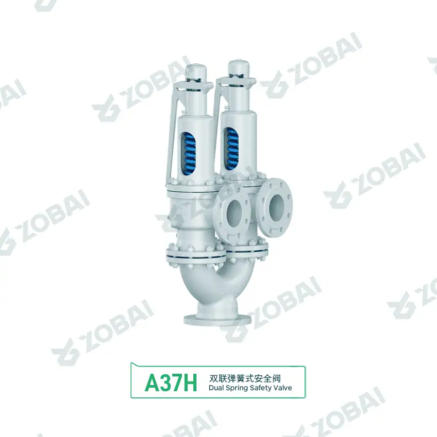
A37H DN125 Parallel Dual Safety Valve
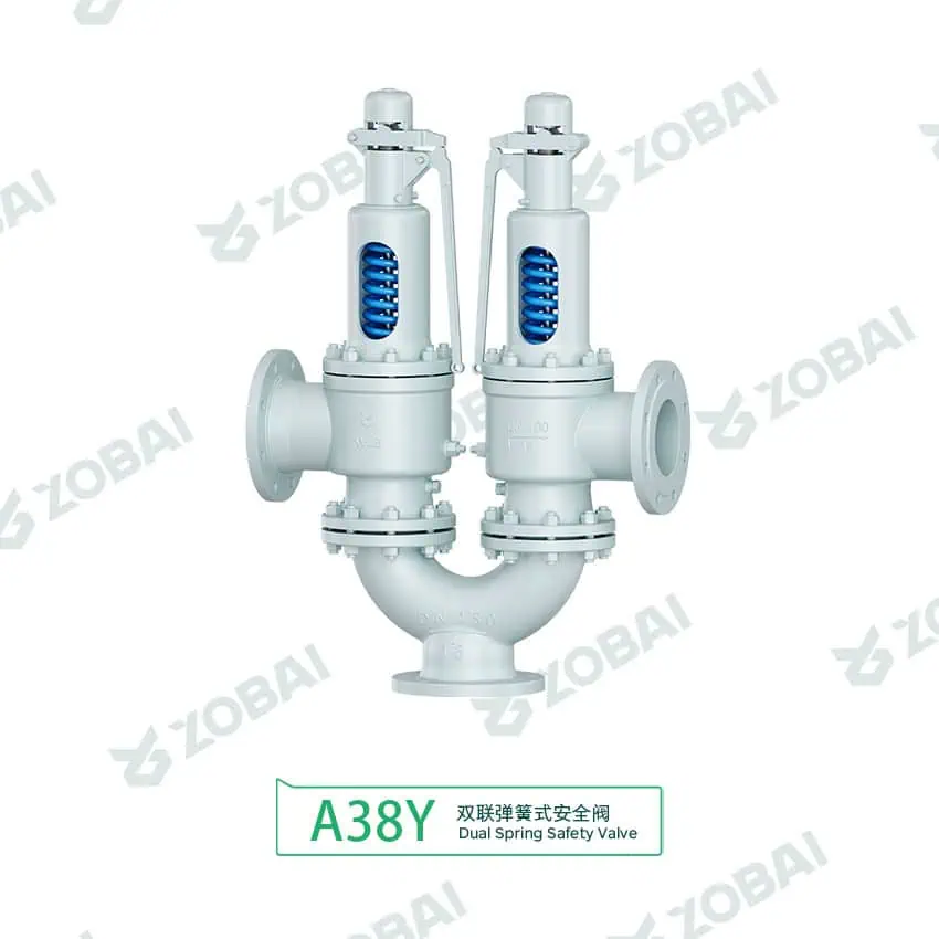
A38Y DN150 Twin Dual Safety Valve
Dual Safety Valves for Maintainable Pressure Relief Protection
Dual safety valves are used when a pressure system needs one available relief path while another valve is inspected, repaired, cleaned or recalibrated. In most duty standby arrangements, the engineering purpose is not to double the number of valves, but to make sure the protected equipment is never left without a qualified pressure relief path.
Why dual safety valves are selected
A dual safety valve arrangement is commonly used on pressure vessels, process skids, compressor packages, steam systems, gas headers and equipment where shutdown is difficult. One valve can remain in service while the standby valve is removed for inspection or recalibration.
The main engineering check is whether the active valve and changeover path can provide the required relieving capacity under the actual relieving case. The arrangement must also prevent both relief paths from being isolated at the same time.
Engineering selection boundary
Dual safety valves are suitable when online maintenance, standby protection or a controlled switching arrangement is required. They should not be used as a shortcut to avoid proper sizing, discharge piping review or isolation procedure control.
A dual PSV system must be reviewed as one complete pressure relief path, including the active valve, changeover valve, inlet spool, outlet piping, back pressure and operating procedure.
How a Dual Safety Valve Arrangement Works
In a typical duty standby system, one safety valve is connected to the protected equipment while the second valve is isolated or kept ready for service. A changeover valve or switching manifold is used to transfer the active relief path. The design should make sure at least one qualified safety valve remains connected during normal operation and switching.
Normal Protection
One safety valve is active and connected to the pressure source. It must be sized for the assigned relieving case.
Standby Availability
The standby valve remains available for switching or maintenance depending on the project isolation philosophy.
Controlled Changeover
The changeover device transfers the relief path without leaving the protected equipment without pressure relief protection.
Maintenance Window
The isolated valve can be inspected, repaired or recalibrated while the active valve continues to protect the equipment.
Key Design Points in a Dual Safety Valve System
A dual safety valve system should not be selected only by inlet and outlet size. The changeover body, flow direction, valve certification, back pressure, pipe stress, isolation position and maintenance procedure all affect whether the system can actually protect the equipment.
Required Relieving Capacity and Certified Capacity
The active valve must be checked against the credible relieving case. Required capacity may come from blocked outlet, fire exposure, thermal expansion, control valve failure, utility failure, compressor operation or other project-specific scenarios.
Orifice area and nominal connection size are not enough. The selected valve must have suitable certified capacity for the medium, set pressure, relieving temperature and applicable code basis.
Changeover Valve and Isolation Control
The changeover device should not allow both safety valves to be isolated from the protected equipment during normal operation. Depending on site practice, lock-open, car-seal-open, mechanical interlock, position indication or a written switching procedure may be required.
The bore, pressure rating, flow path and end connection of the changeover valve should be checked with the safety valve inlet pressure loss requirement.
Inlet Loss, Outlet Piping and Back Pressure
Dual valve arrangements often add tees, reducers, elbows, manifolds and switching devices. These components may increase inlet pressure loss and outlet back pressure. Excessive inlet loss can cause chatter, unstable opening and seat damage.
Superimposed back pressure and built-up back pressure must be reviewed. Conventional spring loaded, bellows balanced and pilot operated valves do not respond to back pressure in the same way.
Inspection, Recalibration and Standby Readiness
The standby valve should not be treated as an unused spare. Seat tightness, spring condition, nozzle cleanliness, bellows integrity, pilot line cleanliness, gag removal, nameplate data and test records should be included in the maintenance plan.
Recalibration interval depends on medium severity, valve history, leakage experience, local regulation, plant inspection practice and project requirement.
Dual Safety Valve Fit Check
Use this quick fit check for early screening. It does not replace sizing calculation, certified capacity confirmation or project code review.
Start with one active valve sized for the required relieving case. Then verify changeover bore, inlet pressure loss, outlet back pressure, isolation control and valve certification documents.
Parameters That Decide Whether Dual Safety Valves Can Protect the System
Dual Safety Valves vs Single Valve vs Parallel Relief Valves
The correct arrangement depends on whether the project needs maintainability, capacity sharing, back pressure control or simple overpressure protection.
| Arrangement | Typical Purpose | Engineering Check | Main Risk |
|---|---|---|---|
| Single Safety Valve | Basic overpressure protection where shutdown for maintenance is acceptable. | Set pressure, capacity, inlet loss, outlet piping and material compatibility. | No installed standby device during valve removal. |
| Dual Duty Standby Safety Valves | One valve in service while the second valve is available for maintenance or standby use. | Active valve capacity, changeover bore, isolation control and discharge piping. | Incorrect switching or accidental isolation of both relief paths. |
| Parallel Relief Valves | Two or more valves share the required relieving capacity. | Combined certified capacity, set pressure sequence and discharge header back pressure. | Assuming both valves open and flow as intended without dynamic review. |
| Dual Bellows Balanced Valves | Duty standby arrangement where variable back pressure must be considered. | Bellows material, venting, back pressure limits and maintenance inspection. | Bellows failure or blocked vent may change valve behavior. |
| Dual Pilot Operated Valves | Clean service requiring high seat tightness, high set pressure or suitable back pressure performance. | Pilot line cleanliness, sensing location, pilot exhaust and soft goods compatibility. | Contamination or plugging in pilot components. |
Where Dual Safety Valves Are Commonly Used
Continuous process equipment
Reactors, separators, heat exchangers and process vessels may use dual safety valves when relief valve maintenance must be performed without depressurizing the entire system.
Compressor and gas systems
Gas packages, receiver vessels and discharge systems may require standby relief protection because of pressure cycling, operating continuity and maintenance access requirements.
Steam and utility systems
Steam headers, utility skids and auxiliary systems may use dual safety valves where periodic inspection is required and discharge piping reaction force must be controlled.
Chemical and corrosive service
Corrosive, dirty, crystallizing or fouling media may require a maintainable arrangement because nozzle deposits, seat damage and trim corrosion can shorten inspection intervals.
Dual Safety Valve Selection Table
| Project Condition | Likely Arrangement | Valve Type to Review | Key Engineering Check | Main Risk |
|---|---|---|---|---|
| Online maintenance is required and one valve can handle full capacity | Duty standby with changeover valve | Spring loaded, bellows balanced or pilot operated | Certified capacity, changeover bore, inlet loss and isolation control | Both relief paths isolated by operation error |
| Required capacity exceeds one available valve size | Parallel relief valves | Multiple spring loaded or pilot operated valves | Combined capacity, set pressure sequence and discharge header | Incorrect assumption of capacity sharing |
| Variable or significant back pressure exists | Dual assembly with back pressure review | Bellows balanced or pilot operated design | Built-up and superimposed back pressure | Chatter, capacity reduction or poor reseating |
| Dirty, sticky or crystallizing medium | Maintainable dual assembly | Valve type depends on medium behavior | Nozzle deposits, guide sticking and cleaning access | Seat leakage or failure to open fully |
| Sour or corrosive service | Dual assembly with controlled materials | Material selected by project specification | NACE requirement if applicable, trim material and gasket compatibility | Corrosion, spring damage or bellows failure |
This table is for engineering screening only. Final selection depends on medium, pressure, temperature, back pressure, required relieving capacity, valve type, discharge system and project requirements.
Common Engineering Mistakes to Avoid
Both relief paths can be closed
A dual safety valve arrangement can become unsafe if the changeover or isolation design allows both valves to be isolated from the protected equipment. The switching method should be reviewed with lock, car-seal, interlock or procedure control.
Two installed valves are assumed to mean double capacity
In duty standby service, only one valve may be active at a time. If the project requires both valves to relieve together, the system should be designed as a parallel relief valve arrangement with combined certified capacity.
Changeover pressure loss is ignored
Changeover valves, elbows, reducers and inlet spools can increase inlet pressure loss. Excessive pressure loss may cause chatter, unstable lifting, reduced capacity or repeated seat damage.
Dual Safety Valve Troubleshooting Table
| Symptom | Possible Cause | Engineering Check | Corrective Action |
|---|---|---|---|
| Valve chatters during relief | Excessive inlet loss, high back pressure, oversized valve or unstable flow | Check changeover bore, inlet spool, outlet header and relieving case | Review piping, reduce losses or select a more suitable valve arrangement |
| Seat leakage after switching | Debris on seat, thermal distortion, damaged disc or repeated simmering | Inspect nozzle, disc, seat surface and operating pressure margin | Clean, repair, recalibrate and retest seat tightness |
| Standby valve fails recalibration | Spring relaxation, corrosion, deposits or poor storage condition | Check nameplate, spring chamber, test record and material condition | Repair, replace affected parts and recalibrate according to procedure |
| Back pressure affects opening or reseating | Discharge header interaction or wrong valve type | Calculate built-up and superimposed back pressure | Review conventional, bellows balanced or pilot operated design suitability |
| Operator cannot confirm active relief path | Poor position indication, missing tag or unclear procedure | Review valve position indication, tagging and site switching procedure | Add clear identification, lock control, car seal or interlock where required |
Standards and Documentation to Confirm Before Purchase
Standards to review
The applicable standards depend on protected equipment, jurisdiction, industry, medium and project specification. Dual safety valve assemblies are usually reviewed together with pressure relief sizing, installation, inspection and material documents.
- ASME BPVC guidance for pressure vessel and boiler-related safety valve applications where applicable.
- API 520 safety valve sizing for sizing, selection and installation communication.
- API 521 pressure relief systems for relief scenario and depressuring review.
- API 526 flanged safety valves where flanged dimensions and orifice designation are relevant.
- API 527 seat tightness testing when leakage control is specified.
- API RP 576 for pressure-relieving device inspection and maintenance references.
- ISO 4126 safety valve standards where ISO-based pressure relief devices are required.
- Safety valve installation guide for inlet pressure loss, outlet routing and isolation-control checks.
Documents buyers often request
Documentation should be confirmed before manufacturing, especially for critical service, code-controlled equipment or replacement projects.
- Valve datasheet and model specification.
- Sizing calculation or capacity confirmation.
- Certified capacity document where applicable.
- General arrangement drawing for the dual valve assembly.
- Set pressure calibration record.
- Seat tightness test report when leakage control is required.
- Material certificate and traceability documents where specified.
- Nameplate, tagging and installation orientation information.
Related ZOBAI Safety Valve Resources
Use these internal resources to continue the engineering path from dual safety valve concept to valve type, sizing, installation and application review.
Special configurations
Valve type comparison
Application pages
Engineering guides
Authority Links for Dual PSV Engineering Review
These external references support standards-based review of sizing, installation, inspection and pressure equipment code requirements. External standards pages open in a new tab.
API and ISO references
- API 520 Part I for sizing and selection of pressure-relieving devices.
- API 520 Part II for installation reference.
- API 521 for pressure-relieving and depressuring systems.
- API RP 576 for inspection and maintenance topics.
- ISO 4126-1 for general safety valve requirements.
ASME and National Board references
- ASME Boiler and Pressure Vessel Code for pressure equipment code context.
- ASME BPVC Certification for code certification context.
- National Board certified individual reference for ASME mark oversight context.
- 46 CFR pressure-relief device rules for marine pressure vessel regulatory context.
Need Help Reviewing a Dual Safety Valve Assembly?
Send us your operating conditions and maintenance philosophy. Our engineering team can review whether your case needs a duty standby arrangement, parallel relief valves, a changeover valve, bellows balanced valves or pilot operated valves.
Prepare these data before RFQ
TECHNICAL INSIGHTS
Insights for Safer Valve Selection
FAQ
Dual Safety Valves FAQ
What are dual safety valves?
Dual safety valves are two pressure relief devices installed on one protected system, usually in a duty and standby arrangement. One valve remains connected to the protected equipment while the other can be inspected, cleaned, repaired, or recalibrated. The arrangement may use a changeover valve, switching manifold, or controlled isolation system.
Are dual safety valves the same as two valves in parallel?
Not always. In a duty and standby arrangement, one valve is normally active and the other is available as standby. In a parallel relief arrangement, two or more valves may share the required relieving capacity. These two cases require different sizing logic, set pressure review, discharge piping review and documentation.
Why use dual safety valves instead of one safety valve?
Dual safety valves are used when maintenance access is needed without leaving the protected equipment without relief protection. They are common in continuous process systems, pressure vessels, utility skids, compressor systems and equipment where shutdown is difficult or expensive.
Can one valve in a dual safety valve assembly be removed during operation?
It may be possible if the arrangement is specifically designed for duty and standby service and the active valve remains connected to the protected equipment. The changeover valve, isolation procedure, lock or car-seal requirement, and site safety practice must be reviewed before removing any valve.
How should dual safety valves be sized?
Sizing depends on the credible relieving scenario, set pressure, allowable accumulation, required relieving capacity, fluid phase, relieving temperature, back pressure, inlet pressure loss and certified capacity. If one valve is expected to protect the system alone, that active valve must be checked against the required relieving case.
What is the main risk in a dual safety valve system?
The main risk is accidental isolation or restriction of the relief path. This can happen through incorrect changeover position, closed isolation valve, undersized changeover bore, excessive inlet pressure loss, blocked outlet piping or unclear maintenance procedure.
Can dual safety valves be used with back pressure?
Yes, but back pressure must be reviewed carefully. Conventional spring loaded valves, bellows balanced valves and pilot operated valves respond differently to superimposed and built-up back pressure. The discharge system, outlet piping and valve type should be checked before selection.
What information is required for a dual safety valve RFQ?
An RFQ should include protected equipment type, design code, set pressure, operating pressure, medium, phase, relieving temperature, required relieving capacity, relieving scenario, back pressure, connection standard, material requirement, installation layout, changeover requirement and maintenance philosophy.

Raymon Yu
“When a safety valve fails to pop on site, it’s rarely because someone can’t read a standard. It’s usually because critical operating parameters (like backpressure or relief temperature) were assumed instead of specified. I reviewed the key technical content on this page to keep it practical, API/ASME spec-aligned, and RFQ-ready. (We prefer assumptions for lunch choices.)”
What I work on daily: reviewing drawings and project specs, supporting engineer-to-engineer questions, resolving capacity calculations, material selection, and backpressure impacts so production and quoting stay consistent. (Yes—set pressure and seat tightness test records get plenty of attention.)