Share your medium, set pressure, temperature, size, standard, or datasheet, and our team will review your requirement and respond with the appropriate next step.
Safety Valve Maintenance and Inspection Guide for Plant Engineers
What Should a Safety Valve Maintenance and Inspection Program Include? A safety valve maintenance and inspection program should include on-stream visual inspection, scheduled bench testing, set pressure verification, seat tightness testing, internal component inspection, repair or replacement decisions, and complete maintenance records. Visual inspection alone is not enough because a valve can look normal externally …
What Should a Safety Valve Maintenance and Inspection Program Include?
A safety valve maintenance and inspection program should include on-stream visual inspection, scheduled bench testing, set pressure verification, seat tightness testing, internal component inspection, repair or replacement decisions, and complete maintenance records. Visual inspection alone is not enough because a valve can look normal externally but still have set pressure drift, seat leakage, spring corrosion, blocked pilot passages, damaged bellows, excessive inlet pressure loss, or unstable reseating. The inspection interval should not be fixed only by habit. It should be reviewed according to service severity, valve history, operating pressure margin, corrosion risk, temperature, back pressure, maintenance records, and applicable plant or regulatory requirements. For procurement and maintenance teams, the main goal is not only to “pass a test,” but to confirm that the valve can still open at the required set pressure, relieve the required capacity, reseat reliably, and remain traceable after repair.
Engineering Term
Maintenance Meaning
Typical Misinterpretation
Set pressure
Defines the specified automatic opening condition under the applicable basis.
A manual lever check or visual inspection proves the set pressure.
Overpressure / accumulation
Defines the pressure rise available during the relieving event under the governing code and scenario.
One universal percentage applies to every protected item and contingency.
Blowdown / reseating
Influences how far pressure must fall before the valve closes and whether cycling occurs.
A satisfactory set-pressure test automatically proves acceptable reseating.
Required relieving capacity
Represents the flow the process hazard analysis or equipment code requires the system to discharge.
The existing connection size or old valve tag proves the required capacity.
Certified or documented capacity
Represents supported performance for the identified valve, fluid and conditions.
A repair certificate or seat-tightness report establishes capacity.
Inlet pressure loss
Affects the pressure available at the valve inlet and can promote unstable opening.
A successful bench test proves the installed inlet is acceptable.
Back pressure
Can affect opening, lift, capacity, pilot reference, blowdown and reseating depending on design.
Mechanical repair alone corrects a discharge-header problem.
Seat tightness
Describes closed-valve leakage under a specified test basis.
Seat tightness proves set pressure, capacity or field stability.
Engineering summary: safety valve maintenance is part of the pressure protection system. A correct program connects inspection, testing, repair documentation, installation review and operating history. If any of these are missing, the valve may appear serviceable while the protected equipment is exposed to leakage, nuisance lifting, chatter, delayed opening or insufficient relieving capacity.
Program Control Layer
Primary Question
Minimum Evidence
What It Does Not Prove Alone
Installed-condition inspection
Is the valve accessible, identified, unisolated and connected to an acceptable inlet and discharge path?
Walkdown record, photographs, tag check, isolation status and piping observations
Set pressure, internal condition or relieving capacity
As-found testing
How did the valve actually perform after service?
Opening result, pretest leakage, test medium, temperature, back-pressure basis and abnormal behavior
Current process sizing or installed discharge-system stability
Internal inspection and repair
What degraded, why did it degrade and is the repair controlled?
Component findings, measurements, replaced parts, material traceability and repair authorization
That the original inspection interval remains suitable
As-left verification
Does the repaired valve leave the shop in the approved condition?
Set-pressure result, specified reseating or blowdown checks, seat-tightness result, seal and final report
That the valve will be stable in an unsuitable inlet or outlet system
Return-to-service review
Has the correct valve been reinstalled in the correct system with the original causes resolved?
Tag reconciliation, gasket/bolting check, isolation status, sensing/vent connections and startup observation
Future reliability without continued condition monitoring
Maintenance acceptance boundary: opening at the specified shop setting, passing a seat-leakage test and having adequate relieving capacity are separate acceptance questions. A valve may pass one and fail another. The maintenance program must preserve this distinction in work orders, test reports and return-to-service approvals. Use Set Pressure, Overpressure, Accumulation and Blowdown for the detailed parameter definitions and Safety Valve Sizing and Certified Relieving Capacity for the capacity evidence chain.
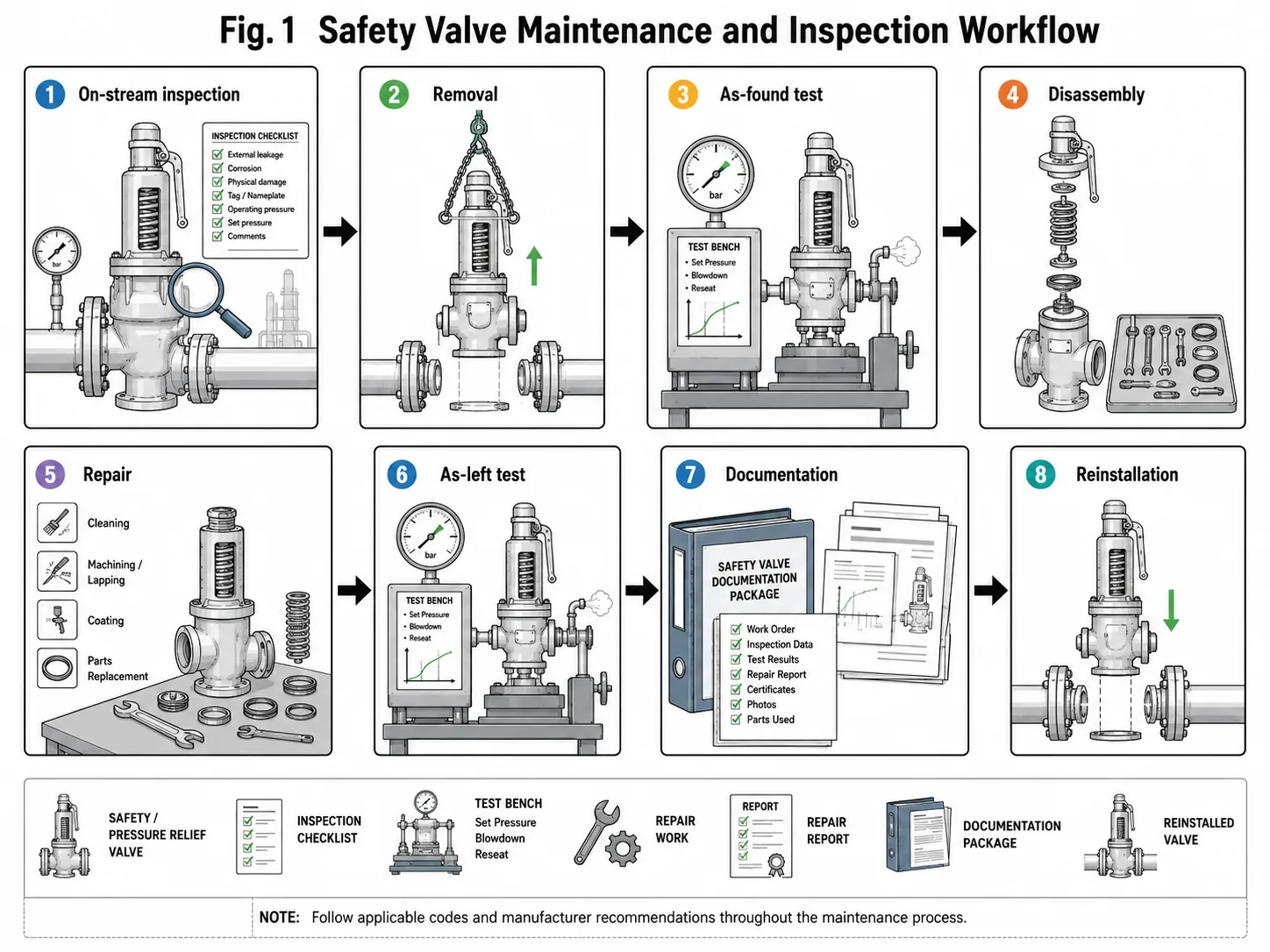
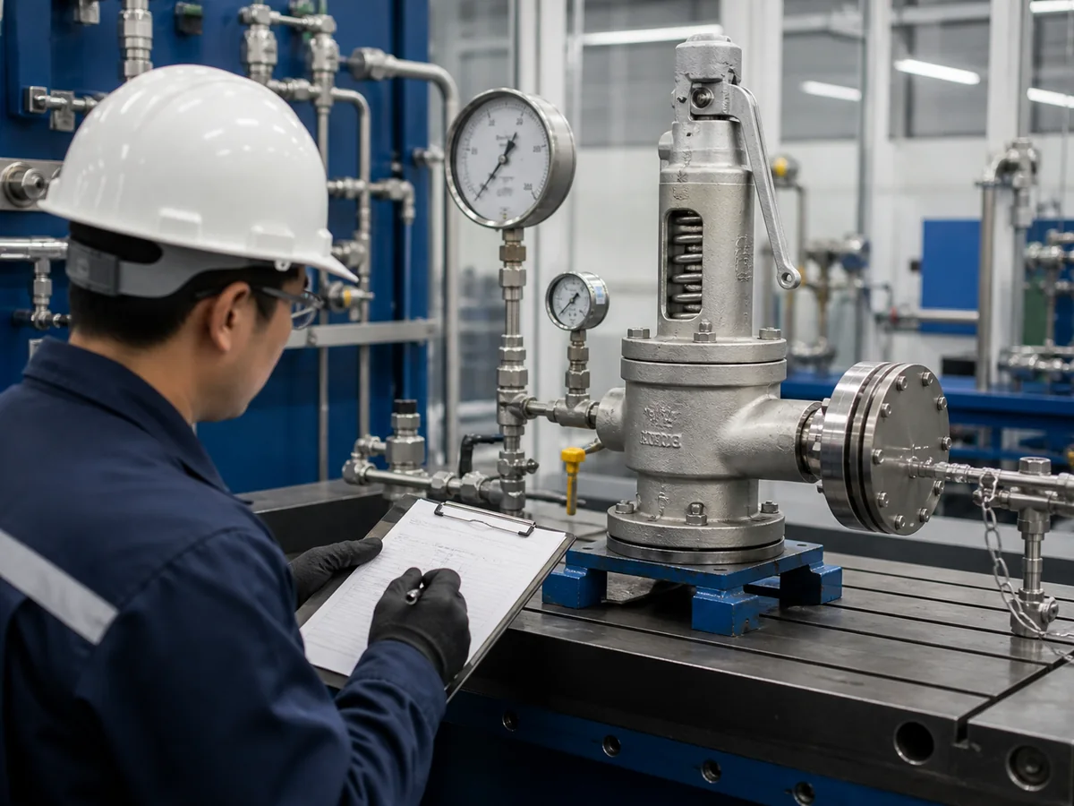
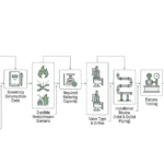
Typical safety valve maintenance workflow from on-stream inspection to documentation and reinstallation.
Why Safety Valve Maintenance Is Different from General Valve Maintenance
Safety Valves Are Final Pressure Protection Devices
A safety valve, pressure relief valve, safety relief valve or PSV is not a normal isolation or control valve. It is installed to protect pressure vessels, boilers, pipelines, tanks and process systems from excessive pressure. During normal operation, the valve may stay closed for long periods. When an overpressure event occurs, it must open at the correct set pressure, pass the required relieving capacity, and reseat after the system pressure is reduced.
This is why maintenance must check more than external appearance. The valve has to maintain its pressure setting, sealing condition, spring force, trim movement, discharge path and documentation integrity. A painted body, intact flange and clean nameplate do not prove that the valve will open and relieve correctly.
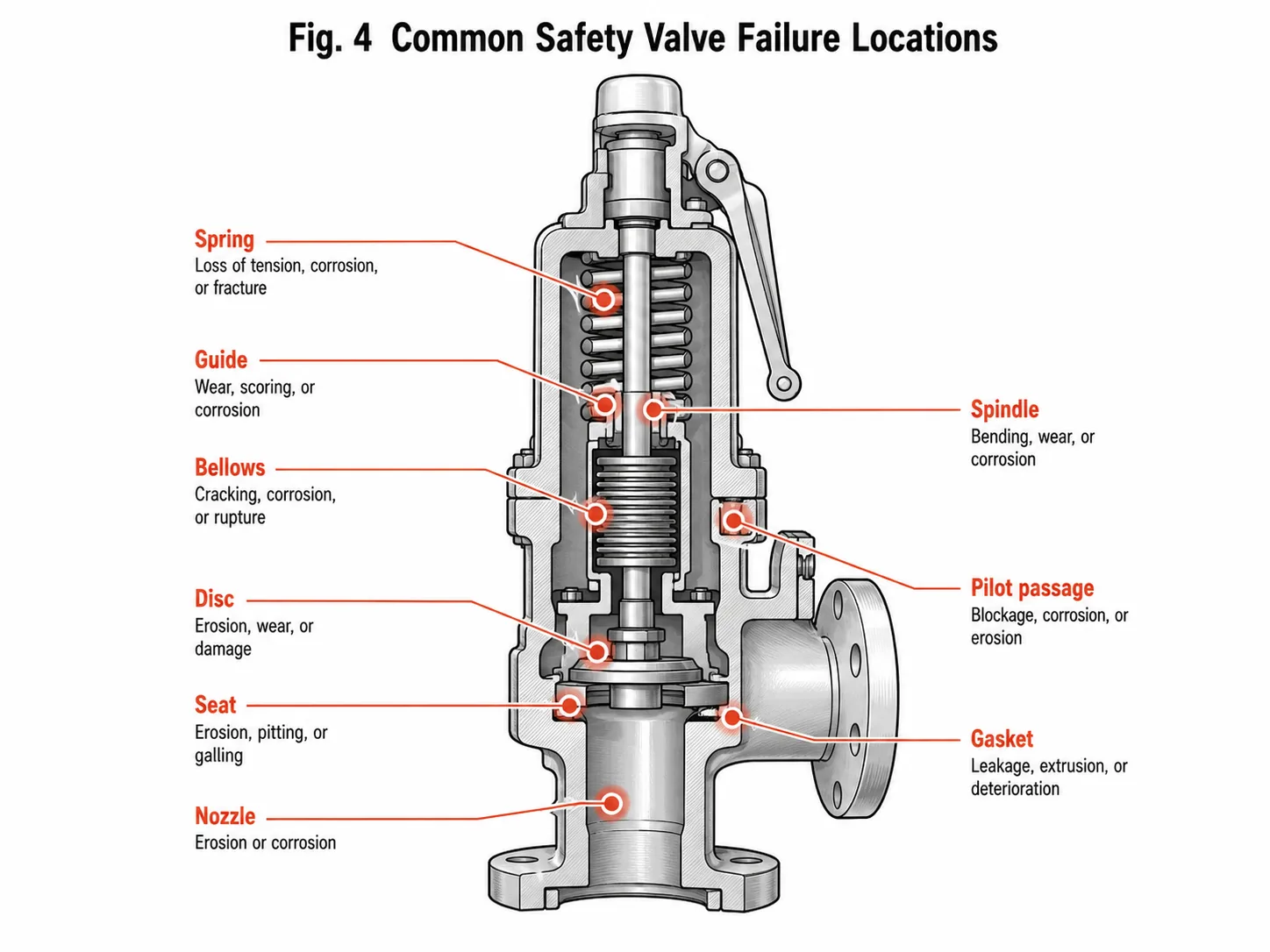
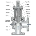
Safety valve assembly diagram showing key components that should be considered during inspection, testing and maintenance review.
Visual Inspection Alone Does Not Prove Set Pressure or Relieving Capacity
On-stream visual inspection is necessary, but it cannot confirm everything. It can reveal external leakage, corrosion, blocked drains, missing seals, damaged discharge piping or incorrect isolation status. It cannot prove the exact opening pressure, seat tightness, spring condition, blowdown behavior, certified capacity or internal trim damage. These require bench testing, internal inspection or engineering review.
Why it matters: a valve may pass a walkdown but fail an as-found test after removal. If the set pressure has drifted, the valve may open too early and disturb production, or open too late and reduce the safety margin. If the seat is damaged, leakage may increase operating cost and emissions. If the certified capacity no longer matches the process duty, the protected equipment may not be adequately protected.
Illustrative maintenance error — correct set pressure, inadequate duty: A replacement valve passed the shop set-pressure and leakage tests, but the protected unit had been debottlenecked and the governing relief load had increased. The maintenance package reused the old valve size without checking the current relief calculation or supported capacity. The valve was mechanically serviceable but no longer proven suitable. Correction: place the replacement on engineering hold, compare required and supported capacity, and update the valve register and datasheet. Prevention: link every capacity-affecting process change to the pressure-relief-device register.
Maintenance Decisions Affect Safety, Compliance, Downtime and Insurance Risk
Safety valve maintenance is also a compliance and documentation issue. Plant teams often need records showing valve tag number, set pressure, test condition, as-found result, as-left result, repair scope, replaced parts, calibration status, seal status and applicable certificate. Missing documentation can delay startup, audit approval, insurance review or equipment handover even if the physical valve has been repaired.
Maintenance planning should therefore consider both technical and administrative risk. If repair records are incomplete, if the valve was repaired by an unqualified shop, or if the nameplate and seal do not match the plant record, the valve may become a compliance problem during inspection.
Project review note: If your plant is preparing for shutdown maintenance, collect valve tag data, service conditions, previous test reports, failure symptoms and required documentation before requesting inspection, repair or replacement review.
What Should Be Checked During an On-Stream Visual Inspection?
External Leakage, Corrosion, Missing Seals and Damaged Parts
On-stream inspection begins with a visual check of the installed valve. Look for leakage around the inlet flange, outlet flange, bonnet, cap, lifting lever, body plug, drain connection and discharge connection. Check for corrosion, missing seal wire, damaged nameplate, broken cap, loose bolting, paint damage, external deposits and signs of overheating or vibration.
External leakage is not always a simple gasket issue. Leakage may come from seat leakage passing through the discharge pipe, damaged trim, incorrect installation stress, vibration, excessive operating pressure close to set pressure or poor post-maintenance assembly. The inspection note should record location, severity, operating condition and whether leakage is continuous or intermittent.
Inlet Piping, Outlet Piping and Support Condition
The valve cannot be evaluated separately from its piping. The inlet line should be short, properly supported and free from visible strain. Outlet piping should not impose excessive load on the valve body. Unsupported discharge piping can create mechanical stress, misalignment, flange leakage, vibration or seat damage after operation. Use the Safety Valve Installation Guide when the walkdown identifies inlet restriction, outlet loading, drainage or support concerns.
What can go wrong: if a safety valve is installed on a long, unsupported inlet line or connected to a heavy discharge pipe without proper support, the valve may chatter, leak or suffer body and flange stress. During maintenance review, piping condition should be treated as part of the valve inspection.
Discharge Pipe, Drain Hole, Rain Cap and Safe Vent Path
The discharge path should be open, safe and correctly directed. Check for blocked outlet piping, closed drain holes, water accumulation, insect nests, corrosion products, damaged rain caps, frozen drains, plugged silencers or modifications to the vent path. For steam and outdoor service, drainage and condensate management are especially important.
If liquid accumulates in the outlet piping, the valve may experience extra back pressure, corrosion, freezing, water hammer or unstable reseating. A blocked drain can turn a simple installation issue into a reliability and safety risk.
Isolation Valves, Car Seals and Lock-Open Status
If isolation valves are installed before or after a safety valve, their operating status must be controlled. Check whether the isolation valve is fully open, locked or car-sealed according to site procedure. Any unauthorized closure can disable the pressure protection function. For changeover systems or spare valve arrangements, confirm that protected equipment always has an available relief path.
Inspection records should not simply say “OK.” They should identify isolation valve status and any seal condition. If a car seal is broken, missing or undocumented, the finding should be investigated before the system continues normal operation.
Pilot Lines, Bellows Bonnet Vent and Remote Sensing Lines
For pilot operated safety valves, check sensing lines, tubing, fittings, filters, pilot vents and tubing supports. A plugged or isolated pilot line can prevent correct pressure sensing. For balanced bellows safety valves, check the bonnet vent. A vented bonnet should not be plugged unless the valve design and manufacturer instructions specifically allow it. A blocked vent can hide bellows leakage or change valve performance.
Condition-monitoring discipline: record the exact valve tag, operating pressure, process state, leak location, discharge-path condition and isolation status. A generic “checked—OK” entry is not sufficient for trend analysis or audit traceability.
Pilot valve may sense wrong pressure or fail to operate
Inspect, clean, test and verify procedure before restart
Safety Valve Inspection Frequency: How Often Should It Be Checked?
Why There Is No Universal Inspection Interval
There is no single inspection interval that fits all safety valves. A valve in clean, dry, non-corrosive gas service may have a different maintenance interval from a valve in dirty vapor, polymerizing service, corrosive liquid, wet steam, sour gas, high-temperature service or frequent lifting service. Inspection frequency should be based on service severity, historical test results, failure history, local regulation, plant risk policy and manufacturer instructions.
Trust point: avoid publishing a universal statement such as “all safety valves must be tested every year.” Some plants may use annual testing; others may use risk-based intervals approved by their mechanical integrity program. The article should explain the decision logic, not invent a fixed rule.
Interval Input
Evidence That May Support the Current Interval
Evidence That Should Trigger Review or Shortening
As-found set-pressure trend
Stable results tied to the same service and test basis
Drift, scatter, repeated adjustment or missing pre-repair results
Seat condition
Clean surfaces and repeatable leakage results
Recurring deposits, pitting, wire drawing or leakage after lift
Service severity
Clean, dry, chemically stable service with controlled temperature
Polymerizing, fouling, corrosive, wet, flashing or high-temperature service
Operating events
No known lifting, pressure excursions or damaging vibration
Actual lift, chatter, fire exposure, water hammer or abnormal process upset
System changes
No change to relief load, inlet branch or discharge system
Capacity increase, control-valve change, new header users, silencer or piping reroute
Documentation quality
Traceable valve identity, test basis, instruments and repair findings
Missing nameplate, unknown parts, undocumented adjustment or inconsistent tag data
Risk-based interval rule: an extension should rely on a documented population of comparable valves and stable as-found evidence—not one clean as-left certificate. When the failure mechanism is not understood, the interval should not be extended merely because the valve was successfully repaired.
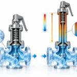
Inspection intervals should be reviewed according to service severity, valve history, corrosion risk, temperature exposure, lifting frequency and process changes.
Clean Service vs Dirty, Corrosive or High-Temperature Service
Clean service usually allows a more stable inspection plan. Dirty service requires more attention to deposits, plugging and seat damage. Corrosive service may shorten the interval because the nozzle, disc, spring, guide, bellows or pilot passages can deteriorate before external damage is obvious. High-temperature service may affect spring relaxation, gasket performance, soft seat aging and bolting condition.
For steam systems, inspection planning should include condensate, erosion, thermal cycling and discharge piping condition. For sanitary systems, maintenance should include cleanability, CIP/SIP exposure, elastomer condition and product-contact documentation.
How Valve History Should Change the Inspection Interval
The strongest inspection interval evidence often comes from the valve’s own history. If repeated as-found tests show stable set pressure, clean internals and acceptable seat tightness, the plant may have confidence in the current interval. If repeated findings show set pressure drift, leakage, corrosion, deposits or damaged seats, the interval should be reviewed and possibly shortened.
For maintenance teams, the as-found test is more valuable than a clean as-left result alone. The as-left test shows the repaired condition; the as-found test shows what actually happened in service.
When Process or Piping Changes Should Trigger Early Inspection
Early inspection or engineering review should be considered when the process medium changes, operating pressure increases, temperature changes, production capacity increases, discharge header is modified, outlet piping is rerouted, a new upstream control valve is installed, or vibration appears after a piping change. These changes may affect inlet pressure loss, back pressure, required relieving capacity or valve stability.
A common plant problem occurs after a discharge header modification. The safety valve may be in good mechanical condition, but increased built-up back pressure causes chatter or delayed reseating during a relief event. The maintenance finding should not be treated only as a “bad valve”; the outlet system needs engineering review.
Management-of-change trigger: changes to relief scenarios, upstream pressure-control equipment, equipment heat input, valve isolation philosophy, discharge-header users, silencers, drains, flare pressure or remote sensing should trigger an engineering review even when the valve itself has not failed.
Service Condition
Inspection Risk
Interval Logic
Shorten Interval When
Record Needed
Clean dry gas or air
Lower, if history is stable
Use plant procedure, regulatory requirement and as-found history
Leakage, set pressure drift or process change appears
Visual inspection, as-found and as-left test records
Steam service
Medium to high
Review condensate, thermal cycling, seat condition and spring exposure
Test record, seat condition, spring inspection notes
Dirty or sticky medium
High
Plan more frequent inspection based on deposits and lifting history
Pilot blockage, seat deposits, slow response, chatter
Internal inspection photos and cleaning records
Corrosive medium
High
Base interval on corrosion mechanism and material history
Pitting, spring corrosion, trim damage, bellows leak
Material review, inspection report, repair scope
High-temperature service
Medium to high
Review spring relaxation, gasket aging and seat material
Set pressure drift, gasket leakage, soft seat damage
Temperature history and as-found results
Frequent lifting service
High
Review each event and inspect seat and guide condition
Repeated lifting, vibration, leakage after lift
Lift history, event report and repair record
Bench Testing: What Happens During Set Pressure and Functional Testing?
As-Found Test Before Cleaning or Adjustment
An as-found test is performed before the valve is cleaned, adjusted or repaired. It records how the valve actually behaved after service. This result can show whether the valve opened near the intended set pressure, whether it leaked before opening, whether it reseated correctly, and whether the inspection interval is reasonable.
Engineering scenario: What problem occurred: a steam safety valve opened below the expected set pressure during operation. Why it happened: the spring had relaxed after long exposure to elevated temperature. Real system cause: the previous maintenance records showed only as-left results, so the plant did not see the gradual drift trend. Corrective action: perform as-found testing, inspect the spring, recalibrate the valve and review spring material. Prevention: keep as-found records and shorten the interval if drift repeats.
Set Pressure Test and Cold Differential Test Pressure
The set pressure test confirms the pressure at which the valve begins to open under test conditions. If back pressure or temperature correction applies, the test may involve cold differential test pressure according to the project procedure and manufacturer instructions. The test condition should be documented clearly because field operating conditions may differ from shop test conditions.
Set pressure affects when the valve begins pressure relief. If it is too low, nuisance lifting and production loss may occur. If it is too high, the protected equipment may not have the intended margin. Adjustment should not be made casually in the field without proper authorization, calibrated equipment and documentation.
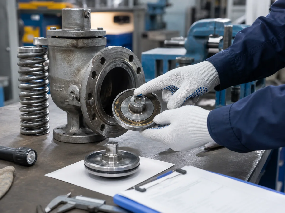
Set pressure testing, seat tightness testing and shell testing confirm different aspects of safety valve condition and should not be treated as the same inspection step.
Blowdown and Reseating Behavior
Blowdown and reseating behavior are important because a safety valve should not continue discharging unnecessarily after the pressure falls, and it should not close so early that system pressure immediately rises again. Poor reseating can cause leakage, cycling, vibration, seat damage and process instability.
For some valve types and services, blowdown settings may not be checked in the same way as set pressure during every shop test. The test scope should follow project requirements, applicable standards and manufacturer instructions. If the valve has a history of chatter or repeated cycling, reseating behavior deserves more attention.
As-Left Test After Adjustment or Repair
An as-left test documents the valve condition after adjustment, repair or reassembly. It confirms that the valve leaves the test bench in an acceptable condition. However, a good as-left test does not erase a poor as-found result. If the as-found result shows serious drift, leakage or damage, the maintenance interval and root cause should still be reviewed.
Why Test Medium, Procedure and Test Bench Condition Matter
Test results depend on test medium, test setup, pressure gauge accuracy, valve orientation, cleanliness, operator procedure and acceptance criteria. A valve that is tested with air in a shop may behave differently in hot steam, liquid, viscous media or dirty service. The test report should state the test condition and should not be interpreted beyond its scope.
Evidence
Primary Use
Required Traceability
Do Not Infer
As-found result
Inspection-interval and in-service condition assessment
Valve serial/tag, test medium, instrument, temperature, back-pressure/test correction and pretest leakage
That the valve was correctly sized for the current process
Set-pressure / CDTP record
Automatic opening adjustment under the approved shop basis
Specified setting, approved correction, actual result, instrument and technician
Full lift, installed stability or capacity
Reseating / blowdown observation
Closing behavior where included in the test scope
Method, pressure values and valve-specific adjustment status
Universal acceptance for every code and valve design
Seat-tightness report
Closed-valve leakage at stated test conditions
Seat type, test medium, pressure, duration, measurement and acceptance basis
Opening setting or relieving capacity
Capacity certificate or manufacturer data
Supported flow performance for the identified model and conditions
Model, orifice, fluid, pressure/temperature basis and applicable certification
That the plant relief calculation is current
Cold differential test pressure boundary: do not create a shop correction from a generic temperature or back-pressure rule. The correction must be tied to the selected valve design, approved engineering basis and manufacturer or code procedure, and the as-left report should distinguish the shop setting from the intended field set pressure.
Bench Test Step
Purpose
What It Reveals
Failure Concern
Record Required
As-found test
Capture valve condition after service
Actual opening pressure and leakage trend
Hidden set pressure drift or seat damage
As-found pressure, leakage note, test medium
External inspection
Check body, bonnet, cap, nameplate and seals
Damage, corrosion, missing seal, wrong tag
Wrong valve identification or uncontrolled adjustment
Inspection checklist and photos
Disassembly inspection
Check internal components
Seat damage, corrosion, spring condition, guide wear
Repeat failure if root cause is missed
Repair report and parts list
Set pressure adjustment
Return opening pressure to specification
Spring and adjustment condition
Incorrect setting or unstable opening
Calibration and adjustment record
Seat tightness test
Confirm leakage condition
Seat and sealing quality
Leakage after reinstallation
Leakage test result and test basis
As-left test
Document final condition
Valve leaves shop in accepted condition
Incomplete repair or missing retest
Final test report and seal record
Seat Tightness Test: How to Judge Safety Valve Leakage
What Seat Tightness Testing Actually Confirms
Seat tightness testing checks the leakage condition of a closed safety valve under specified test conditions. It does not prove that the valve has enough relieving capacity, and it does not replace set pressure testing. It is a leakage verification step, not a complete performance qualification.
For plant engineers, the key question is not only whether leakage exists, but whether leakage is acceptable for the service, seat type, test condition and project requirement. A small amount of leakage may be evaluated differently for metal-seated and soft-seated valves, depending on the applicable test requirement.
Metal Seat vs Soft Seat Leakage Expectations
Metal seats are often used for steam, high-temperature or severe service. They may be more tolerant of heat and particles, but leakage expectations should be defined by the project standard and test basis. Soft seats can improve tight shutoff in compatible clean service, but they may fail if exposed to excessive temperature, incompatible chemicals, particles or repeated cycling.
What can go wrong: choosing a soft seat only to stop leakage may create a new problem if the elastomer is not suitable for the medium or temperature. The valve may pass a shop test and then leak, swell, crack or stick after exposure to real process conditions.
Why API 527 Should Not Be Misread as a Universal Zero-Leakage Requirement
API 527 is commonly referenced for pressure relief valve seat tightness testing, but it should not be treated as a universal “zero leakage” statement for every valve, service and project. The exact edition, scope, test medium, seat type and acceptance basis should be verified before applying it. If a project requires tighter leakage criteria, that requirement should be stated in the RFQ and inspection plan.
For projects that invoke API 527, the report should identify the applicable edition, valve design, seat type, set-pressure range, test medium, test pressure, stabilization period, measurement method and acceptance criterion. API 527 covers seat-tightness methods for applicable conventional, bellows and pilot-operated pressure relief valves; it does not determine the plant relief load, installation suitability or repair interval.
When Leakage Means Cleaning, Relapping, Repair or Replacement
Leakage after maintenance can be caused by dirt on the seat, damaged sealing surfaces, poor lapping, incorrect assembly, damaged soft seat, corrosion, spring force problems or operating pressure too close to set pressure. The corrective action depends on the cause. Cleaning may solve contamination; lapping may restore minor seat damage; trim replacement may be needed for deep damage; replacement may be more practical if the valve is obsolete, severely corroded or no longer suitable for the service.
Engineering scenario: What problem occurred: a gas safety valve leaked after reinstallation. Why it happened: small particles remained on the seat after repair. Real system cause: cleaning and seat tightness verification were not controlled tightly enough during maintenance. Corrective action: remove the valve, inspect the seat, clean the trim and repeat seat tightness testing. Prevention: improve shop cleanliness, protect the inlet and outlet during transport, and document as-left seat tightness before installation.
Seat Type
Typical Concern
Test Consideration
Maintenance Action
Metal seat
Surface damage, corrosion, lapping quality
Leakage acceptance depends on test basis and service
Inspect seat, lap if acceptable, replace trim if damage is deep
Soft seat
Elastomer aging, swelling, extrusion, chemical attack
Check material compatibility and temperature range
Replace seal, verify material, review service condition
Steam service seat
Thermal cycling, erosion, condensate damage
Test result must be interpreted with service conditions
Inspect seat and discharge drainage
Corrosive service seat
Pitting, crevice corrosion, trim attack
Leakage may indicate material mismatch
Review trim material and corrosion mechanism
Internal Inspection: What Parts Usually Fail First?
Nozzle, Disc and Seat Damage
The nozzle, disc and seat are among the most important internal parts because they control sealing. Damage may appear as pitting, erosion, wire drawing, dents, scoring, corrosion or deposits. If damage is minor, relapping may be possible. If damage is deep or caused by corrosion, trim replacement or material review may be necessary.
Spring Corrosion, Relaxation and Set Pressure Drift
The spring controls the closing force in a direct spring loaded safety valve. Corrosion, high temperature, relaxation, wrong material or incorrect adjustment can change the actual set pressure. A spring that looks acceptable externally may still have lost load. If as-found tests repeatedly show drift, the spring and bonnet environment should be investigated.
Guide, Spindle and Moving Part Galling
Moving parts must remain free enough for stable opening and reseating. Galling, deposits, misalignment, corrosion or worn guide surfaces can cause sticking, chatter, delayed opening or poor reseating. Stainless-to-stainless sliding pairs, dirty service and high-temperature operation require careful material and clearance review.
Bellows Fatigue, Cracking or Leakage
In balanced bellows safety valves, the bellows helps reduce back pressure effects and protect the bonnet area from process fluid. Bellows damage may appear as cracking, fatigue, corrosion or leakage into the bonnet. If the bonnet vent shows discharge or the vent is plugged, the finding should be reviewed immediately. A damaged bellows may make the valve behave more like a conventional valve under back pressure.
Pilot Passage Contamination and Seal Damage
In pilot operated safety valves, small passages and sensing lines can be affected by dirt, hydrate, wax, polymer, corrosion products or condensate. A blocked pilot passage may cause delayed opening, unstable dome pressure or failure to reseat. Pilot seals must be checked for chemical compatibility, compression set and temperature exposure.
Component
Typical Degradation Mechanisms
Maintenance Evidence
When Engineering Review Is Needed
Nozzle, disc and seat
Corrosion, erosion, deposits, wire drawing, impact and poor lapping
Photographs, dimensions, lapping/removal record and leakage result
Repeated leakage, deep damage or changed seat geometry
Spring
Corrosion, relaxation, cracking, wrong range or thermal exposure
Identification, condition, free length/load data where required and replacement traceability
Repeated set-pressure drift or unknown spring identity
Guide and spindle
Galling, deposits, misalignment, distortion and clearance change
Visual findings, movement check, dimensions and material pairing
Chatter, delayed opening or repeated sticking
Bellows
Fatigue, corrosion, cracking, deformation and leakage
Inspection method, replacement part identity, bonnet-vent finding and pressure test where required
Vent discharge, unknown back-pressure exposure or recurrent failure
Pilot, seals and sensing lines
Plugging, hydrate/wax/polymer deposits, seal aging, leakage and condensate
Cleanliness findings, filter condition, seal compound, tubing check and functional test
Dirty service, delayed action, unstable dome pressure or changed sensing route
Body, bonnet and bolting
Pressure-boundary corrosion, external environment, gasket leakage and piping load
Surface condition, NDE where required, bolting/gasket traceability and shell test basis
Cracking, wall loss, distortion or unapproved pressure-boundary repair
Engineering scenario: What problem occurred: a pilot operated safety valve showed delayed response during inspection. Why it happened: fine particles accumulated in the pilot passage and sensing path. Real system cause: the medium was not clean enough for the selected pilot configuration without additional maintenance planning. Corrective action: clean and inspect the pilot assembly and verify the sensing line. Prevention: review contamination risk before selection and define filtration, inspection interval or alternative valve type.
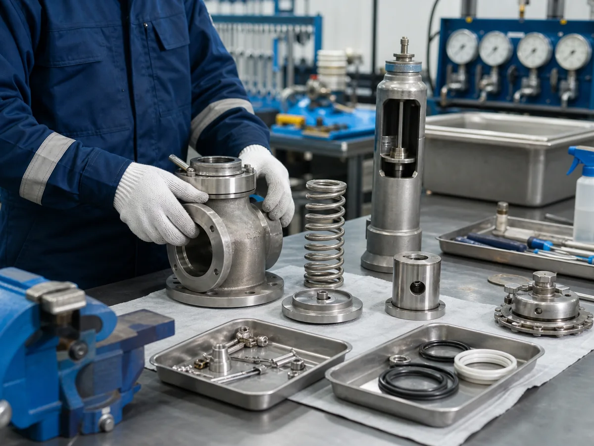
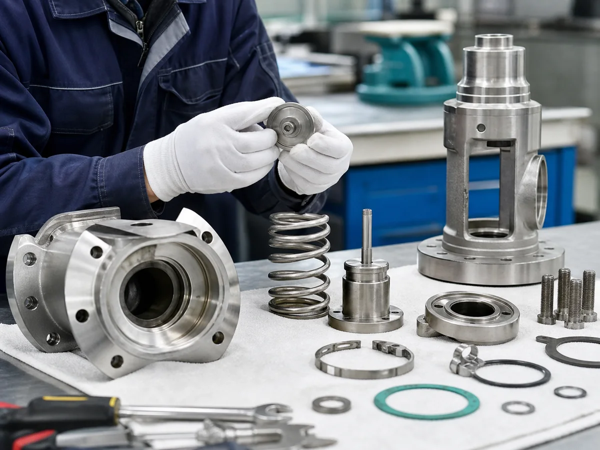
Common safety valve failure points include the seat, nozzle, disc, spring, guide, spindle, bellows, pilot passage and sealing components.
Common Safety Valve Problems and Maintenance Actions
Valve Leaks Before Set Pressure
Leakage before set pressure may be caused by seat damage, dirt on the seat, spring force loss, operating pressure too close to set pressure, damaged soft seat, corrosion, poor installation or discharge back pressure. The maintenance action should not stop at tightening bolts or replacing a gasket. The seat, set pressure and operating margin should be reviewed.
Valve Opens Too Early or Too Late
If the valve opens too early, the cause may be spring relaxation, incorrect adjustment, vibration, damaged internals or testing error. If it opens too late, the cause may be spring over-compression, sticking parts, blocked pilot sensing, corrosion, incorrect cold differential test pressure or unauthorized adjustment. Both cases require test documentation and root cause review.
Illustrative case — correct setting, insufficient capacity:Problem: a repaired valve opened at the specified set pressure, but vessel pressure continued to rise during the governing upset. Cause: production capacity and upstream control-valve flow had increased, while the maintenance decision assumed the original valve remained hydraulically adequate. Correction: verify the current relief scenario, required flow, orifice and supported capacity before returning the system to service. Prevention: connect equipment debottlenecking and control-valve changes to relief-load revalidation.
Valve Chatters, Simmering Occurs or the Disc Vibrates
Chatter and simmering may be caused by oversized valves, excessive inlet pressure loss, unstable process pressure, outlet back pressure, mechanical vibration, poor blowdown behavior or damaged guides. If chatter occurs after a discharge header modification, the root cause may be outlet piping and back pressure rather than the valve alone.
Illustrative case — common-header modification:Problem: one spring-loaded valve began chattering after additional relief devices were connected to a shared header. Cause: the project did not recalculate simultaneous flow, outlet resistance or built-up back pressure. Correction: inspect the disc, seat and guide for chatter damage; reanalyse the header; verify allowable back pressure and any capacity correction for the actual valve design. Prevention: treat every relief-header modification as a management-of-change item and update the pressure-relief-system study before startup.
Valve Does Not Reseat Properly
Poor reseating can be caused by seat damage, debris, wrong blowdown setting, unstable pressure, spring damage, guide wear or discharge system effects. A valve that does not reseat can cause continuous loss of medium, environmental emissions, noise, icing, product loss and maintenance workload.
Valve Fails Bench Test After Removal
A failed bench test should be treated as useful information, not only as a repair task. The result should be compared with prior records to determine whether the inspection interval is too long, service conditions have changed, material selection is unsuitable, or installation conditions are damaging the valve.
Sticking, blocked pilot line, corrosion, wrong CDTP
Inspect moving parts, pilot path and test basis
Repair, clean, recalibrate and verify sensing line
Control contamination and review test procedure
Chatter
Oversizing, inlet loss, back pressure, unstable process pressure
Review sizing, inlet piping, outlet piping and relief scenario
Correct piping, review valve size or valve type
Include piping review in maintenance program
Does not reseat
Seat damage, debris, guide wear, blowdown issue
Inspect seat, guide and reseating test behavior
Clean, repair trim, recalibrate or replace valve
Review service cleanliness and maintenance interval
Repeated test failure
Wrong material, severe corrosion, obsolete design
Compare failure history and service data
Replace valve or redesign selection basis
Use failure history in future procurement review
Maintenance Requirements by Safety Valve Type
Spring Loaded Safety Valve Maintenance Checks
Spring loaded safety valves require inspection of spring condition, seat surfaces, disc, nozzle, guide, spindle, adjustment screw, cap and lifting lever if installed. Spring corrosion and relaxation are important because they can change set pressure. Seat damage and guide wear can affect leakage and reseating.
Pilot Operated Safety Valve Maintenance Checks
Pilot operated safety valves require inspection of both the main valve and the pilot system. The pilot, sensing line, dome chamber, tubing, filters, seals and vent path should be checked. Dirty, sticky or corrosive media require special attention because small pilot passages can plug more easily than the main flow path.
Balanced Bellows Safety Valve Maintenance Checks
Balanced bellows safety valves require inspection of the bellows, bonnet vent and trim condition. If the bellows is cracked or leaking, back pressure compensation may be lost and process fluid may enter the bonnet. A plugged bonnet vent can hide bellows failure and affect valve behavior.
Lever Safety Valve and Boiler Safety Valve Checks
Lever safety valves used in boiler or steam service require attention to lever movement, cap condition, seat condition, spring exposure, discharge piping, drainage and operating test procedures. A try-lever operation, where applicable and permitted, should not be confused with a full set pressure verification.
Sanitary Safety Valve Checks for CIP and SIP Systems
Sanitary safety valves require inspection of product-contact surfaces, elastomers, clamp connections, drainability, dead-leg risk, surface finish and CIP/SIP compatibility. A valve may be mechanically functional but still unacceptable if it creates a cleaning or validation issue.
Valve-type boundary: maintenance findings should feed back into selection. Repeated pilot plugging may justify filtration, a different sensing arrangement or a direct spring-loaded design. Repeated conventional-valve instability under variable back pressure may justify a discharge-system correction or another valve construction. Repairing the same symptom without reviewing the design boundary is not a complete corrective action.
Valve Type
Main Maintenance Focus
Common Risk
Record to Keep
Spring loaded safety valve
Spring, seat, guide, disc, nozzle, adjustment
Set pressure drift, leakage, sticking
As-found / as-left test and repair record
Pilot operated safety valve
Pilot, sensing line, dome seal, main valve seat
Blocked pilot passage, delayed opening
Pilot inspection and functional test record
Balanced bellows safety valve
Bellows, bonnet vent, trim, back pressure effect
Bellows crack, vent blockage, hidden leakage
Bellows inspection and vent condition record
Lever safety valve
Lever movement, cap, seat, spring, discharge path
Improper manual operation or corrosion
Test operation and set pressure verification record
Cleaning failure, seal aging, product contamination
CIP/SIP compatibility and material certificate
When Should a Safety Valve Be Repaired, Recalibrated or Replaced?
Repairable Problems vs Replacement Signals
Some findings can be corrected by cleaning, lapping, replacing soft seats, replacing springs, recalibrating set pressure or replacing gaskets. Other findings may require replacement, especially if the body is severely corroded, the trim is deeply damaged, parts are obsolete, documentation is missing, or the valve no longer has enough certified capacity for the service.
Repair may be suitable for minor defects, while replacement or re-selection should be reviewed when capacity, traceability, severe corrosion or repeated failure becomes a concern.
When Seat Damage Can Be Relapped
Minor seat damage may be repairable by proper lapping if the seating surface remains within acceptable condition. Deep erosion, corrosion, cracking or repeated leakage may require nozzle, disc or seat replacement. If leakage repeats after multiple repairs, the service condition and safety valve material selection should be reviewed.
When Spring, Bellows or Trim Replacement Is Needed
Spring replacement may be needed if corrosion, relaxation, cracking or repeated set pressure drift is found. Bellows replacement may be needed if cracking, leakage or fatigue is identified. Trim replacement may be required when seating surfaces, guide parts or moving components are damaged beyond practical repair.
When Certified Capacity or Service Conditions Have Changed
A valve that can be mechanically repaired may still be unsuitable if the process duty has changed. Higher capacity, different medium, higher temperature, new back pressure, changed outlet header or modified operating pressure may require a new sizing and selection review. Repairing the old valve without confirming the current relieving requirement can create a false sense of safety.
Why Unauthorized Repair Can Create Compliance Risk
Safety valve repair can involve set pressure adjustment, spring replacement, trim work, nameplate control, sealing and certification. If the service or jurisdiction requires authorized repair, the repair organization and documentation must match the requirement. Unauthorized repair can create compliance, insurance and audit risk even if the valve appears functional.
Minimum Return-to-Service Release Sequence
Preserve as-found evidence. Record valve identity, seal condition, leakage, opening result and physical damage before cleaning or adjustment.
Define the authorized repair scope. Confirm which pressure-boundary, trim, spring, bellows, pilot and setting activities the organization is permitted to perform.
Restore the approved configuration. Verify spring range, orifice/trim identity, materials, clearances, seat geometry, lever/cap and pilot parts.
Complete required tests. Perform the approved pressure-boundary, set-pressure, reseating/blowdown and seat-tightness checks applicable to the valve and project.
Restore traceability. Reconcile the nameplate, serial number, repair report, material records, final seal/stamp and test instruments.
Verify the installation. Confirm tag/location, gasket and bolting, orientation, isolation status, inlet/outlet alignment, drains, bonnet vent, sensing line and pilot exhaust.
Close the root cause. Correct contamination, operating-margin, inlet-loss, back-pressure, vibration, material or capacity issues before startup.
Observe after startup. Check leakage, noise, vibration, header pressure and abnormal operation, then update the valve history and next inspection basis.
Finding
Repair Possible?
Replacement Recommended?
Engineering Reason
Documentation Required
Minor seat contamination
Usually yes
Usually no
Cleaning and retesting may restore tightness
Cleaning record and seat tightness test
Minor seat damage
Often yes
Not always
Lapping may be acceptable if damage is shallow
Repair scope and as-left test
Deep corrosion on nozzle or disc
Sometimes
Often yes
Material may be unsuitable or damage too deep
Material review and replacement record
Spring corrosion or drift
Yes, if spring is replaced and recalibrated
Only if parts or design are unsuitable
Spring force controls set pressure
Spring replacement and calibration report
Bellows crack
Yes, if bellows is replaceable
Possible if damage is severe or repeated
Back pressure compensation may be lost
Bellows replacement and pressure test record
Capacity no longer adequate
No, not by repair alone
Yes, or reselect valve
Protection basis has changed
Sizing review and new valve datasheet
Missing nameplate or unclear tag
Only with controlled documentation
Possible
Traceability and compliance are uncertain
Tag verification and engineering approval
Repair or replacement review: If a valve has repeated leakage, unstable set pressure, damaged trim, bellows failure or incomplete records, send the valve tag, service condition, photos and test history to ZOBAI for an engineering review before deciding whether to repair, recalibrate or replace it.
Safety Valve Maintenance Records and Documentation Checklist
Nameplate, Tag Number and Service Data
The maintenance record should identify the valve tag number, serial number, manufacturer, model, inlet and outlet size, pressure class, set pressure, service medium, protected equipment and installation location. If the nameplate is missing or illegible, the valve should not be treated as a normal repair without engineering review.
As-Found and As-Left Test Records
Both as-found and as-left results should be retained. The as-found result shows actual in-service condition. The as-left result shows the final condition after repair, cleaning, adjustment or recalibration. Comparing both helps the plant determine whether the inspection interval and maintenance method are adequate.
Repair Scope and Replaced Parts
The repair record should identify what was inspected, cleaned, adjusted, lapped, replaced or recalibrated. If a spring, seat, disc, nozzle, bellows, gasket, soft seal or pilot component is replaced, the replacement part should be recorded. For critical service, material certificates or traceability records may be required.
Material Certificates and Seat Tightness Reports
Where required by project specification, retain material certificates, PMI records, hardness records, elastomer certificates, NACE statements, shell test reports and seat tightness reports. The document package should match the purchase order and inspection plan, not be requested after the repair is complete.
Seal, Stamp and Traceability Records
After adjustment or repair, the valve may require a new seal or stamp according to the applicable procedure. The seal status should match the maintenance record. If the repair falls under a jurisdictional or authorized repair requirement, the repair organization and scope should be verified before the valve is returned to service.
Repair-authorization boundary: where the owner, jurisdiction or original code route requires National Board VR control, verify the repair organization’s active certificate and scope before work begins. A VR stamp controls an authorized repair process; it does not replace the plant relief calculation, installation review or owner acceptance.
Chain of custody: the valve tag and serial identity should remain linked through removal, transport, shop receipt, disassembly, test reports, parts replacement, final sealing, shipment and reinstallation. A technically correct repair can still be rejected when identity or document traceability is broken.
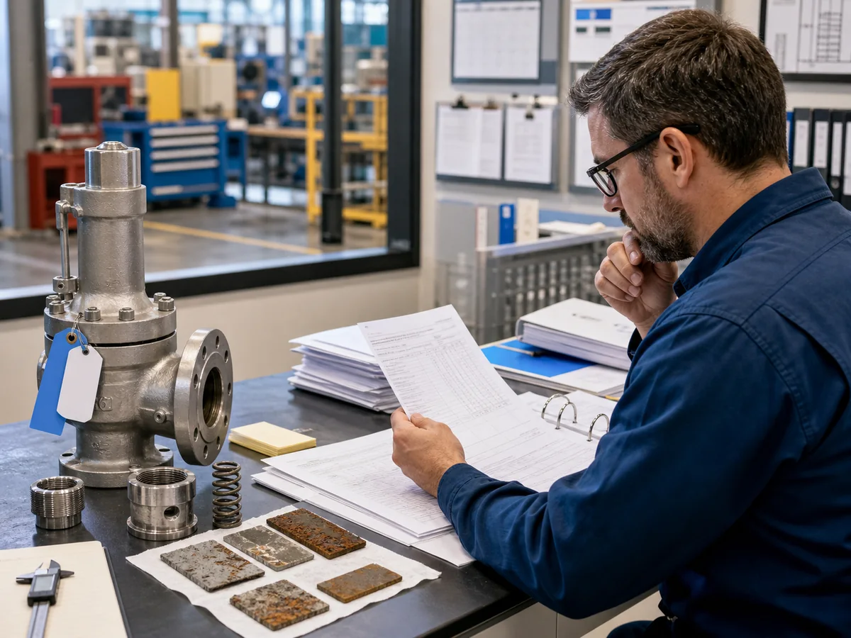
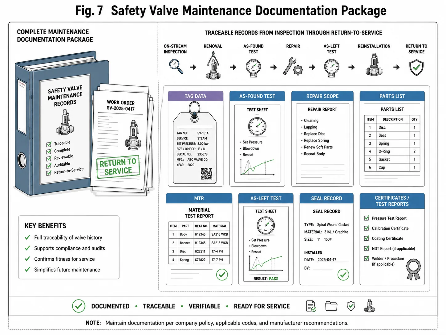
Safety valve maintenance records should remain traceable from inspection and as-found testing through repair, as-left testing, certification and return-to-service.
Record Type
What It Should Include
Why It Matters
Valve identification
Tag, serial number, set pressure, service, location
Prevents wrong repair or wrong installation
As-found test
Opening pressure, leakage, test medium, condition before repair
Shows real in-service performance
Repair report
Cleaning, lapping, replaced parts, adjustment
Provides traceability and root cause evidence
As-left test
Final set pressure and leakage condition
Confirms readiness for return to service
Material records
MTR, PMI, hardness, elastomer certificate if required
Supports material compliance and audits
Seal and authorization
Seal wire, stamp, certificate, repair scope
Supports compliance and prevents unauthorized adjustment
Safety Valve Maintenance Checklist for Plant Teams
Pre-Shutdown Preparation
Before shutdown, prepare the valve list, tag numbers, service conditions, previous test reports, failure history, spare parts requirement, lifting equipment, isolation plan, blind list and documentation requirement. Confirm whether any valves require special handling due to toxic, flammable, corrosive, sanitary, high-temperature or sour service.
Removal and Transport Controls
During removal, protect flange faces and internals from dirt or damage. Do not use the lifting lever, cap or pilot tubing as a lifting point. Record the removed valve location and keep tag traceability. Protect the valve from impact during transport to the workshop.
Shop Inspection and Test Workflow
The shop workflow should include as-found test, external inspection, disassembly if required, cleaning, internal inspection, repair or replacement of damaged parts, recalibration, seat tightness test, as-left test and documentation. Findings should be recorded clearly enough for future interval review.
Reinstallation and Commissioning Checks
Before reinstallation, confirm that the tag, set pressure, flange rating, gasket, bolts, orientation and discharge direction match the plant record. After installation, check for flange leakage, correct isolation valve status, discharge pipe alignment, drain condition, pilot line connection and seal status.
Post-Maintenance Review
After restart, review whether any valve leaked, lifted, chattered or showed abnormal noise. Compare as-found results against previous records. If the same valve repeatedly fails, do not treat each repair as an isolated event. Review process conditions, material, valve type, sizing, back pressure and maintenance interval.
Stage Gate
Release Questions
Required Record
Before shutdown
Are service, hazard, valve population, previous failures, spares and required authorizations known?
Valve register, work scope, isolation plan and document index
Removal
Is the system safely isolated and is valve identity protected?
Removal checklist, tag control and transport condition
Shop receipt
Has the valve been tested as-found before cleaning or adjustment where required?
Receiving record, photographs and as-found result
Repair
Were findings, dimensions, materials and replaced parts recorded within the authorized scope?
Inspection/repair report and part traceability
Final testing
Do the set, reseating/blowdown and seat-tightness results meet the specified basis?
As-left report, instrument identification and final seal
Reinstallation
Is the correct valve installed without isolation, loading, vent, drain or sensing errors?
Installation and pre-startup checklist
Post-startup
Is there leakage, chatter, abnormal noise, header pressure or repeat failure?
Startup observation and interval/root-cause review
Prepare valve register and tag list
Review previous as-found and as-left records
Confirm service medium and hazard condition
Plan isolation and depressurization
Protect flange and trim during removal
Maintain tag traceability during transport
Perform as-found testing before adjustment
Inspect body, bonnet, spring, seat and trim
Record damaged parts and repair scope
Confirm material and seal compatibility
Perform set pressure and seat tightness test
Complete as-left test documentation
Verify seal wire and nameplate information
Check discharge piping and drain before startup
Confirm isolation valve lock-open status
Review abnormal post-startup leakage or noise
RFQ Checklist for Safety Valve Inspection, Repair or Replacement
Process and Valve Data to Send
For a practical inspection, repair or replacement review, send the valve tag, valve type, manufacturer, model, set pressure, inlet and outlet size, flange standard, service medium, operating pressure, operating temperature, relieving temperature and protected equipment information. If the valve has failed, describe the symptom and when it occurred. For a structured data package, use How to Prepare a Safety Valve Datasheet for RFQ.
Test and Certificate Requirements
State whether set pressure test, seat tightness test, shell test, material certificate, PMI, hardness test, NACE statement, elastomer certificate, repair certificate or third-party inspection is required. Documentation should be defined before quotation because it can affect cost and lead time.
Repair History and Failure Symptoms
Include previous test reports, as-found history, repair history, leakage records, photos of damage and notes on recent process or piping changes. A valve that repeatedly leaks after repair may require material, sizing, operating margin or discharge system review.
Spare Parts and Lead Time Review
Spare parts should be reviewed early for shutdown planning. Springs, soft seats, gaskets, bellows, pilot kits, trim sets and special alloy parts may affect lead time. If a valve is obsolete, replacement may be more reliable than repeated repair.
RFQ Item
Information Needed
Why It Matters
Valve identification
Tag, serial number, model, size, set pressure
Prevents wrong quotation or wrong replacement
Service data
Medium, pressure, temperature, corrosion, solids
Supports material and maintenance review
Failure symptom
Leakage, chatter, early opening, late opening, no reseat
Project review CTA: Need help reviewing safety valve inspection, repair or replacement before shutdown? Send ZOBAI your valve tag list, service conditions, set pressure, previous test reports, failure symptoms, photos and documentation requirements. Our engineering team can help review whether a valve should be cleaned, repaired, recalibrated or replaced for further project evaluation.
FAQs About Safety Valve Maintenance and Inspection
How often should a safety valve be inspected?
The inspection interval depends on service severity, valve history, operating conditions, local regulations, plant policy and applicable standards. Clean and stable service may allow a different interval from dirty, corrosive, high-temperature or frequently lifting service. Do not apply a universal interval without reviewing the service and past test results.
What is included in a safety valve inspection?
A practical inspection may include visual inspection, nameplate verification, seal check, inlet and outlet piping review, discharge path review, as-found testing, set pressure testing, seat tightness testing, internal inspection, repair records and as-left documentation.
What is the difference between safety valve inspection and testing?
Inspection is the broader review of condition, installation, documentation and service history. Testing verifies specific functions such as set pressure, leakage or pressure boundary integrity under defined test conditions.
What is an as-found safety valve test?
An as-found test records the valve’s condition before cleaning, adjustment or repair. It helps determine how the valve actually performed in service and whether the maintenance interval is suitable.
What is an as-left safety valve test?
An as-left test records the final valve condition after cleaning, adjustment or repair. It confirms that the valve leaves the test bench in the required condition before return to service.
Why does a safety valve leak after installation?
Leakage after installation may be caused by seat contamination, damaged seating surfaces, gasket leakage, piping stress, wrong operating pressure margin, soft seat damage, corrosion, poor assembly or unstable discharge conditions.
Can a safety valve be repaired instead of replaced?
Yes, if the damage is repairable, parts are available, documentation requirements can be met and the valve is still suitable for the service. Replacement should be considered when the valve is severely corroded, obsolete, repeatedly fails, lacks traceability or no longer meets capacity or service requirements.
Who can repair a safety valve?
This depends on local rules, plant policy and the required certification basis. Some pressure relief valve repairs may require an authorized repair organization or specific quality system. Do not assume any repair shop is acceptable for code-controlled service.
Does a safety valve need seat tightness testing?
Seat tightness testing is commonly required or requested where leakage control matters. The need and acceptance basis depend on the valve type, seat design, project specification and applicable test standard.
What records are required after safety valve maintenance?
Typical records include valve identification, as-found test result, repair scope, replaced parts, calibration result, seat tightness test, as-left test, material records where required, seal status and final inspection report.
What is the difference between set pressure and overpressure during maintenance review?
Set pressure is the specified automatic opening condition. Overpressure is the pressure increase above set pressure available during a relieving event under the applicable design basis. A shop set-pressure test does not by itself demonstrate full lift or capacity at the allowed overpressure.
Why is certified relieving capacity more important than connection size?
Connection size confirms mechanical interface, not the internal flow area, lift or supported flow. A replacement should be checked against the current required relieving capacity and the identified model’s certified or documented capacity.
How does back pressure affect safety valve maintenance decisions?
Back pressure can affect opening, lift, capacity, blowdown and reseating depending on the valve design. Chatter or leakage after an outlet-header change may require system analysis rather than repeated valve repair.
When should a pilot-operated safety valve receive additional inspection?
Additional inspection should be considered after contamination, sensing-line changes, filter blockage, condensate or hydrate events, unstable operation, pilot leakage or a change in exhaust/back-pressure conditions.
What should be checked after a discharge-header modification?
Recheck simultaneous relief assumptions, outlet resistance, superimposed and built-up back pressure, drainage, reaction loads, valve stability and any manufacturer capacity correction. Update the relief-system study before relying on the existing valve.
Does passing API 527 prove that the valve is ready for service?
No. An applicable API 527 test addresses seat tightness under specified test conditions. Return to service also requires correct set pressure, suitable capacity, acceptable internal condition, controlled repair, correct installation and complete traceability.
When is National Board VR repair relevant?
VR repair is relevant when the adopted jurisdiction, owner specification or repair route requires an organization authorized under the National Board program. The organization’s active certificate and scope should be verified before work starts.
What should trigger a root-cause review instead of another routine repair?
Repeated set-pressure drift, recurring seat leakage, chatter, bellows failure, pilot plugging, rapid corrosion, repeated post-startup leakage or a changed process duty should trigger a root-cause review of service, materials, sizing, installation and inspection interval.
Standards and Technical References Note
Safety valve maintenance and inspection should be controlled by the project specification, adopted equipment code, jurisdiction, owner mechanical-integrity program and manufacturer instructions. The references below address different parts of the program and should not be treated as interchangeable.
Reference
Maintenance Role
Scope Boundary
Official Source
API RP 576
Inspection and repair practices for pressure-relieving devices in its covered industries
Use the adopted edition and owner program; it does not replace the protected-equipment code or relief calculation.
Edition and applicability warning: the current API RP 576 edition shown in API’s 2026 effectivity material is the fifth edition, September 2024. The project should still specify the edition actually adopted by the owner or jurisdiction. Do not copy a test tolerance, interval or repair requirement from another plant without verifying its governing basis.
Engineering Review
This article is prepared for technical education and preliminary project discussion. Final safety valve maintenance, inspection, testing, repair and replacement decisions should be reviewed by qualified engineers or authorized inspection personnel according to the service conditions, valve history, applicable standards, plant procedure and local regulations.
Review focus: safety valve maintenance, pressure relief valve inspection, set pressure testing, seat tightness, as-found and as-left records, troubleshooting, repair versus replacement, documentation and RFQ preparation.
Need Safety Valve Maintenance or Replacement Review?
Send ZOBAI your safety valve tag list, process medium, operating pressure, set pressure, temperature, previous test reports, failure symptoms, photos, repair history and documentation requirements. ZOBAI can help review whether the valve should be inspected, cleaned, recalibrated, repaired or replaced for further project evaluation.
Minimum review package: protected equipment and relief scenario, required capacity, current valve datasheet/nameplate, service and relieving conditions, inlet/outlet arrangement, back-pressure basis, as-found/as-left history, repair authorization requirement and photographs of damage.
Suggested RFQ attachments: valve datasheet, P&ID, protected equipment data, previous as-found and as-left test reports, photos of damaged parts, service history, material requirements and certificate checklist. For project communication, contact the ZOBAI engineering team.
Related Engineering Guides
Continue with these focused guides when the broader selection or maintenance review reaches the corresponding application question:
To provide the best experiences, we use technologies like cookies to store and/or access device information. Consenting to these technologies will allow us to process data such as browsing behavior or unique IDs on this site. Not consenting or withdrawing consent, may adversely affect certain features and functions.
Functional
Always active
The technical storage or access is strictly necessary for the legitimate purpose of enabling the use of a specific service explicitly requested by the subscriber or user, or for the sole purpose of carrying out the transmission of a communication over an electronic communications network.
Preferences
The technical storage or access is necessary for the legitimate purpose of storing preferences that are not requested by the subscriber or user.
Statistics
The technical storage or access that is used exclusively for statistical purposes.The technical storage or access that is used exclusively for anonymous statistical purposes. Without a subpoena, voluntary compliance on the part of your Internet Service Provider, or additional records from a third party, information stored or retrieved for this purpose alone cannot usually be used to identify you.
Marketing
The technical storage or access is required to create user profiles to send advertising, or to track the user on a website or across several websites for similar marketing purposes.