
A sanitary safety valve for a CIP or SIP system must satisfy two independent requirements: it must protect the equipment from overpressure, and it must remain compatible with the hygienic process. A polished body and tri-clamp connection do not prove sufficient relieving capacity, cleanability, drainability or validation readiness. The engineering review should cover the protected …

A sanitary safety valve for a CIP or SIP system must satisfy two independent requirements: it must protect the equipment from overpressure, and it must remain compatible with the hygienic process. A polished body and tri-clamp connection do not prove sufficient relieving capacity, cleanability, drainability or validation readiness.
The engineering review should cover the protected equipment, relief scenario, set pressure, required capacity, process medium, CIP chemicals, SIP temperature and cycle frequency, product-contact materials, elastomers, surface finish, dead-space risk, installation orientation, discharge routing, testing and documentation.
Engineering takeaway: Select the valve from the pressure-protection duty first, then verify that the complete installed valve—body, seat, seals, connection, inlet branch and outlet path—can be cleaned, drained, sterilized, maintained and documented for the actual process.
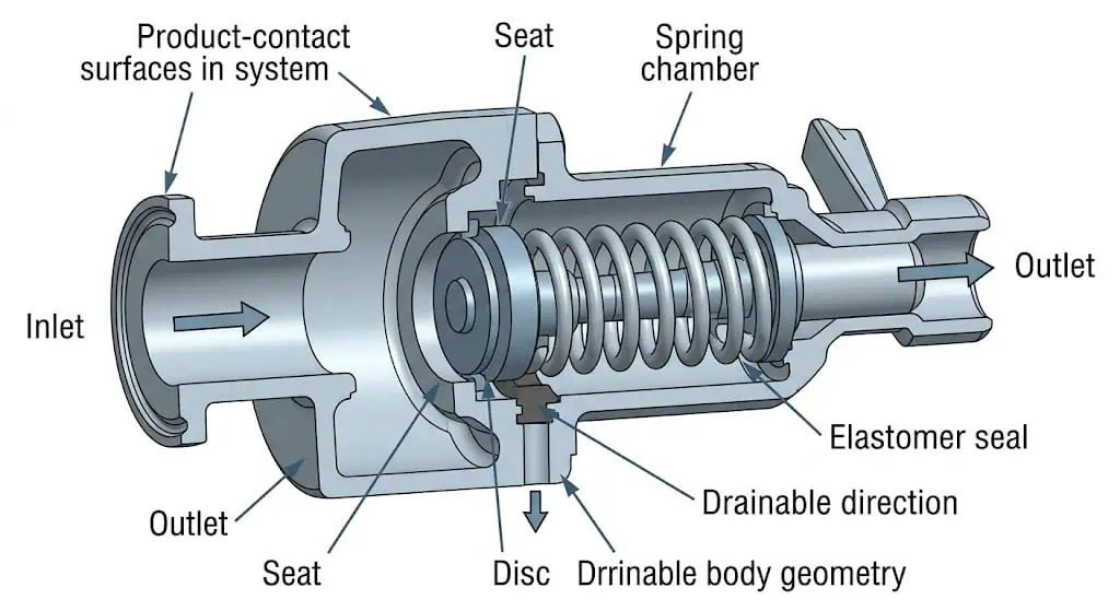
60-Second CIP/SIP Safety Valve Selection Checklist
Protected equipment, tag and pressure-code basis
Credible relief scenario and required relieving capacity
Normal process medium, phase, viscosity and solids
CIP chemicals, concentrations, temperature and exposure time
SIP steam temperature, pressure, duration and cycle frequency
Operating pressure, set pressure and operating margin
Inlet pressure loss and outlet back pressure
Product-contact material and corrosion mechanism
Elastomer grade, temperature limit and chemical compatibility
Surface finish and electropolishing requirement
Cleanability, drainability, dead-space and orientation review
Connection standard, gasket and dimensional compatibility
Set-pressure and seat-tightness test requirements
Material, elastomer, finish and traceability documents
Validation, FAT, SAT, IQ/OQ or audit documentation needs
Maintenance access and post-maintenance requalification
Selection hold point: Do not technically approve the valve when the relief load, fluid phase, CIP/SIP exposure, elastomer requirement or hygienic installation condition is unknown. A supplier can quote a preliminary model, but suitability has not been proven.
What This Guide Covers
This page is the ZOBAI selection guide for sanitary safety valves used in clean-in-place, sterilization-in-place, clean-steam and hygienic process systems. It explains how pressure protection and hygienic design should be reviewed together.
For definition-focused content, see What Is a Sanitary Safety Valve?. For a direct comparison with general industrial valves, see Sanitary vs Industrial Safety Valves. For product models and quotations, see Sanitary Safety Valves.
Pressure-Protection Question
Will the valve open at the approved setting and relieve enough flow under the governing scenario?
Hygienic-Process Question
Can the installed valve be cleaned, drained, sterilized, maintained and documented without compromising the process boundary?
First Confirm the Device Function
The terms sanitary safety valve, sanitary safety relief valve and sanitary pressure relief valve are not always used consistently. A spring-loaded process bypass or pump-protection valve is not automatically an accepted overpressure-protection device for a coded vessel.
| Device Intent | Typical Function | Procurement Question |
|---|---|---|
| Coded or certified safety valve | Protects pressure equipment against a defined overpressure scenario | What code, capacity basis, marking and certification route apply? |
| Sanitary pressure relief / bypass valve | Limits pump or line pressure and may return product to the process | Is it accepted as the required protective device for this equipment? |
| Thermal relief valve | Relieves expansion of blocked-in liquid | What is the thermal expansion case and discharge destination? |
| Pressure regulator or control valve | Controls normal process pressure | Is independent overpressure protection still required? |
Do not rely on the product name. Confirm the valve function, certification, capacity, set-pressure range, fluid phase and intended equipment protection before accepting it as the safety device.
Terminology and certification boundary: “Sanitary,” “hygienic,” “relief valve” and “safety valve” do not define the same thing. A hygienic process valve may control or bypass normal pressure without having the certified capacity, marking or accepted overpressure-protection function required for a pressure vessel. Define the full function in the equipment list and datasheet, and use PRV vs PSV vs Safety Valve vs Relief Valve when project abbreviations are ambiguous.
Typical CIP/SIP and Hygienic Applications
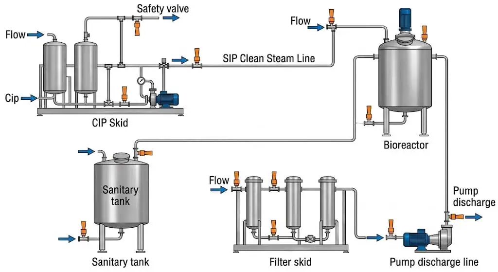
Clean Steam and SIP
Clean-steam generators, SIP headers, sterilization manifolds, autoclave supplies and sterile filter housings.
Product-Contact Vessels
Buffer tanks, formulation vessels, bioreactors, fermenters, holding tanks and hygienic heat exchangers.
CIP Systems
Caustic and acid tanks, CIP supply/return lines, skid discharge, heating circuits and blocked sections.
WFI and Purified Water
Hot loops, storage vessels, thermal expansion sections and clean utility skids.
Food and Beverage
Dairy tanks, brewing, beverage processing, hygienic pump discharge and cleaning circuits.
Hygienic Gas Systems
Sterile air, nitrogen and filtered gas where cleanliness, leakage and discharge routing matter.
Industry-specific selection can be reviewed through Pharmaceutical Safety Valves and Food and Beverage Safety Valves.
Define the Process, CIP and SIP Service Envelope
CIP and SIP are not occasional maintenance events. They are recurring service conditions that can govern corrosion, elastomer life, thermal expansion, seat leakage and validation requirements.
| Operating Mode | Data to Collect | Potential Selection Impact |
|---|---|---|
| Production | Product, phase, viscosity, solids, temperature, pressure and sterility requirement | Capacity, seat, cleanability, material and leakage risk |
| Alkaline CIP | Chemical, concentration, temperature, exposure time and frequency | Elastomer swelling, stress corrosion, finish and seal life |
| Acid CIP | Acid type, concentration, chloride content, temperature and rinse | Localized corrosion, material upgrade and passivation review |
| Sanitizer | Chemistry, oxidizing potential, concentration and contact time | Seal compatibility and metal-surface condition |
| Hot rinse | Temperature, flow, duration and drainage | Thermal cycling and retained-liquid risk |
| SIP | Steam pressure, peak temperature, hold time, cycle frequency and condensate | Elastomer aging, thermal expansion, seat leakage and drainage |
| Cooldown / vacuum risk | Condensation, isolation sequence and possible vacuum condition | Separate vacuum protection or operating procedure may be needed |
The complete design envelope should include startup, shutdown, cleaning, sterilization and abnormal cases—not only the normal production condition.
Operating-mode warning: The governing relief case may occur during production, chemical transfer, hot rinse, SIP steam admission, blocked-in heat-up or cooldown—not necessarily during the normal product run. Confirm the fluid phase for each scenario. A line that contains liquid during production may contain steam, condensate, flashing liquid or a two-phase mixture during cleaning and sterilization.
| Transition | Engineering Risk | Required Review |
|---|---|---|
| Product to alkaline or acid CIP | Reaction, gas generation, seal swelling or unexpected pressure from blocked routing | Sequence, isolation philosophy, chemical compatibility and credible relief scenario |
| CIP rinse to SIP steam | Rapid heating, trapped liquid expansion, condensate and thermal shock | Drainability, valve materials, seal cycle life and steam admission procedure |
| SIP hold to cooldown | Condensation can create vacuum or draw contamination through an unsuitable path | Vacuum-protection philosophy, sterile boundary and controlled cooldown |
| Maintenance to production | Wrong seal compound, incorrect orientation or incomplete documentation | Change control, reassembly verification, calibration and requalification |
Check Pressure Protection Before Hygienic Details
A hygienic valve remains a safety device only when it can protect the equipment under the governing relief scenario.
Identify the Protected Equipment and Relief Scenario
Typical sanitary relief cases may include blocked outlet, pump deadhead, regulator failure, clean-steam overpressure, thermal expansion, heating failure, gas blow-by or another approved scenario. The owner or responsible engineering organization should define the credible case.
Confirm Set Pressure and Operating Margin
Review design pressure or MAWP, normal pressure, CIP pressure, SIP pressure, pump shutoff pressure and process fluctuations. Operating too close to set pressure can cause simmer, leakage or nuisance lifting during cleaning or sterilization.
Calculate Required Relieving Capacity
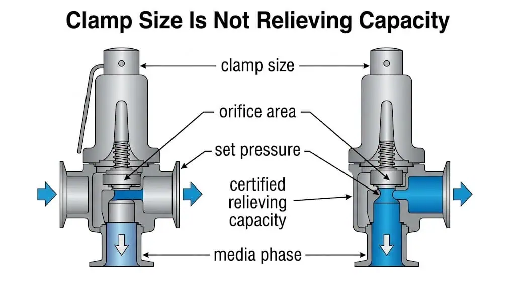
Clamp size does not determine capacity. Required flow depends on the relief scenario, fluid state, pressure, temperature and properties. Compare that load with the manufacturer’s approved or certified capacity under the applicable basis.
Review Inlet Loss and Outlet Resistance
The sanitary branch, gasket, reducer, outlet line, drain connection and closed recovery system can affect stability and capacity. For capacity, see the Safety Valve Sizing and Certified Capacity Guide. For the complete selection process, see the Safety Valve Selection Guide.
Protection boundary: Correct set pressure, a polished body and a sanitary connection are three separate facts. None of them proves that the valve has adequate relieving capacity or that the installed system will open and reseat stably.
For construction selection, see Spring-Loaded vs Pilot-Operated Safety Valves.
| Construction | Potential Advantage | Hygienic and Reliability Boundary |
|---|---|---|
| Direct spring-loaded sanitary valve | Relatively simple force path and fewer small control passages | Still requires verified capacity, operating margin, back-pressure review, cleanable geometry and suitable seat materials. |
| Balanced bellows construction | Can reduce back-pressure influence and isolate selected upper components | The bellows adds a thin flexible component with fatigue, corrosion, cleanability and venting considerations; it is not automatically hygienic. |
| Pilot-operated safety valve | Can provide tight shutoff near set pressure and high capacity in selected clean services | Pilot passages, sensing lines and exhaust routes can retain condensate, CIP residue or product. Suitability must be proven for cleanliness, drainage, sterilization and maintenance. |
| Sanitary bypass or regulating valve | Useful for normal pressure control or pump protection | It is not an accepted substitute for a coded safety device unless the project explicitly verifies the protection and certification basis. |
Spring-Loaded vs Pilot-Operated Designs in Hygienic Service
For the pressure terminology boundary, use Set Pressure, Overpressure, Accumulation and Blowdown.
| Parameter | What It Controls | Sanitary-System Risk if Misunderstood |
|---|---|---|
| Normal operating pressure | Closed-valve margin during production, CIP and SIP | Operating too close to set pressure can cause simmer, leakage or nuisance lifting during temperature and pressure cycling. |
| Set pressure | The specified automatic opening condition under the applicable test or service basis | A correct setting does not prove that the valve can pass the required relief load. |
| Overpressure | Pressure above set pressure used to develop the required lift and capacity under defined conditions | Using an unsupported value can invalidate sizing or capacity comparison. |
| Accumulation | Pressure rise of the protected equipment above its approved pressure boundary during a relieving event | It must be checked against the governing equipment code and scenario, not treated as a synonym for overpressure. |
| Blowdown | Difference between set pressure and reseating pressure | It affects cycling, process loss, sterile-boundary disturbance and post-relief leakage. |
| Inlet pressure loss | Pressure available at the valve inlet while flow develops | Long sanitary branches, reducers or restrictive gaskets can promote chatter and unstable opening. |
| Back pressure | Pressure acting at the outlet before or during discharge | It can affect opening stability, effective capacity, pilot reference pressure and reseating. |
| Required relieving capacity | The flow demand from the governing relief scenario | This is the actual protection requirement and cannot be inferred from clamp size. |
| Certified or documented capacity | The supported flow performance of the identified valve and conditions | It must equal or exceed the project requirement after applicable corrections and limits are considered. |
Pressure Terms Must Use the Correct Reference
Need a Capacity and Hygienic Review?
Send the equipment data, relief scenario, required flow, medium, CIP/SIP envelope and piping layout before selecting the valve by clamp size.
Upload Process DataReview Sanitary Valve OptionsHygienic Design Requirements That Affect Selection
“Sanitary” should describe verifiable design and documentation characteristics, not only appearance.
| Hygienic Requirement | What to Review | Failure Risk |
|---|---|---|
| Cleanability | Can cleaning fluid reach all relevant product-contact surfaces? | Residue or microbial contamination remains after CIP. |
| Drainability | Can product, rinse water and condensate leave the valve and branch? | Hold-up, dilution, corrosion or water hammer. |
| Crevice control | Seat groove, gasket fit, transitions, threads and hidden cavities | Product entrapment and difficult validation. |
| Dead-space control | Inlet branch, body cavity and outlet geometry | Areas receive inadequate cleaning or sterilization. |
| Surface condition | Specified finish, defects, welds, passivation and electropolishing | Cleaning difficulty, corrosion initiation or audit finding. |
| Maintenance access | Disassembly, seal replacement, inspection and reassembly | Long downtime and uncertain post-maintenance hygiene. |
| Boundary isolation | Spring chamber, bonnet, lift device and non-cleanable areas | Contamination path or trapped product. |
A lifting device or pneumatic opening option can support cleaning or function checks on some designs, but it does not replace set-pressure calibration, capacity verification or installed hygienic validation.
Drainability, Dead Space and Installation Orientation
Drainability should be evaluated for the actual installed assembly: equipment nozzle, valve inlet, body, seat area, outlet and downstream piping. A self-draining valve body cannot correct a non-draining branch.
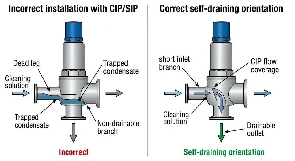
Inlet Branch
Review the branch length, internal diameter, tee or nozzle geometry, slope, welding and connection transition. Use the project-specific ASME BPE, 3-A, EHEDG or owner criteria where applicable; do not apply an unverified universal dead-leg ratio.
Valve Orientation
Confirm the manufacturer’s permitted orientation for both correct valve operation and hygienic drainage. A mechanically possible orientation may retain product or condensate.
Outlet Drainage
Where steam, hot liquid or CIP solution may discharge, provide safe drainage and prevent trapped condensate, backflow and contamination. The discharge path may need hygienic review even when it is not normally product-contact.
Isometric hold point: Resolve branch geometry, valve orientation, outlet slope and drain connection before releasing fabrication. These issues are expensive to correct after installation.
Evidence Needed Before Hygienic Release
Approved valve orientation shown on the installation drawing
Inlet branch dimensions and slope verified from the final isometric
Body cavity, seat pocket and outlet low points reviewed
CIP spray or flow path shown to reach relevant internal surfaces
SIP condensate removal and venting route identified
No gasket intrusion or reducer lip restricting drainage
Shared discharge system assessed for backflow and contamination
Drainability rechecked after any field rotation or spool modification
Surface Finish, Electropolishing and Fabrication Records
The required surface finish should be specified for the exact product-contact parts. Do not assume that “sanitary,” “polished” or “316L” proves a project-specific roughness or electropolished condition.
The RFQ should identify:
- which surfaces are product-contact or clean-utility contact;
- required surface-finish value and measurement method;
- whether mechanical polishing or electropolishing is required;
- acceptable weld finish, heat tint and passivation condition;
- inspection sampling and report format;
- treatment of seat pockets, internal transitions and difficult areas;
- protection of finished surfaces during testing and shipment.
A surface-finish report should be traceable to the actual valve or manufacturing batch when the project requires it. A general brochure value is not the same as order-specific inspection evidence.
| Finish Evidence | What Must Be Defined | Why a Generic Claim Is Insufficient |
|---|---|---|
| Surface-roughness requirement | Exact product-contact areas, parameter, limit, measurement method and sampling plan | A catalogue value may describe a design target rather than the supplied valve. |
| Mechanical polish | Sequence, directional marks, inaccessible areas and final inspection | Visible shine does not prove a uniform measured finish. |
| Electropolishing | Covered components, pre-polish condition, process record and post-treatment inspection | Electropolishing cannot correct deep defects, crevices or poor weld geometry. |
| Passivation | Procedure, chemistry, rinse, drying and record scope | A passivation certificate does not prove that all weld heat tint or embedded contamination was removed. |
| Weld and fabrication record | Weld map, procedure, purge, heat-tint acceptance, inspection and repair history | Base-material certification does not cover fabrication quality. |
Product-Contact Metals and Corrosion Review
316L stainless steel is common, but it is not universally suitable. Review the product, CIP chemistry, sanitizer, chloride exposure, temperature, hold time, drainage and previous plant corrosion experience.
| Material Direction | Potential Use | Engineering Review |
|---|---|---|
| 316L stainless steel | Common hygienic product-contact construction | Verify grade, wetted-parts scope, corrosion exposure, finish and traceability. |
| Higher-alloy stainless steel | More aggressive chloride or cleaning conditions | Confirm corrosion basis, fabrication, welding, lead time and project approval. |
| Nickel alloy such as C-22 | Special product or cleaning chemistry | Define exactly which wetted components require the alloy and why. |
| Coating or lining | Special compatibility cases | Review damage, cleanability, adhesion, inspection and repair limitations. |
Material certificates should identify the material, heat or batch and its traceability to the covered component. Use the Material Certificates Guide and the Safety Valve Material Selection Guide.
Corrosion review: Separate general corrosion, pitting, crevice corrosion, stress-corrosion cracking, galvanic interaction and cleaning-chemical attack. “Use 316L” is not a corrosion analysis.
Review Materials by Component, Not by Body Grade Alone
| Component | Exposure and Failure Mode | Procurement Check |
|---|---|---|
| Body and product-contact cavity | General corrosion, pitting, crevice corrosion, heat tint and retained cleaning solution | Exact grade, heat traceability, finish, welding and passivation scope |
| Nozzle and disc | Seat erosion, chemical attack, galling, deposits and repeated lift damage | Material, hardness/finish where applicable, replacement route and wetted status |
| Guide and spindle | Sticking from residue, corrosion products, thermal expansion or misalignment | Material pairing, clearances, cleanability and lubrication restrictions |
| Spring and upper mechanism | Corrosion from external washdown, steam or leakage; relaxation from temperature | Spring range, environment, protection, material and identification |
| Bellows or pilot components | Fatigue, fouling, condensate retention, blocked passages or chemical attack | Design-specific material, drainage, venting, inspection and spare-part plan |
| Fasteners, clamp and gasket interface | Crevice corrosion, galling, relaxation and dimensional mismatch | Material, pressure-temperature rating, assembly procedure and traceability |
| Lubricants or assembly aids | Migration, product contact, extraction or sterilization degradation | Approved substance, location, quantity and validation documentation |
Elastomers, Seals and SIP Cycle Life
Elastomers and polymeric seats are often the life-limiting components in repeated CIP/SIP service. The same material family can have different formulations, cure systems, fillers, extraction behavior and compliance documentation.
| Seal Direction | Potential Strength | Main Verification |
|---|---|---|
| EPDM | Common in water, steam and many sanitary duties | Exact grade, steam cycles, cleaning chemicals, temperature and compression set. |
| PTFE or modified fluoropolymer | Broad chemical resistance | Sealing mechanics, cold flow, flexibility, grade and traceability. |
| FKM | Useful for selected oils and chemicals | Steam, alkaline and hot-water compatibility can be formulation-specific. |
| FFKM | Broad resistance for demanding chemical service | Exact compound, steam exposure, cost, availability and validation documents. |
| Metal seat | Temperature resistance and no product-contact elastomer at the main seat | Leakage acceptance, surface damage, cleaning and product retention. |
Specify the exact seal compound or approved equivalent, not only “EPDM” or “food grade.” The supplier should confirm:
- product and CIP chemical compatibility;
- SIP peak temperature and hold time;
- expected cycle or replacement interval;
- batch traceability;
- applicable FDA regulation or supplier declaration where required;
- USP biological-reactivity documentation where the project specifically requires it;
- post-maintenance testing and requalification requirements.
Compliance wording: “FDA compliant” and “USP Class VI” are not interchangeable. State the exact required regulation, test chapter, material compound and documentation scope in the purchase specification.
Common Seal Degradation Mechanisms
| Observed Change | Likely Mechanism | Engineering Consequence |
|---|---|---|
| Permanent flattening | Compression set after repeated heat and pressure cycles | Loss of closing margin and seat leakage after SIP. |
| Swelling or softening | Chemical absorption or incompatible cleaning agent | Dimensional change, extrusion, sticking or particle release. |
| Hardening or cracking | Thermal aging, oxidation or repeated steam exposure | Loss of flexibility, leakage and unexpected failure during cycling. |
| Surface erosion or particles | High-velocity cleaning, mechanical damage or formulation weakness | Product contamination and impaired sealing. |
| Excessive extractables or odor | Compound formulation and process exposure | Product-quality or validation concern even when pressure sealing remains acceptable. |
For food-contact rubber articles, a project may reference 21 CFR 177.2600. Pharmaceutical projects may separately request evidence under USP <88>. These are different evidence routes and neither one proves CIP/SIP cycle life, valve cleanability or pressure-relief performance.
Sanitary Connections, Gaskets and Dimensional Compatibility
Tri-clamp is a generic market term and does not always prove dimensional interchangeability. Confirm the exact connection standard, tube outside diameter, ferrule dimensions, pressure-temperature capability, gasket geometry and clamp rating.
Clamp Connection
Review ferrule standard, gasket intrusion or recession, alignment, clamp type and torque or assembly practice. An incorrect gasket can create a crevice or restrict the flow path.
Weld End
Confirm tube specification, wall thickness, orbital-welding requirements, purge, heat tint, inspection, passivation and post-weld finish.
Threaded or Adapted Connections
Threads and adapters may be unacceptable in critical product-contact service because they can introduce crevices and cleaning difficulty. Their use should be justified by the project hygienic risk assessment.
Mechanical fit is not hygienic acceptance. Mixed ferrule systems may clamp together while producing an unacceptable gasket interface or pressure rating.
| Connection Check | Required Evidence | Typical Failure |
|---|---|---|
| Ferrule dimensional standard | Drawing, tube OD, ferrule dimensions and mating standard | Components clamp together but create a step or crevice. |
| Gasket geometry | Exact gasket profile and installed compression | Intrusion restricts flow or recession creates product hold-up. |
| Clamp pressure-temperature rating | Assembly rating for production, CIP and SIP conditions | Loss of preload, leakage or mechanical damage during thermal cycling. |
| Weld-end transition | Tube wall, alignment, orbital-weld procedure and inspection | Internal mismatch, heat tint or non-draining geometry. |
| Adapter or mixed-standard joint | Approved detail drawing and hygienic risk assessment | Hidden crevice, incorrect gasket fit or reduced pressure rating. |
Discharge Routing, Condensate and Back Pressure
The outlet may discharge to atmosphere, a safe drain, collection vessel, closed recovery line or another controlled system. Review personnel safety, product loss, sterile-boundary implications, drainage and back pressure.
Confirm:
- superimposed and built-up back pressure;
- outlet pipe diameter, length and fittings;
- condensate drainage and low points;
- possible backflow into the valve;
- cleaning or sterilization of the outlet path;
- safe handling of hot steam, caustic, acid or product;
- reaction forces and pipe support;
- cross-contamination from a shared discharge system.
Use the Safety Valve Back Pressure Guide and Safety Valve Installation Guide.
Back Pressure Is a Valve-Design Input
| Outlet Condition | Meaning | Possible Effect |
|---|---|---|
| Superimposed back pressure | Pressure present at the valve outlet before the valve opens | Can shift opening behavior or affect pilot reference conditions depending on construction. |
| Built-up back pressure | Pressure generated by discharge flow through the outlet piping | Can reduce stable lift, effective capacity and reseating quality. |
| Variable common-header pressure | Outlet pressure changes as other devices or processes discharge | Can produce unpredictable stability and cross-contamination risk. |
| Condensate or liquid seal | Retained liquid imposes static head or blocks the intended gas/steam path | Can delay discharge, create water hammer and contaminate the valve. |
| Closed recovery system | Discharge is routed to collection rather than freely vented | Requires pressure-drop, drainage, cleaning and backflow analysis. |
Modification trigger: Adding a recovery vessel, filter, hose, silencer, longer outlet, shared header or additional valve to the discharge system requires a new back-pressure and hygienic review—even when the safety-valve tag and set pressure remain unchanged.
Testing, Traceability and Validation Documents
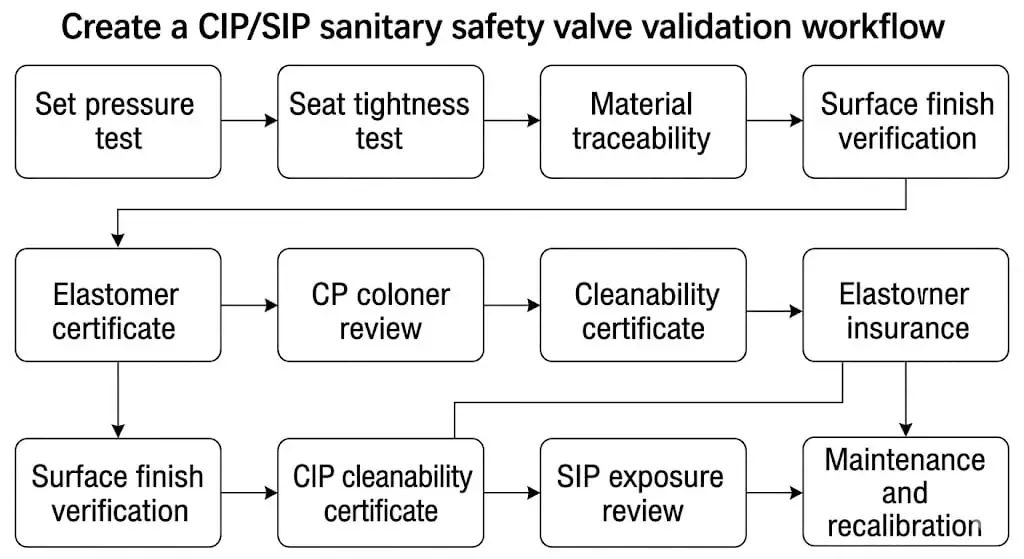
| Document or Test | What It Should Confirm | Common Limitation |
|---|---|---|
| Approved datasheet | Tag, model, service, capacity, materials, connections and document scope | Marketing brochure does not identify the order configuration. |
| Set-pressure calibration | Valve serial number, test basis, result and final sealing | Does not prove hygienic cleanability or capacity. |
| Seat-tightness report | Test medium, pressure, method, leakage and acceptance | Does not prove the relief calculation or surface finish. |
| Material certificate | Grade, heat/batch and traceability to specified components | A body certificate may not cover trim or fasteners. |
| Wetted-parts list | Every metal, polymer, elastomer and lubricant contacting the process | Generic BOM may not match the supplied option. |
| Surface-finish report | Measured areas, method, result and valve/batch traceability | Catalog roughness is not order-specific evidence. |
| Elastomer declaration / certificate | Exact compound, batch and specified regulatory or test status | Material-family name alone is insufficient. |
| CIP/SIP compatibility statement | Reviewed chemicals, temperature, duration and cycle assumptions | “Suitable for CIP/SIP” may omit the actual service envelope. |
| Installation and maintenance manual | Orientation, cleaning, disassembly, replacement and retest procedures | May not include project-specific validation steps. |
API 527 may be specified for seat-tightness testing, but it does not prove hygienic design, pressure-relief sizing or CIP/SIP compatibility. See the API 527 Seat Tightness Test Guide.
For controlled pressure and product documents, review Safety Valve Certificates and Test Reports.
Return-to-Service Controls After Maintenance
- Record the as-found condition.
Document leakage, set condition, seal status, residues, corrosion, orientation and any operating complaint. - Control disassembly and parts.
Identify every wetted part, seal, spring, guide and replacement component by material and batch where required. - Restore the approved configuration.
Use the correct seat geometry, clearances, elastomer compound, surface condition and assembly procedure. - Complete pressure-function testing.
Perform the required set-pressure, functional, pressure-boundary and seat-tightness tests under the approved basis. - Restore hygienic condition.
Clean, rinse, dry, passivate or otherwise treat the valve as required without contaminating finished surfaces. - Verify installation.
Confirm orientation, gasket fit, drainability, inlet/outlet routing and absence of transport or assembly damage. - Close documentation and change control.
Update the serial/batch record, final seal, maintenance report and any FAT/SAT or qualification documents affected by the work.
Where the valve is part of ASME-coded pressure equipment and the jurisdiction requires an accredited repair route, confirm whether National Board / NBIC and VR authorization apply. This repair authorization addresses pressure-relief-valve repair controls; it does not by itself prove hygienic requalification.
How to Control Hygienic and Compliance Claims
Statements such as “ASME BPE,” “3-A,” “EHEDG,” “FDA,” “USP Class VI,” “PED” or “CE” can refer to very different forms of evidence. Procurement should ask what the claim actually covers.
| Claim Type | Evidence to Request | Key Scope Question |
|---|---|---|
| Designed with reference to a standard | Drawing, specification or manufacturer declaration | Which clauses and which product-contact components? |
| Material declaration | Supplier declaration tied to exact compound or material | Does it cover the actual seal grade and batch? |
| Third-party test | Test report, sample identification and method | Is the supplied model represented by the tested sample? |
| Product certification | Certificate, issuing body, model scope and validity | Does it include this size, option, material and manufacturing site? |
| Order-specific inspection | Serial/batch report and acceptance record | Can it be traced to the supplied valve? |
Publishing rule: Do not display a hygienic or regulatory logo beside a valve unless ZOBAI has verified permission to use the mark and the certificate scope covers the exact product being promoted.
Evidence hierarchy: A logo or brochure statement is the weakest project evidence. Prefer an order-specific configuration drawing, exact material/compound identification, certificate scope, test report and serial/batch traceability that can be matched to the supplied valve.
Illustrative Engineering Cases
Fictional training example — not project data
Case 1: Correct Clamp Size, Insufficient Relief Capacity
Problem: A CIP skid required a 1.5-inch clamp connection. The quoted valve fitted the piping but could not pass the approved pump-deadhead relief load.
Cause: The valve was selected from clamp size and set pressure without comparing the calculated required capacity with the manufacturer-supported flow area and capacity.
Correction / prevention: Re-establish the governing relief case, select the required orifice and supported capacity, and only then coordinate the sanitary connection, inlet loss and outlet routing.
Fictional training example — not validation evidence
Case 2: SIP Leakage Caused by Seal-Service Mismatch
Problem: The valve began leaking after repeated SIP cycles even though the product itself was compatible with the selected seal family.
Cause: The RFQ did not define steam temperature, hold time, condensate exposure or cycle frequency. The exact elastomer compound hardened and lost sealing recovery.
Correction / prevention: Review the exact compound against product, every CIP chemical and the full SIP cycle; replace and retest the valve; establish a controlled replacement interval based on service history.
Fictional training example — not validation evidence
Case 3: Valve Passed Pressure Test but Failed Drainability Review
Problem: A clean-steam valve passed pressure testing, but the installed inlet branch and outlet retained condensate and failed the drainability review.
Cause: The supplier’s valve body was evaluated in isolation. The equipment nozzle, branch length, field orientation and outlet low point were not reviewed as one installed assembly.
Correction / prevention: Revise the branch and outlet geometry before qualification, confirm the manufacturer-approved orientation, and update drawings, drainability checks and commissioning records.
Fictional training example — not validation evidence
Case 4: Recovery Header Modification Increased Back Pressure
Problem: A sanitary safety valve became unstable after its outlet was connected to a longer shared recovery header. Condensate also migrated back toward the valve during shutdown.
Cause: The project treated the change as a piping and product-recovery improvement but did not recalculate built-up back pressure, simultaneous discharge or drainability.
Correction / prevention: Reanalyse the complete outlet system, verify the valve manufacturer’s back-pressure limits, provide controlled drainage and prevent backflow. Any recovery-header modification should trigger both pressure-relief and hygienic change control.
When Final Selection Must Be Held
Device Function Is Unclear
The proposed valve may be a process bypass device rather than the required safety valve.
Required Capacity Is Unknown
Clamp size and set pressure do not prove adequate pressure protection.
CIP/SIP Envelope Is Incomplete
Chemical concentration, temperature, duration or frequency is missing.
Elastomer Compound Is Unidentified
A generic material-family name does not prove chemical or steam-cycle suitability.
Drainability Is Not Demonstrated
The valve, inlet branch or outlet can retain liquid or condensate.
Connection Standard Is Ambiguous
The clamp may assemble but produce a crevice, gasket mismatch or wrong pressure rating.
Compliance Claim Is Unverified
The quoted certificate does not clearly cover the supplied model and options.
Validation Documents Are Missing
The project cannot trace materials, seals, finish or tests to the supplied valve.
| Technical Hold Point | Minimum Release Evidence |
|---|---|
| Pressure-protection basis | Approved relief scenario, required capacity, pressure terms and valve performance data |
| CIP/SIP service envelope | Chemical list, concentrations, temperatures, durations, cycle frequency and transition conditions |
| Hygienic geometry | Approved drawing/isometric showing orientation, branch, dead-space control and drainage |
| Materials and seals | Exact wetted materials, elastomer compounds, batch/heat traceability and compatibility review |
| Compliance claims | Certificate or declaration tied to the exact model, size, material, option and manufacturing site |
| Return to service | Calibration, seat test, cleaning, final seal, installation check and completed change-control records |
Ten-Step Sanitary Safety Valve Selection Workflow
- Define the protected equipment and device function.
Confirm whether a coded safety valve, thermal relief valve or process bypass valve is required. - Identify the governing relief scenario.
Establish the approved flow load and fluid state. - Define the complete process and CIP/SIP envelope.
Include chemicals, temperatures, hold times and cycle frequency. - Verify set pressure, capacity and back pressure.
Use manufacturer-approved or certified data where required. - Review hygienic geometry.
Check cleanability, dead space, crevices and boundary isolation. - Review the installed drainability.
Assess the equipment nozzle, valve orientation, outlet and drains together. - Select metals, elastomers and gaskets.
Use exact materials and compounds tied to the service envelope. - Define connections, finish and fabrication controls.
State standards, dimensions, surface requirements and inspection. - Define tests, certificates and validation records.
Agree the document index before purchase. - Approve the complete supplied configuration.
Align datasheet, drawing, nameplate, BOM, certificates, test reports and manuals.
Deviation control: A supplier substitution involving valve type, orifice, elastomer compound, surface finish, ferrule standard, seat construction, pilot arrangement or documentation scope should be returned for engineering and quality approval. “Equivalent” is not an acceptable disposition without evidence against the approved service envelope.
RFQ Checklist for Sanitary Safety Valves
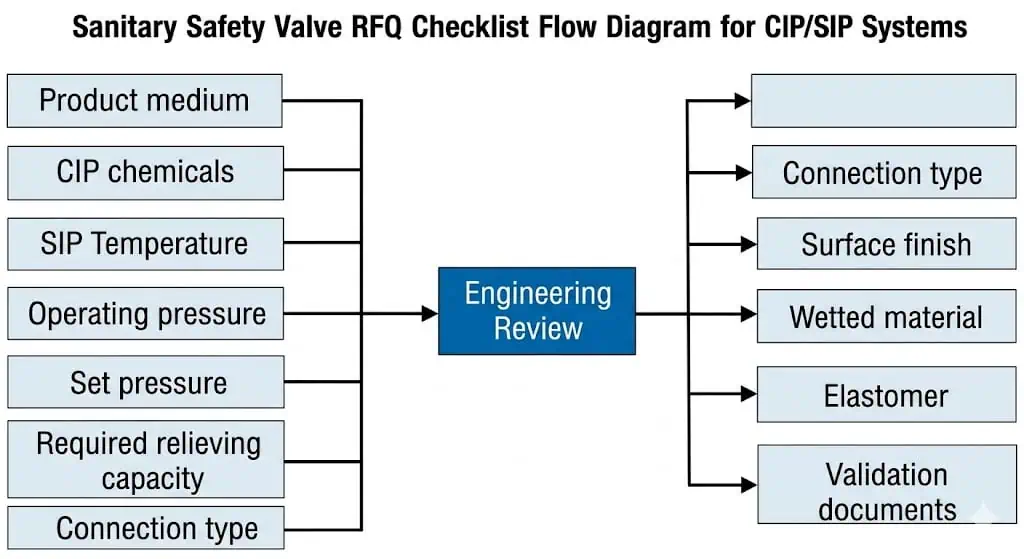
| RFQ Section | Information to Provide |
|---|---|
| Equipment and pressure basis | Equipment tag, MAWP/design pressure, operating pressure, set pressure and applicable code. |
| Relief scenario and capacity | Governing case, required flow, units, fluid phase, relieving pressure and temperature. |
| Process medium | Composition, viscosity, solids, foaming, crystallization, product-contact and sterility requirements. |
| CIP | Every chemical, concentration, temperature, exposure time, rinse and cycle frequency. |
| SIP | Steam pressure, peak temperature, hold time, cycles and condensate condition. |
| Installation | P&ID, isometric, connection standard, orientation, slope, drains and outlet destination. |
| Materials and finish | Wetted metals, elastomer compounds, gasket, finish, electropolish and passivation. |
| Testing | Set pressure, pressure-boundary test, seat tightness and inspection/witness points. |
| Documents | Datasheet, drawing, capacity data, MTR, wetted-parts list, finish, elastomer, test and validation records. |
| Compliance | Exact standard, edition, product scope and certificate or declaration required. |
| Maintenance and requalification | Spare seals, replacement interval assumptions, disassembly controls, post-maintenance tests, cleaning and change-control requirements. |
| Supplier assumptions and deviations | Written list of all assumed data, capacity corrections, material substitutions, excluded documents and certificate limitations. |
Recommended attachments include the P&ID, process datasheet, relief calculation, CIP/SIP cycle description, chemical list, piping layout, hygienic design specification and validation document checklist.
Use How to Prepare a Safety Valve Datasheet for RFQ to convert this checklist into a controlled purchase specification. Unknown data should be marked “to be confirmed”; it should not be inferred from a photograph, old tag or connection size.
Common Sanitary Safety Valve Selection Mistakes
Selecting by Clamp Size
The valve fits the line but may have insufficient or unverified capacity.
Assuming “316L” Is Enough
Corrosion, finish, traceability and all wetted components remain unverified.
Specifying “Food-Grade EPDM”
The exact compound, SIP life and chemical compatibility are unknown.
Reviewing the Valve but Not the Branch
A hygienic valve on a non-draining dead-space branch can still fail validation.
Ignoring the Outlet
Condensate, back pressure, hot discharge or contamination can create new risks.
Using a Relief Valve as a Coded Safety Valve
The device may not have the required capacity or certification basis.
Requesting Documents After Manufacture
Traceability or finish evidence may be unavailable or expensive to reconstruct.
Publishing Unverified Compliance Logos
The product or option may fall outside the actual certificate scope.
Common Symptoms and First Engineering Checks
| Symptom | Likely Causes to Review | First Action |
|---|---|---|
| Leakage after SIP | Compression set, seat contamination, thermal distortion, operation close to set pressure | Isolate under procedure, preserve as-found evidence and perform approved inspection/testing. |
| Chatter during CIP or process upset | Inlet loss, oversized valve, flashing, outlet back pressure or unstable source pressure | Review the relief scenario, inlet/outlet system and mechanical damage before reuse. |
| Pitting or rust staining | Chlorides, acid chemistry, heat tint, poor passivation, retained solution or mixed metals | Identify the corrosion mechanism and inspect all wetted components—not only the body. |
| Delayed pilot response | Blocked sensing passage, condensate, crystallized product or incompatible seal | Clean and test the pilot circuit and reconsider whether the design suits the medium. |
| Retained condensate | Wrong orientation, non-draining branch, outlet low point or blocked drain | Correct the installation geometry before qualification or return to service. |
| Audit documentation mismatch | Generic certificates, wrong batch, undocumented substitution or incomplete BOM | Hold release until the supplied serial/batch configuration is traceable. |
For the broader inspection program, use the Safety Valve Maintenance and Inspection Guide.
Standards and Authoritative References
Hygienic standards and pressure-relief standards address different parts of the selection. The project specification should identify the applicable edition and scope.
| Reference | Role in This Topic | Official Link |
|---|---|---|
| ASME BPE | Bioprocessing and high-hygiene equipment requirements covering materials, design, fabrication, inspection, testing and certification | ASME official page |
| 3-A Sanitary Standards | Sanitary design and fabrication criteria for food, dairy and related product-contact equipment | 3-A official catalogue |
| EHEDG Guideline 8 | Risk-based hygienic design principles for food equipment and installations | EHEDG official page |
| API 520 Part I | Sizing and selection of pressure-relieving devices in covered process-industry applications | API official page |
| API 520 Part II | Installation and engineering analysis of pressure-relieving-device installations | API official page |
| ISO 4126-1 | General requirements for safety valves where the ISO route applies | ISO official page |
| USP <88> | In-vivo biological-reactivity testing for specified polymeric materials; use only where the project requires this evidence | USP official chapter |
| ASME BPVC Section XIII | Overpressure-protection rules for covered pressurized equipment and pressure-relief devices | ASME official page |
| API 527 | Seat-tightness test methods for covered pressure-relief-valve designs; not a hygienic or capacity standard | API official overview |
| 21 CFR 177.2600 | US food-contact provisions for specified rubber articles intended for repeated use | eCFR official text |
| National Board VR / NBIC | Authorized pressure-relief-valve repair route where required by the code and jurisdiction | National Board official page |
Standards boundary: Hygienic design guidance does not replace safety-valve sizing or pressure-equipment rules. Pressure certification does not prove cleanability or product-contact suitability. Both sides must be reviewed.
Edition and scope note: The official ASME page currently lists BPE-2026, the 3-A catalogue includes current and historical standards, and EHEDG lists Guideline 8 Fourth Edition dated December 2025. A project should still state the adopted edition and exact scope rather than automatically applying the newest publication to an existing qualification package.
FAQ About Sanitary Safety Valves for CIP and SIP Systems
What is a sanitary safety valve?
It is an automatic pressure-relief device intended for hygienic or clean process systems. In addition to pressure protection, the selected design may need cleanable product-contact surfaces, suitable sanitary connections, drainability, compatible seals and traceable documentation.
How do you select a sanitary safety valve for CIP and SIP?
Confirm the protected equipment, relief scenario, required capacity, process medium, CIP chemicals, SIP temperature and cycles, back pressure, hygienic geometry, materials, elastomers, connections, installation and required validation documents.
Does a tri-clamp connection make a valve sanitary?
No. The connection is only one feature. Internal geometry, cleanability, drainability, surface finish, seal design, material traceability and the installed branch must also be reviewed.
Does clamp size determine relieving capacity?
No. Capacity depends on the relief scenario, set and relieving pressure, flow area, lift, fluid phase, temperature, back pressure and manufacturer performance data.
Can every sanitary safety valve be cleaned in place?
No. Cleanability depends on valve design, seat and cavity geometry, cleaning coverage, lifting arrangement, orientation, piping layout and the actual CIP cycle.
Can every sanitary safety valve be sterilized in place?
No. The valve and all seals must be verified for the SIP pressure, temperature, hold time, condensate and cycle frequency.
Is 316L stainless steel always suitable?
No. Suitability depends on the product, CIP chemistry, chloride exposure, sanitizer, temperature, drainage, surface condition and corrosion mechanism.
Which elastomer is best for SIP?
There is no universal best material. The exact compound must be checked against steam, product, every cleaning chemical, temperature, cycle frequency, sealing mechanics and required documentation.
Why is drainability important?
Retained product, rinse water or condensate can increase contamination, dilution, corrosion, water-hammer and validation risks.
What documents should be requested?
Typical documents include the approved datasheet, drawing, capacity data, calibration and seat-tightness reports, material certificates, wetted-parts list, surface-finish report, elastomer documentation and CIP/SIP compatibility information.
Does API 527 prove that a sanitary valve is suitable for CIP/SIP?
No. API 527 addresses seat-tightness testing. It does not prove hygienic design, cleanability, drainability, material compatibility or required relieving capacity.
What is the difference between set pressure and overpressure in a sanitary safety valve?
Set pressure is the specified automatic opening condition. Overpressure is the pressure rise above set pressure used to develop the required lift and capacity under defined conditions. Neither value should be selected only from the clamp size or hygienic connection.
How does back pressure affect a sanitary safety valve?
Back pressure can affect opening stability, effective capacity, pilot reference pressure, blowdown and reseating. Closed recovery lines, shared headers, condensate and filters should be reviewed as part of the installed relief system.
Why can a sanitary safety valve leak after SIP?
Common causes include elastomer compression set, thermal aging, seat contamination, retained condensate, thermal distortion, corrosion and operation too close to set pressure. The as-found condition should be preserved before repair.
Can a pilot-operated safety valve be used in a CIP or SIP system?
Only when the pilot, sensing line, exhaust route, seals and internal passages are verified for the product, cleaning chemicals, steam cycle, drainage and maintenance plan. A pilot-operated design is not automatically hygienic.
What must be checked after a seal or seat is replaced?
Confirm the exact material and batch, approved assembly, set pressure, functional response, seat tightness, hygienic cleaning, orientation, drainability, final sealing and any qualification or change-control records affected by the maintenance.
Does FDA or USP documentation prove CIP/SIP suitability?
No. Food-contact or biological-reactivity documentation addresses a specific material and evidence scope. It does not prove valve cleanability, drainability, steam-cycle life, certified relieving capacity or installed-system performance.
How often should a sanitary safety valve be inspected or recertified?
The interval depends on the applicable code, owner program, process risk, CIP/SIP severity, seal history, corrosion, cycling, maintenance findings and local jurisdiction. A universal interval should not be copied without a documented basis.
Review the Pressure Duty and Hygienic Duty Together
Send the P&ID, relief basis, process medium, CIP chemicals, SIP conditions, connection standard, surface-finish requirement, elastomer requirement and validation document list for a sanitary safety valve review.
Upload CIP/SIP Project Data Request a Sanitary Safety Valve Quote View Sanitary Safety Valves





Comments
Kesari Alloys
The detailed engineering review you outlined is essential, particularly the emphasis on assessing the relief scenario and installation orientation. In my experience, overlooking the discharge routing can lead to serious operational risks. Have you encountered specific cases where inadequate drainage caused failures in CIP or SIP systems? It would be beneficial to share some examples or lessons learned from those incidents.