
Safety Valve Selection & Back-Pressure Review A bellows balanced safety valve should be reviewed when outlet back pressure could materially change the force balance, opening stability, capacity or blowdown of a conventional spring-loaded valve. The bellows can reduce selected outlet-pressure effects, but it does not remove the need to verify the governing relief case, required …

Safety Valve Selection & Back-Pressure Review
A bellows balanced safety valve should be reviewed when outlet back pressure could materially change the force balance, opening stability, capacity or blowdown of a conventional spring-loaded valve. The bellows can reduce selected outlet-pressure effects, but it does not remove the need to verify the governing relief case, required capacity, total back pressure, bellows limits, materials, inlet pressure loss, outlet resistance and manufacturer-specific certified data.
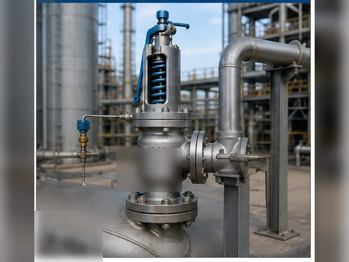
Quick Selection Answer
Start by defining the protected equipment and governing relief scenario. Then establish the medium and phase, required relieving capacity, relieving pressure and temperature, set pressure, superimposed back pressure, built-up back pressure and discharge destination. Only after those inputs are available should the engineer compare a conventional spring-loaded valve, a bellows balanced safety valve and, where relevant, a pilot-operated design.
A balanced bellows valve is not automatically suitable merely because a system has back pressure. The selected manufacturer must confirm allowable total back pressure, capacity correction, bellows pressure and temperature limits, material compatibility, blowdown behavior and the adopted code basis.
What a Bellows Balanced Safety Valve Changes
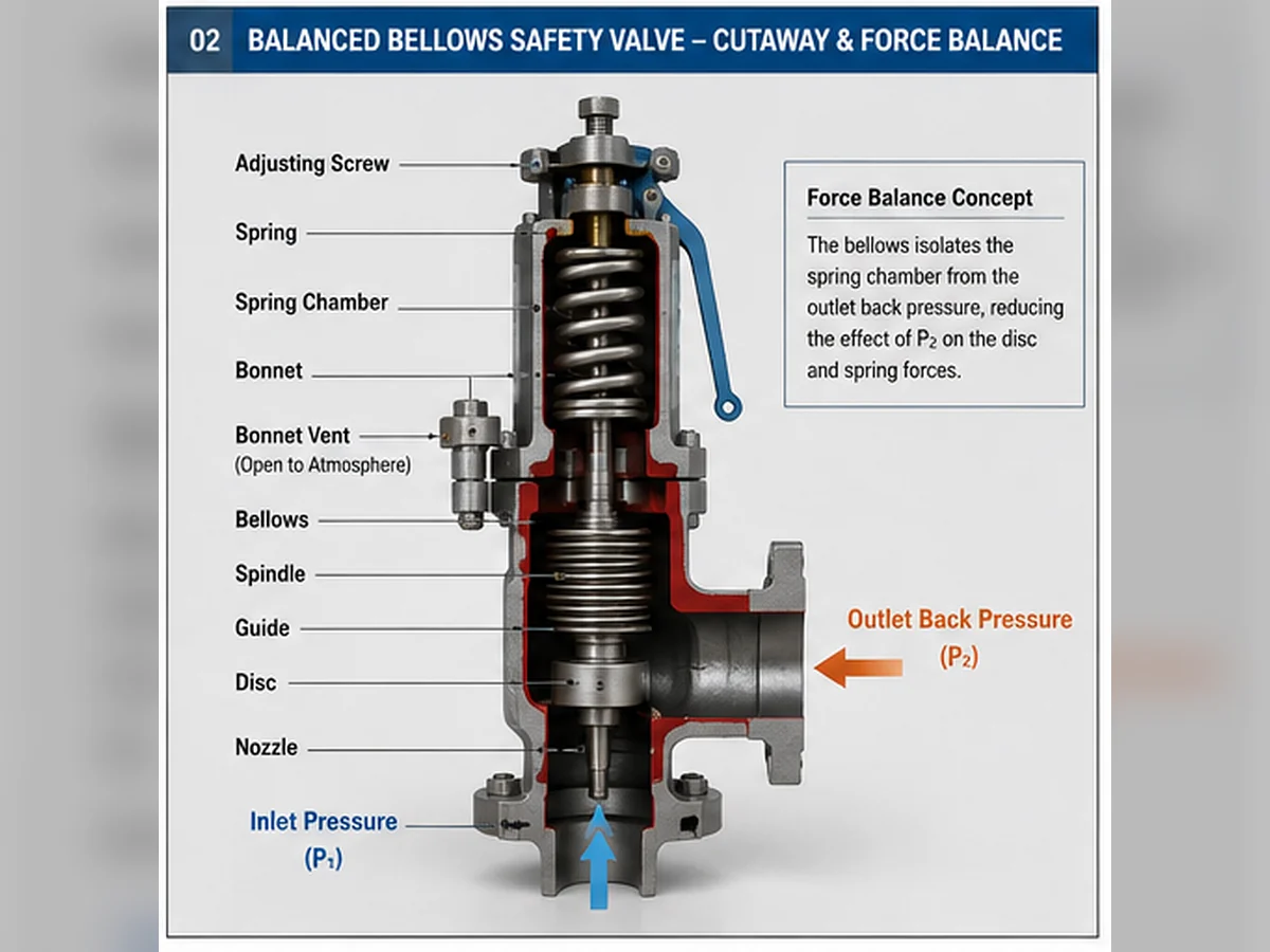
In a conventional spring-loaded valve, outlet pressure can act on internal areas around the disc holder, guide and bonnet-side assembly. Depending on the construction, this changes the net force opposing or assisting lift. A balanced bellows assembly uses a defined effective area to reduce part of that outlet-pressure force.
The design does not make the valve independent of the discharge system. Outlet pressure can still affect rated capacity, stability, blowdown, mechanical loading and the bellows itself. For a deeper explanation of superimposed and built-up pressure, use the dedicated back pressure and bellows engineering guide.
What it can help control
- Selected outlet-pressure forces on the moving assembly
- Spring-chamber exposure to some discharge media
- Back-pressure effects within manufacturer-defined limits
What it does not prove
- Adequate relieving capacity
- Acceptable outlet-header resistance
- Suitable bellows material and fatigue life
- Correct bonnet vent routing
Start with the Governing Relief Scenario
The valve configuration should not be selected before the required protection duty is defined. Identify the protected vessel, boiler, heat exchanger, compressor, pipeline, reactor, tank or skid and determine which credible case governs the required flow. Typical cases include blocked outlet, external fire, regulator failure, control-valve failure, tube rupture and thermal expansion.
The project should document operating pressure, MAWP or the applicable design-pressure limit, proposed set pressure, permitted overpressure or accumulation basis, medium and phase, required relieving rate, relieving temperature, expected inlet loss and outlet back pressure. The API 521 pressure-relief systems guide explains why valve selection must remain connected to relief-scenario and downstream-system review.
Engineering boundary: Set pressure is an opening reference. It is not the required relieving capacity, selected effective orifice or proof that the discharge system is acceptable.
Confirm Required Capacity Before Reviewing Valve Size
Connection size only describes the physical inlet and outlet interface. It does not establish the effective orifice or the valve’s certified or documented capacity. Two valves with the same nominal flanges can have different lift characteristics, coefficients, effective areas and rated flows.
Separate the required relieving load from the selected valve data. Steam, gas, liquid and two-phase cases cannot be interchanged without the applicable calculation method and properties. Process debottlenecking, changed fluid composition, a larger fire case or a modified header can invalidate a previous selection even when the set pressure and flange sizes remain unchanged. See the ZOBAI guide to safety valve sizing and certified relieving capacity.
| Selection item | Required project input | Approval evidence |
|---|---|---|
| Governing relieving load | Flow rate and calculation basis | Relief calculation |
| Fluid basis | Steam, gas, liquid or two-phase | Process data and method |
| Relieving conditions | Pressure and temperature | Calculation and datasheet |
| Selected effective orifice | Manufacturer designation and area | Certified or documented data |
| Rated capacity | Capacity at stated fluid and conditions | Manufacturer/certification data |
| Connections | Size, class/PN and facing/thread | GA drawing and piping review |
Define the Complete Back-Pressure Profile
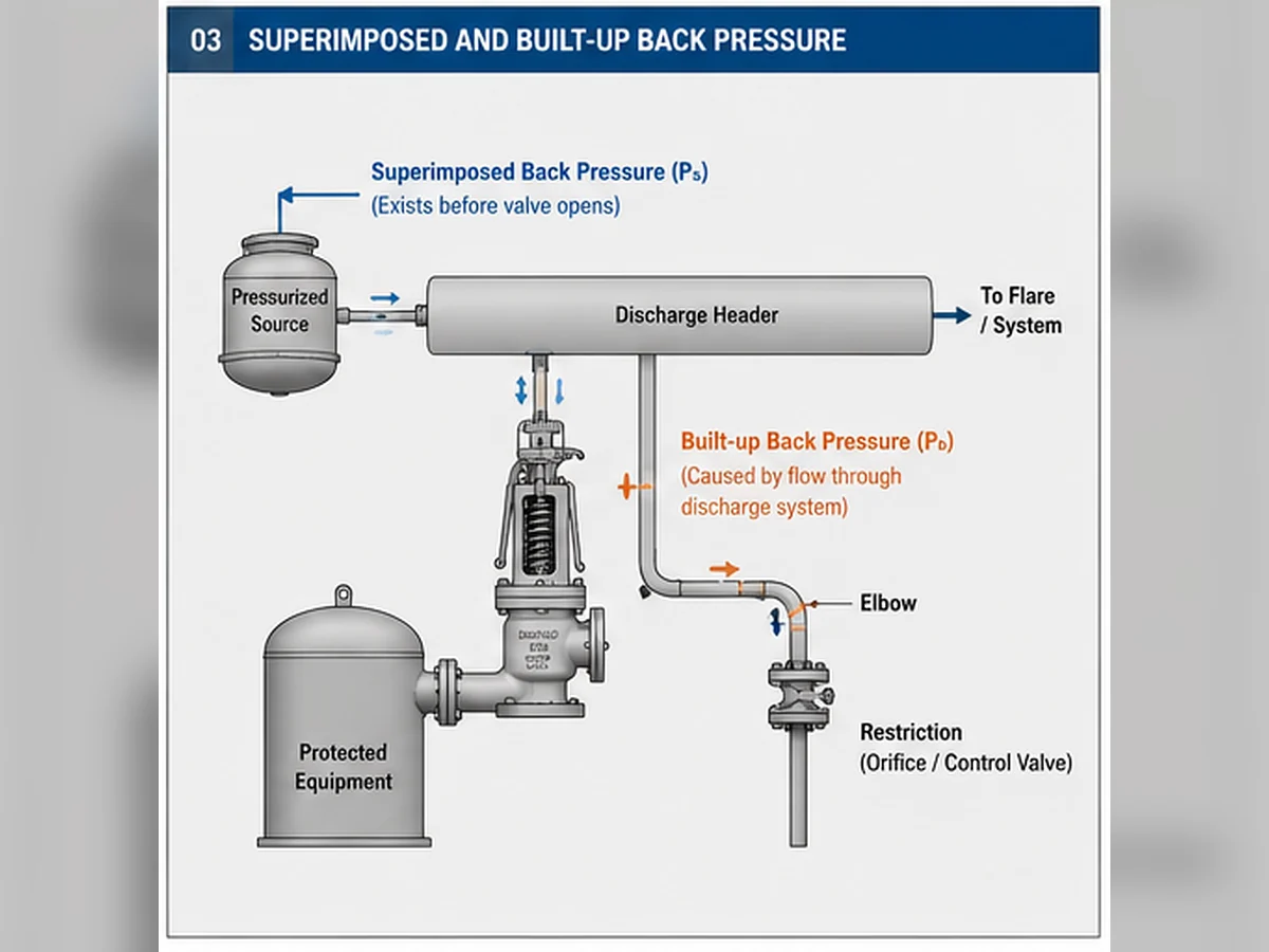
Do not submit one unexplained maximum outlet-pressure value. Distinguish the pressure present before opening from the pressure created by relief flow.
Superimposed back pressure
Pressure at the outlet before the valve opens. It may be constant or variable and can come from a continuously pressurized header, flare system or another connected source.
Built-up back pressure
Pressure produced after opening because relieving flow encounters resistance in the outlet pipe, fittings, common header and downstream equipment.
| Parameter | What to provide | Why it changes selection |
|---|---|---|
| Superimposed pressure | Minimum, normal and maximum; constant or variable | Changes the outlet pressure acting before lift |
| Built-up pressure | Calculated at the governing relieving flow | Can affect lift, capacity, stability and blowdown |
| Total back pressure | Applicable combination during relief | Must remain within model-specific limits |
| Header interaction | Simultaneous relief and operating cases | Can increase outlet pressure beyond single-valve estimates |
Compare the Back Pressure with the Selected Valve and Bellows Limits
There is no universal allowable back-pressure percentage for every balanced bellows design. The limit can depend on the model, set pressure, spring range, effective bellows area, fluid, capacity basis, bellows rating and required blowdown. Manufacturer-specific data must confirm whether a capacity correction applies and whether certified performance remains valid.
The bellows is a thin, flexible mechanical component. Review maximum differential pressure, relieving temperature, corrosion exposure, cyclic movement, vibration and fatigue. Loss of bellows integrity can remove the intended balancing function and may allow process fluid to enter the bonnet area or discharge from the vent.
Composite engineering scenario: common-header modification
A plant adds relief devices to an existing closed header. The original valve’s set pressure and flange sizes remain unchanged, but simultaneous relief increases built-up back pressure. The existing selection must be rechecked for capacity, stability, bellows limits and outlet load. Replacing the valve by nameplate size alone would not close the engineering gap.
Check the Medium and Every Relevant Material
A corrosion-resistant body does not prove that the complete valve is suitable. Review the nozzle, disc, disc holder, guide, spindle, spring, bellows, gasket and any soft seat or O-ring. The governing risks may include corrosion, stress-corrosion cracking, erosion, deposits, polymerization, galling, sticking, seal degradation and loss of spring stability.
Soft-seat and metal-seat choices must be checked against pressure, temperature, chemical compatibility and the project’s seat-tightness requirement. Sour-service and specific ASTM material requirements should only be invoked when the actual service and adopted specification make them applicable.
Composite engineering scenario: body material upgraded, bellows overlooked
A replacement valve is ordered with a more corrosion-resistant body, but the bellows and guide remain unspecified. If those components are exposed to the damaging medium, the valve can still lose movement, tightness or balancing function. The RFQ should therefore define the material requirement by component, not only by body grade.
Confirm the Bonnet Vent and Failure-Detection Arrangement
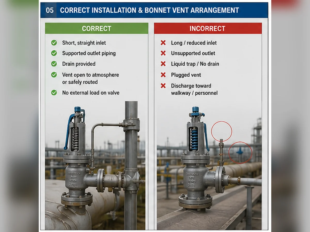
The bonnet vent is part of the functional design. It should not be plugged merely because vapor or liquid is observed. Discharge from the vent may indicate bellows leakage and should trigger an approved inspection response.
Review toxicity, flammability, corrosion, weather exposure, icing, condensate, vent-pipe resistance and a safe termination point. Any routed vent system must preserve the pressure reference intended by the manufacturer.
Do not treat a plugged vent as a repair. The correct action is to identify the source, inspect the bellows and restore the approved vent arrangement.
Review Inlet and Outlet Piping Before Final Selection
A valve can be correctly sized yet perform poorly in an unsuitable installation. The inlet should be reviewed for pressure loss, cleanliness, reducers, fittings, isolation arrangements and mechanical load. The outlet should be checked for resistance, support, thermal movement, reaction force, drainage, liquid pockets and safe discharge.
Use the safety valve installation guide to translate these conditions into the installation review. Chatter should not be attributed only to valve adjustment; oversizing, insufficient sustainable flow, excessive inlet loss, outlet back pressure and piping load can all contribute.
Decide Between Conventional, Bellows Balanced and Pilot-Operated Designs
A conventional spring-loaded valve may remain appropriate when verified back pressure is low or stable and within the selected model’s limits. A balanced bellows construction may reduce selected outlet-pressure effects but introduces bellows and vent considerations. A pilot-operated design may suit some operating-margin, capacity or back-pressure conditions, but pilot passages and sensing lines create their own contamination, condensation and freezing risks.
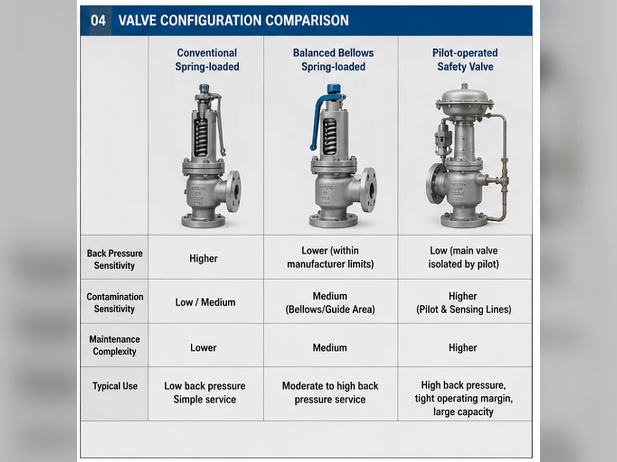
| Selection condition | Conventional spring-loaded | Balanced bellows | Pilot-operated |
|---|---|---|---|
| Low, stable back pressure | May be suitable | May be unnecessary | May be unnecessary |
| Back pressure affects force balance | Requires model review | Often considered | May also be considered |
| Dirty/polymerizing service | Guide and seat risk | Guide and bellows risk | Pilot/sensing-line risk |
| Condensing/freezing service | Bonnet/outlet review | Vent and bellows review | Pilot and sensing review |
| Maintenance complexity | Generally lower | Additional bellows inspection | Additional pilot components |
Verify Testing, Capacity Evidence and Documentation
Request documents that match the actual valve model and configuration: approved datasheet, GA drawing, effective orifice, rated or certified capacity, set-pressure basis, allowable back pressure, bellows material, body and trim materials, set-pressure test, seat-tightness test, nameplate data and installation/maintenance instructions.
Seat-tightness testing and capacity evidence serve different purposes. Passing a leakage test does not prove adequate relieving capacity. ZOBAI maintains separate practical guides for API 520 sizing and selection, API 526 flanged safety valves and the API 527 seat-tightness test.
Official reference boundaries
- API 520 Part I, 10th Edition addresses sizing and selection of pressure-relieving devices.
- API 520 Part II, 7th Edition addresses pressure-relieving-device installation and related engineering analysis.
- API Standard 521, 7th Edition addresses pressure-relieving and depressuring systems, including relief scenarios and disposal-system design.
- ISO 4126-1:2013 remains current after confirmation in 2025 and is a safety-valve product standard rather than an application standard.
- The National Board Inspection Code governs in-service pressure-equipment installation, inspection, repair and alteration and supports the VR accreditation route; it does not replace valve sizing or installed-system review.
These references were checked against official sources on July 18, 2026. The project must still verify the editions adopted by the purchaser, jurisdiction and equipment code before approval.
Common Bellows Balanced Safety Valve Selection Mistakes
- Selecting from inlet and outlet size alone.
- Providing only one back-pressure value without separating superimposed and built-up components.
- Assuming “balanced” means unaffected by back pressure.
- Ignoring bellows pressure, temperature, corrosion and fatigue limits.
- Specifying body material while leaving the bellows, nozzle, disc and guide undefined.
- Plugging or misrouting the bonnet vent.
- Failing to recheck the valve after a common-header modification.
- Treating a successful set-pressure test as capacity proof.
- Replacing an old valve by appearance or flange size alone.
- Ignoring outlet support, drainage and reaction force.
Bellows Balanced Safety Valve RFQ Checklist
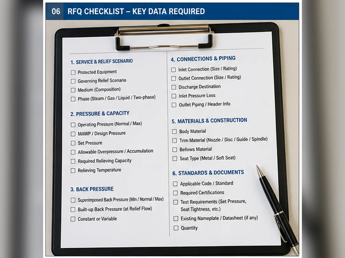
| RFQ field | Information to provide |
|---|---|
| Protected equipment | Vessel, boiler, exchanger, pipeline, compressor, skid or other equipment |
| Governing relief scenario | Blocked outlet, fire, regulator failure, tube rupture, thermal expansion or other case |
| Medium and phase | Composition; steam, gas, vapor, liquid or two-phase |
| Pressure basis | Operating pressure, MAWP/design pressure, set pressure and overpressure/accumulation basis |
| Required capacity | Relieving rate, calculation basis, relieving pressure and temperature |
| Back pressure | Superimposed minimum/normal/maximum; built-up at governing flow; constant or variable |
| Connections and piping | Inlet/outlet size, rating, facing/thread, discharge destination and header information |
| Materials | Body, nozzle, disc, guide, spindle, bellows, spring, gasket and seat/seal |
| Standards and documents | Adopted code, capacity evidence, material records, drawings, tests and witness requirements |
| Replacement information | Existing nameplate, photos, datasheet, GA and service history |
Frequently Asked Questions
When should a bellows balanced safety valve be selected?
Review it when verified outlet back pressure could materially affect a conventional valve’s force balance, opening stability, capacity or blowdown. Final selection still requires the complete relief-case and discharge-system data.
Does a balanced bellows eliminate back-pressure effects?
No. It can reduce selected pressure-force effects, but total back-pressure limits, capacity corrections, outlet resistance, stability and bellows limits may still apply.
What is the difference between superimposed and built-up back pressure?
Superimposed back pressure exists before the valve opens. Built-up back pressure develops after opening because relieving flow encounters resistance in the outlet and downstream system.
Can connection size determine relieving capacity?
No. Capacity depends on the required relieving load, effective orifice, valve design, fluid, relieving pressure, temperature and certified or documented performance.
What happens if the bellows fails?
The intended balancing function may be lost, and process fluid may enter the bonnet area or discharge through the vent. The exact consequence depends on the valve construction and service.
Should the bonnet vent be plugged?
Not without explicit manufacturer and engineering approval. Vent discharge can indicate bellows leakage, and plugging the vent can alter the intended pressure arrangement.
How should the bellows material be selected?
Use the actual medium composition, relieving temperature, differential pressure, corrosion mechanisms, expected cycles and manufacturer-specific data. Do not infer it solely from the body material.
When should a pilot-operated valve be considered?
It may be reviewed for some back-pressure, operating-margin or large-capacity services, but pilot passages and sensing lines introduce their own contamination, condensation, freezing and maintenance limits.
Request an Engineering Review
Send the protected equipment, governing relief scenario, medium and phase, operating pressure, MAWP or design pressure, set pressure, required relieving capacity, relieving temperature, superimposed and built-up back pressure, inlet/outlet connections, materials, adopted code and required documents.








Comments
Kesari Alloys
The emphasis on defining the complete back-pressure profile before selecting a bellows balanced safety valve is crucial. It’s interesting to note that the article mentions how outlet pressure can still affect stability and capacity, which highlights the need for thorough analysis. Have you encountered specific cases where the back-pressure profile significantly altered the valve performance or necessitated a redesign? Understanding those scenarios could benefit many engineers in the field.