Share your medium, set pressure, temperature, size, standard, or datasheet, and our team will review your requirement and respond with the appropriate next step.
A safety valve works by remaining closed during normal operation, opening automatically when pressure reaches its defined set pressure, discharging enough fluid to limit the pressure rise, and reseating after system pressure falls through the valve’s blowdown range. That sequence sounds simple, but real safety valve performance depends on the complete pressure-relief system. Spring force, nozzle …
A safety valve works by remaining closed during normal operation, opening automatically when pressure reaches its defined set pressure, discharging enough fluid to limit the pressure rise, and reseating after system pressure falls through the valve’s blowdown range. That sequence sounds simple, but real safety valve performance depends on the complete pressure-relief system. Spring force, nozzle area, disc geometry, fluid phase, required relieving capacity, inlet pressure loss, outlet back pressure, material condition, seat tightness, piping support, and maintenance quality all influence how the valve opens, reaches lift, relieves, and closes.
This explains why a safety valve can pass a workshop set-pressure test and still chatter, simmer, leak, fail to reach stable lift, or reseat poorly after installation. A bench test confirms specific valve characteristics under controlled conditions. It does not reproduce every field variable, such as compressor pulsation, wet steam, flashing liquid, a restrictive inlet branch, a common discharge header, thermal distortion, pipe strain, dirty media, or a changed flare-system pressure.
Users often ask why a safety valve opens suddenly instead of gradually.
Many buyers want to know why a valve that passed testing can still leak or chatter after installation.
Engineers need to distinguish set pressure testing, seat tightness testing, and certified relieving capacity because they prove different aspects of performance.
The answers usually come from the relationship between spring force, fluid force, pop action, required flow, blowdown, back pressure, and installed piping.
Terminology also matters. A traditional safety valve is commonly associated with rapid opening in steam, gas, or vapor service. A relief valve is commonly associated with proportional opening in liquid service. A safety relief valve may serve compressible or incompressible fluids depending on its design and certification. PSV is frequently used as a general plant term, but the datasheet must still define the actual valve type, medium, sizing basis, set pressure, capacity, and applicable standard. See PRV vs PSV vs safety valve vs relief valve for a detailed terminology comparison.
What a Safety Valve Does Before It Opens
Normal Closed Position and the Balance Between Spring Force and System Pressure
A direct spring-loaded safety valve remains closed because the downward spring force and seating force are greater than the upward pressure force acting on the disc during normal operation. The spring transmits its load through the spindle or stem to the disc. The disc contacts the nozzle seat and prevents process fluid from entering the discharge passage. As system pressure rises, the upward force acting on the effective disc area also rises. The valve remains closed until the pressure-force relationship reaches the specified opening condition.
The simplified force concept is useful, but the actual valve is not governed by spring compression alone. Disc geometry, nozzle geometry, huddling chamber, adjusting rings where fitted, friction, temperature, back pressure, and the fluid’s compressibility all influence the response. This is why two safety valves with similar connection sizes can have different opening behavior, blowdown, lift, and certified capacity.
From an operating perspective, a safety valve is not intended to function as a control valve. It should not continuously throttle routine process fluctuations. It should remain tight during normal service, respond to a defined overpressure event, relieve the required load, and close after pressure has returned to the acceptable range.
Engineering boundary: A safety valve that repeatedly simmers or lifts during normal process fluctuations is usually indicating an operating-margin, pressure-control, sizing, seat-condition, or installation problem. Repeated operation should not be treated as normal control duty.
Set Pressure, Operating Pressure, and Why the Margin Matters
Normal operating pressure must remain sufficiently below the valve’s opening region to support stable shutoff and acceptable seat life. Set pressure is the pressure at which the valve is adjusted to begin its specified opening response under defined test conditions. Operating pressure is the pressure the valve normally sees in service. The difference between them is commonly discussed as operating margin.
There is no single operating-margin percentage that is correct for every safety valve. The appropriate margin depends on valve design, seat type, process stability, pressure pulsation, fluid cleanliness, temperature, back pressure, blowdown, leakage requirement, manufacturer guidance, and the governing code or owner specification. A clean, stable gas system may tolerate a different margin from wet steam, reciprocating-compressor discharge, dirty hydrocarbon service, or a reactor with rapid pressure cycling.
Table: What These Pressure Terms Mean in Practice
Term
Engineering Meaning
What It Affects
Operating Pressure
The pressure experienced during normal service.
Seat loading, simmer risk, leakage, and cycling frequency.
Set Pressure
The pressure at which the valve is adjusted to begin its specified opening response.
When overpressure protection starts.
Operating Margin
The separation between operating pressure and the valve’s opening region.
Shutoff stability, simmer, seat wear, and leakage risk.
MAWP
The maximum allowable working pressure of the protected equipment under the applicable code basis.
The allowable pressure boundary used when establishing the relief arrangement.
Relieving Pressure
The pressure used for capacity calculation during the relieving event.
Available driving pressure and required orifice area.
Set pressure should be established against the protected equipment’s allowable pressure limit and the applicable boiler, pressure-vessel, piping, or local regulatory requirements. A universal rule allowing set pressure to exceed MAWP should not be applied. Multiple-device arrangements, supplemental devices, fire cases, boilers, and pressure vessels can have different requirements.
Composite engineering scenario: A gas receiver safety valve repeatedly developed seat leakage even though each workshop test was acceptable. The receiver normally operated very close to set pressure, and compressor pulsation caused frequent pressure peaks. The seat was being damaged by repeated simmer rather than by a single manufacturing defect. The corrective action was to review the operating envelope, pressure-control stability, seat configuration, and set-pressure arrangement instead of repeatedly lapping the seat.
What Users Often Misunderstand About “Opening Pressure” in Real Systems
Bench set pressure is an essential valve setting, but it does not prove that the complete installed system will open and relieve stably. The pressure measured at the protected vessel, the pressure at the valve inlet, and the pressure acting across the moving assembly may differ during relieving flow. Inlet pressure loss can reduce the pressure available at the nozzle after the valve begins to open. Outlet back pressure can change the force balance, effective capacity, blowdown, and reseating response.
Temperature can also matter. Spring characteristics, material clearances, soft-seat behavior, gasket condition, and process-fluid properties may differ between ambient shop testing and hot or cryogenic service. Manufacturer procedures may therefore require temperature corrections or service-specific test considerations.
Another common misunderstanding is assuming that the valve’s connection size proves its protective capacity. Connection size shows how the valve attaches to the system. Required relieving capacity comes from the governing overpressure scenario, while certified or project-accepted capacity comes from the selected valve, effective orifice, coefficients, set pressure, fluid, and applicable test basis. See why certified relieving capacity is more important than connection size.
How a Safety Valve Works Step by Step
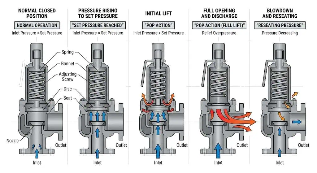
A direct spring-loaded safety valve moves through closed, initial-lift, rapid-opening, relieving, blowdown, and reseating stages. Actual behavior depends on the valve design and installed system.
Pressure Builds Up Until the Set Point Is Reached
The operating sequence begins as pressure increases in the protected equipment while the valve remains seated. As pressure rises, the upward fluid force beneath the disc increases. The spring continues to hold the disc against the nozzle until the specified opening condition is reached. Before this point, a correctly selected and maintained valve should remain acceptably tight for its design and test standard.
The rate of pressure rise matters. A slowly developing blocked-outlet case and a rapid gas blowby or runaway reaction do not impose the same dynamic demand. The safety valve still responds to pressure, but the required capacity, accumulation, valve lift, and downstream disposal system must be capable of managing the governing event.
This is why sizing begins with the overpressure scenario rather than the valve catalogue. The process determines the relief demand. The valve is then selected to satisfy that demand within the applicable pressure boundary.
Initial Lift, Rapid Opening, and Why Pop Action Happens
When a compressible-fluid safety valve begins to lift, the escaping steam, gas, or vapor can generate additional opening force that drives the disc rapidly toward a larger lift. The initial opening exposes additional disc or huddling-chamber area to pressure and flowing-fluid forces. Depending on valve design, these forces increase more rapidly than the spring closing force, producing the characteristic pop action associated with many steam and gas safety valves.
Pop action is not simply a dramatic noise. It allows the valve to move quickly away from a small throttling position and establish a larger flow area. Prolonged operation at very small lift can erode seating surfaces, create unstable force balance, and increase chatter risk.
A liquid relief valve may open more proportionally because liquid is comparatively incompressible and the required response may differ. A safety relief valve can be designed for gas, vapor, steam, or liquid duty, but the exact opening characteristic must match the service and certification basis.
Terminology note: Rapid pop action is commonly associated with compressible-fluid safety valves. Proportional lift is more commonly associated with liquid relief valves. The actual device datasheet and certification should control the terminology used for procurement.
Pressure Relief, Full Lift Region, and Flow Discharge
After opening, the valve must pass enough flow to keep the protected system within its permitted pressure boundary during the governing event. Opening alone does not prove adequate protection. If the required inflow or pressure-generation rate is greater than the valve’s effective relieving capacity, system pressure can continue to rise even while the valve is open.
Required relieving capacity is calculated from the credible overpressure scenario, such as blocked outlet, external fire, control-valve failure, tube rupture, gas blowby, thermal expansion, utility failure, or runaway reaction. The selected valve must then provide sufficient certified or project-accepted capacity at the specified relieving pressure, temperature, fluid state, and back pressure.
Table: What Controls the Real Relieving Phase
Factor
Why It Matters
Failure Risk
Required Relieving Capacity
Defines the minimum flow needed to protect the equipment.
Pressure continues rising even though the valve is open.
Effective / Certified Orifice Area
Controls the rated flow area used by the selected valve.
A same-size valve may have insufficient capacity.
Fluid Type and Properties
Gas, steam, liquid, flashing liquid, and two-phase flow require different sizing treatment.
Incorrect required area or unstable discharge.
Relieving Pressure and Temperature
Determine density, available pressure differential, material condition, and mass flow.
Incorrect capacity or unsuitable materials.
Outlet Back Pressure
Can change force balance, effective capacity, blowdown, and reseating.
Reduced flow, unstable lift, or leakage after relief.
Inlet Pressure Loss
Changes the pressure available at the nozzle during flow.
Chatter, flutter, reduced lift, and seat damage.
An oversized valve is not automatically safer. If the selected orifice is much larger than the actual relieving demand, the process may not sustain stable lift. The valve can open rapidly, reduce local pressure, close, and reopen repeatedly. Correct selection normally seeks an approved valve and orifice that safely satisfy the required capacity without unnecessary oversizing.
Composite engineering scenario: A replacement valve had the same inlet and outlet sizes and the same set pressure as the original valve. During document review, engineers found that its certified capacity was lower because its effective orifice and coefficient basis differed. The valve would physically fit, but it could not satisfy the current blocked-outlet load. The prevention was to compare required relieving capacity and certified capacity rather than approving the replacement from dimensions alone.
Blowdown, Reseating, and How the Valve Closes Again
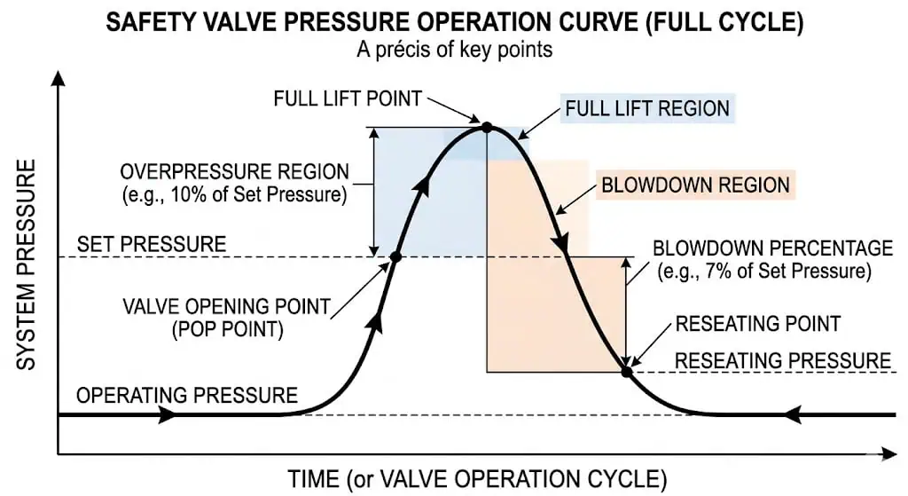
The valve normally reseats below set pressure. Blowdown provides separation between opening and closing so the valve can recover without rapid cycling.
A safety valve normally closes at a pressure below its set pressure. The difference between the set pressure and reseating pressure is called blowdown. Blowdown allows the process pressure to recover below the opening region before the disc returns firmly to the seat. Without sufficient separation, the valve may close and reopen rapidly as pressure fluctuates around the set point.
Blowdown is influenced by valve design, adjusting-ring position where applicable, spring force, disc and nozzle geometry, fluid compressibility, inlet pressure loss, and back pressure. It should not be adjusted casually in the field. An incorrect adjustment can produce excessive product loss, delayed closure, cycling, chatter, or seat damage.
Table: Terms Users Should Not Mix Up
Term
Meaning
Engineering Effect
Set Pressure
The pressure at which the valve is adjusted to begin its specified opening response.
Controls when protection begins.
Overpressure
The pressure increase above set pressure while the valve is relieving.
Provides the pressure required to develop relieving capacity.
Accumulation
The pressure increase above the protected equipment’s MAWP or allowable boundary during the event.
Determines whether the equipment remains within the code-permitted temporary pressure range.
Blowdown
The difference between set pressure and reseating pressure.
Controls the closing interval and process recovery.
Reseating Pressure
The pressure at which the disc re-establishes contact with the seat after relief.
Affects leakage, product loss, and repeated cycling.
Set pressure, overpressure, accumulation, and blowdown are related but not interchangeable. Their allowable values depend on the protected equipment, applicable code, valve design, number of relieving devices, and overpressure scenario. For more detail, see set pressure, overpressure, accumulation, and blowdown in safety valves.
Composite Field Scenario for Engineering Training: When the Valve Opened at the Right Pressure but Failed to Reseat Cleanly
A safety valve can open at the specified pressure and still fail to complete the relieving cycle correctly. In a composite maintenance case, a direct spring-loaded valve lifted at the expected pressure during a real process upset but continued leaking after system pressure returned to normal. Inspection found debris embedded in the seat, light scoring on the disc face, and guide misalignment caused by rough handling during the previous overhaul.
The visible symptom was seat leakage, but the root causes included inadequate maintenance cleanliness, poor component handling, incomplete alignment checks, and failure to investigate contamination in the inlet branch. The corrective action was to clean the inlet and internals, restore the seating surfaces, verify guide and spindle alignment, complete set-pressure and seat-tightness tests, document the repair, and reseal the adjustment before reinstallation.
This example shows why a post-lift leak should not automatically be classified as “normal valve wear.” The maintenance process, process medium, piping cleanliness, operating margin, and outlet conditions all need review.
The Main Components That Make a Safety Valve Work
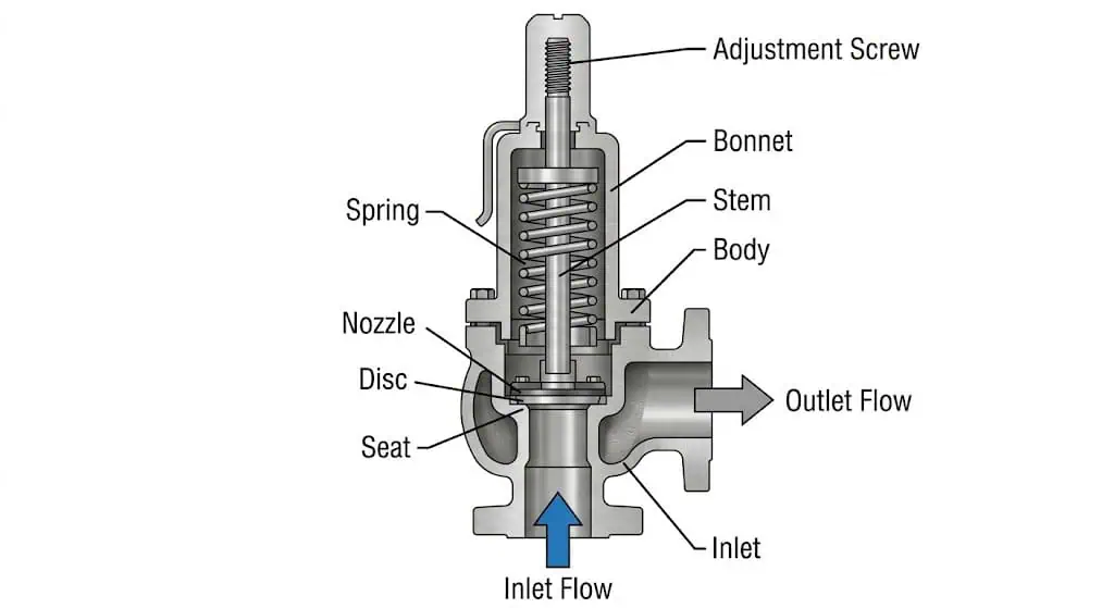
The body, nozzle, disc, guide, spindle, spring, adjustment system, and sealing surfaces work together. Failure of one component can change opening, capacity, stability, or reseating.
Body, Nozzle, and Flow Path
The body contains the pressure-retaining and discharge passages, while the nozzle provides the primary pressure-sensing area, seating surface, and entrance to the relieving flow path. The body must satisfy the required pressure-temperature rating, material standard, external environment, and connection requirements. The nozzle must resist corrosion, erosion, galling, thermal distortion, and repeated seat impact.
Deposits or damage in the nozzle and flow path can reduce lift, change effective flow area, prevent tight closure, or create asymmetric forces on the disc. In dirty or polymerizing service, even a correctly sized valve can become unreliable if the inlet passage or nozzle becomes restricted.
The internal flow path also affects discharge reaction, pressure recovery, noise, and interaction with the outlet system. The valve body and outlet connection should therefore be evaluated together with the discharge piping rather than as separate items.
Spring, Stem, and Adjustment Screw
The spring supplies the calibrated closing force, the spindle or stem transmits that force, and the adjustment screw changes the spring compression used to establish set pressure. Spring material, operating temperature, corrosion, relaxation, fatigue, coating condition, and manufacturing range all affect long-term stability.
The spindle and guide must remain aligned and move freely. Corrosion, deposits, galling, bent components, improper assembly, side loading, or non-approved installation orientation can add friction and change both opening and reseating behavior.
Table: Why These Parts Matter to Buyers
Component
Function
What Buyers Should Confirm
Spring
Provides closing force and determines the calibrated set-pressure range.
Material, temperature range, corrosion protection, approved spring range, and traceability.
Stem / Spindle
Transfers spring force to the disc assembly.
Alignment, straightness, surface condition, and compatibility with guides.
Guide
Controls movement of the disc holder and spindle.
Clearance, anti-galling material pairing, fouling risk, and wear.
Adjustment Screw
Changes spring compression for set-pressure calibration.
Controlled adjustment, locking, sealing, and repair records.
Bonnet
Contains or protects spring and adjustment components.
Open, closed, or gas-tight construction; venting; temperature; and process exposure.
After adjustment, the setting should be tested and secured in accordance with the applicable quality system, owner procedure, and regulatory requirements. An unsealed or undocumented adjustment creates uncertainty about the actual set pressure and repair history.
Disc and Seat Contact Surfaces
The disc and nozzle seat form the primary sealing interface and strongly influence normal-service leakage, opening repeatability, and post-relief reseating. Metal seats tolerate high temperature and many severe services but require accurate surface condition and alignment. Soft seats may improve tightness in suitable clean services but are limited by temperature, chemical compatibility, ageing, decompression damage, fire exposure, and contamination.
Scoring, pitting, wire drawing, corrosion, embedded debris, uneven lapping, thermal distortion, or off-centre contact can create leakage. Repeated chatter can damage both surfaces in a short period because the disc repeatedly impacts the nozzle.
Seat tightness is not the same as certified relieving capacity. A valve may pass a leakage test but still be incorrectly sized, and a valve with adequate capacity may still leak because of damaged seating surfaces. API 527 or another project-accepted method may be specified to evaluate seat tightness for applicable pressure relief valves.
Why Wear, Corrosion, or Dirt in These Parts Changes Real Valve Behavior
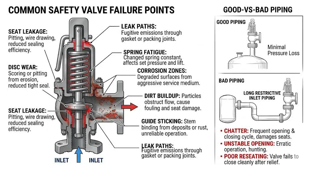
Internal parts do not deteriorate uniformly, so an apparently sound valve body does not prove that the moving and sealing components remain fit for service. Nozzle corrosion changes the seating profile. Guide deposits add friction. Spring corrosion changes force and reliability. Disc erosion changes flow and sealing. Bellows damage can expose the spring chamber to process fluid or alter the valve’s response to back pressure.
Damage Mechanism
Typical Component
Possible Operating Effect
Corrosion or pitting
Nozzle, disc, guide, spindle, spring, bellows.
Leakage, sticking, reduced strength, or altered set-pressure response.
Erosion / wire drawing
Seat and nozzle flow edge.
Persistent leakage and loss of sealing geometry.
Deposits or polymerization
Inlet, guide, disc holder, pilot passages.
Restricted lift, delayed opening, or failure to reseat.
Spring relaxation or fatigue
Spring.
Set-pressure drift or reduced closing force.
Galling or misalignment
Spindle and guide.
Friction, unstable lift, sticking, or uneven seat contact.
Soft-seat ageing or swelling
O-rings and resilient seats.
Leakage, extrusion, sticking, or material breakdown.
Material compatibility must therefore cover the body, bonnet, nozzle, disc, guide, spindle, spring environment, bellows, gaskets, and soft parts. For component-level selection, see the safety valve material selection guide.
Why Some Safety Valves Do Not Work as Expected
Safety valve failures often result from an interaction between internal condition and installed system effects rather than one isolated component defect.
Why a Safety Valve Leaks After Opening or During Normal Operation
Safety valve leakage can result from seat contamination, damaged sealing surfaces, component misalignment, unsuitable operating margin, vibration, thermal distortion, corrosion, back pressure, or poor repair control. The visible leak is a symptom. Effective troubleshooting determines whether the root cause is inside the valve, in the process, in the piping, or in the previous maintenance work.
Table: Leakage Problem Review
Observed Problem
Likely Technical Causes
Corrective Direction
Leakage after lift
Debris, seat-face damage, erosion, disc misalignment, or poor reseating.
Inspect and clean the seat, disc, nozzle, guide, inlet branch, and outlet conditions.
Review process pressure, seat condition, spring condition, temperature, and valve selection.
Intermittent leakage
Vibration, pipe strain, variable back pressure, unstable process pressure, or guide friction.
Review piping support, alignment, discharge header, and operating history.
Leakage soon after repair
Incorrect lapping, wrong components, contamination, poor calibration, or installation damage.
Audit repair records, component traceability, test results, handling, and reinstatement.
Repeated leakage in corrosive service
Unsuitable nozzle, disc, guide, bellows, gasket, or soft-seat material.
Reassess complete material compatibility rather than body material alone.
Operating too close to set pressure is a frequent cause of recurring leakage. The disc may experience simmer or micro-lift, allowing high-velocity fluid to damage the seat before a full relief event occurs. Increasing spring compression without checking the protected-equipment limit is not an acceptable correction.
Why Chatter, Flutter, or Simmer Happens Before Stable Relief
Simmer, flutter, and chatter describe different unstable behaviours, but all indicate that the valve and system are not moving through the opening sequence cleanly. Simmer is small leakage or visible flow immediately before full opening. Flutter is rapid low-amplitude movement of the moving assembly. Chatter is repeated high-amplitude contact between the disc and seat.
Typical causes include:
Excessive inlet pressure loss after the valve begins to flow.
Built-up or variable back pressure in the discharge system.
An oversized valve whose lift cannot be sustained by the actual relief load.
Operating pressure too close to set pressure.
Incorrect blowdown adjustment or damaged internal geometry.
Two-phase, flashing, pulsating, or acoustically unstable flow.
Guide friction, deposits, corrosion, misalignment, or spring problems.
Chatter can quickly damage the nozzle, disc, spindle, guide, and piping because the moving parts repeatedly accelerate and impact. It should not be treated as an acceptable feature of relief operation.
How Back Pressure, Inlet Loss, and Outlet Routing Affect the Working Sequence
Inlet pressure loss and outlet back pressure alter the pressure forces available during opening, full lift, and reseating. A restrictive inlet branch can cause the pressure at the valve nozzle to drop after opening, even while pressure remains high in the protected equipment. The valve may then begin to close, allowing pressure to rebuild and producing chatter.
Superimposed back pressure exists at the outlet before the valve opens. Built-up back pressure develops after flow enters the discharge piping. Depending on valve design, these pressures can affect set-pressure behaviour, lift, effective capacity, blowdown, and reseating. See superimposed vs built-up back pressure.
Table: Piping Effects Users Commonly Miss
Piping Issue
What It Can Cause
Required Review
Long or restrictive inlet
Pressure collapse at the nozzle, flutter, chatter, and reduced lift.
Relieving-flow pressure loss and dynamic stability.
Undersized or long outlet
Built-up back pressure, reduced effective performance, noise, and vibration.
Outlet hydraulic calculation and valve back-pressure limit.
Common discharge header
Variable superimposed back pressure and simultaneous-relief interaction.
Credible header loads and flare or vent-system conditions.
Poor pipe support
Reaction loads, misalignment, vibration, and body/nozzle stress.
Mechanical support, thermal movement, and reaction-force analysis.
Liquid pockets or blocked drains
Corrosion, freezing, additional back pressure, and water-hammer risk.
Drainage, low points, weather protection, and discharge routing.
API 520 Part II is relevant to installation review, including inlet and outlet considerations. Its current framework includes an engineering-analysis route for installations requiring more than a simple screening criterion. A familiar inlet-loss percentage should not be applied blindly to every valve, fluid, or dynamic system.
Composite Field Scenario for Engineering Training: A Spring Loaded Valve That Chattered Because the Inlet Line Was Too Restrictive
A compressor-discharge safety valve chattered repeatedly during upset conditions even though it had passed set-pressure and seat-tightness tests. The valve was initially blamed because the problem occurred only when it lifted. Field review showed that the inlet branch was longer and smaller than the approved design and included several fittings. Once relieving flow started, the pressure at the valve inlet dropped rapidly, causing the valve to close and reopen.
The correction was not a higher pressure class or a stronger spring. Engineers redesigned the inlet connection, reduced pressure loss, checked the selected orifice against the actual load, and reviewed the outlet back pressure. After the piping correction, the same valve design operated stably.
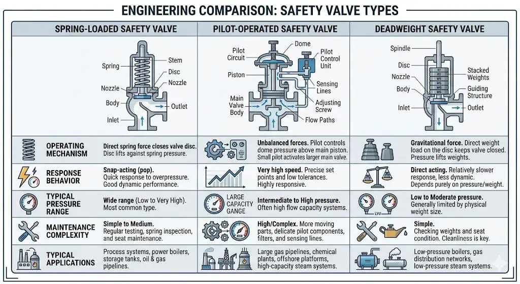
How Different Safety Valve Types Work
Valve types should be compared by operating principle, service cleanliness, back pressure, required tightness, capacity, temperature, and maintenance capability.
How a Spring-Loaded Safety Valve Works
A direct spring-loaded safety valve uses a calibrated spring as the primary closing-force element. System pressure acts directly beneath the disc. When the opening force reaches the valve’s set condition, the disc lifts and the valve relieves. As pressure falls through the blowdown range, the spring closes the disc against the nozzle.
Spring-loaded valves are mechanically straightforward and widely used in boilers, pressure vessels, utility systems, air, gas, vapor, steam, and applicable liquid services. Their performance can become sensitive to operating margin, inlet loss, outlet back pressure, guide friction, deposits, and spring temperature.
A conventional spring-loaded valve may be appropriate where back pressure is low and predictable. A balanced bellows safety valve may be reviewed where outlet pressure would otherwise disturb a conventional design, subject to bellows material, fatigue, pressure, temperature, and bonnet-vent requirements.
How a Pilot-Operated Safety Valve Works
A pilot-operated safety valve uses system pressure and a smaller pilot valve to control the opening and closing of the main valve. During normal operation, the pilot system maintains pressure in a control chamber so that the main valve stays closed. When set pressure is reached, the pilot changes the control pressure and allows the main valve to open.
Pilot-operated designs can provide tight shutoff and can be suitable where operating pressure is close to set pressure, where large capacity is required, or where certain back-pressure conditions make a conventional valve less suitable. They are not universally superior. Small pilot passages, sensing lines, filters, seals, and control components can plug, freeze, corrode, or become unstable in dirty, waxy, hydrate-prone, polymerizing, or condensable service.
Service cleanliness, pilot-line routing, drainage, heating, material compatibility, maintenance capability, and owner acceptance should be reviewed before selecting a pilot-operated safety valve.
How Deadweight Safety Valves Work and Where They Still Matter
A deadweight safety valve uses calibrated mass rather than a compression spring to provide the closing force. Weights act through the valve mechanism to hold the disc on the seat. When the pressure force exceeds the weight-derived closing force, the valve lifts.
Deadweight valves are mechanically understandable but are generally limited to specialised, legacy, laboratory, or lower-pressure applications. Orientation, vibration, movement of the equipment, and unauthorised changes to the weights can directly affect the setting. They are not normally the preferred solution for modern high-pressure process systems.
Expert View: Why Engineers Do Not Compare These Types by Structure Alone but by Service Conditions
The correct valve type is the design that remains stable, maintainable, adequately sized, and acceptable under the actual service conditions. No design is automatically best for all applications.
Selection Condition
Direct Spring-Loaded
Balanced Bellows
Pilot-Operated
Low and predictable back pressure
Often suitable within manufacturer limits.
May be unnecessary.
May be unnecessary unless another requirement applies.
Variable or significant back pressure
May become unsuitable.
Often reviewed to reduce back-pressure influence.
May be suitable depending on pilot design and service.
Operating pressure close to set pressure
Simmer and leakage may require attention.
Balancing alone does not guarantee tighter shutoff.
Can provide tight shutoff in suitable clean service.
Dirty or polymerizing medium
May be more tolerant depending on trim.
Guides and bellows still require contamination review.
Pilot passages may plug or become unstable.
Corrosive discharge
Bonnet and spring exposure must be checked.
Bellows material and bonnet venting are critical.
Pilot and sensing-system materials must be compatible.
Maintenance resources
Generally simpler.
Adds bellows inspection.
Adds pilot, filter, tubing, and control-system maintenance.
Composite engineering scenario: A pilot-operated valve was selected for a dirty hydrocarbon gas system because the operating pressure was close to set pressure. The main valve initially remained tight, but condensate and solids entered the pilot sensing system and caused unstable operation. The corrective action involved cleaning and redesigning the pilot arrangement, but the long-term review also considered whether a direct spring-loaded or balanced bellows valve would be more tolerant of the actual service.
What Changes the Way a Safety Valve Works in Real Applications
Steam, Gas, and Liquid Service Differences
Fluid phase changes the valve’s opening characteristic, sizing method, discharge behaviour, and failure risks. Steam and gas are compressible. Expansion during initial lift can help generate rapid pop action. Liquid is comparatively incompressible and is commonly handled by a relief valve with more proportional opening. Flashing liquids and two-phase mixtures require additional care because phase change can occur inside the inlet, nozzle, valve body, or outlet system.
Service
Typical Behaviour
Critical Review Points
Steam
Rapid opening, high temperature, large discharge reaction, possible condensate.
Boiler or pressure-vessel code route, materials, blowdown, drainage, outlet support, and noise.
Gas / Vapor
Compressible flow with rapid expansion and possible pop action.
Molecular weight, compressibility, temperature, back pressure, pulsation, and certified gas capacity.
Liquid
More proportional lift in suitable relief-valve designs.
Viscosity, density, thermal expansion, reaction forces, and liquid-certified capacity.
Approved calculation method, instability risk, separator behaviour, and discharge-system capacity.
A valve selected for clean gas service should not be copied directly into viscous liquid, wet steam, or flashing service merely because the connection and set pressure are similar.
High Temperature, Dirty Media, and Corrosive Service Effects
Severe service can change spring force, clearances, seat condition, material strength, guide friction, and the valve’s ability to complete the opening and closing cycle. High temperature may cause spring relaxation, oxidation, gasket deterioration, soft-seat damage, and thermal distortion. Cryogenic service can cause contraction, icing, and brittle-fracture concerns if materials are unsuitable.
Dirty media can deposit on the nozzle, disc, guide, or pilot passage. Corrosive fluids can attack wetted trim, bellows, spring chambers, gaskets, and seating surfaces. Sour service may require NACE MR0175 / ISO 15156 material review where specified by the project.
Composite engineering scenario: A high-temperature steam valve began leaking after repeated thermal cycles. The set pressure remained within the test requirement, but inspection found thermal distortion at the seating surfaces and deterioration of a gasket material that had not been selected for the real temperature. The corrective action was to revise the material specification, restore the seat geometry, review warm-up and drainage conditions, and complete recalibration and resealing.
Industry Example: Why the Same Valve Design Behaves Differently in Boiler Service, Gas Compression, and Chemical Process Systems
The same general spring-loaded design can require different trim, bonnet, spring, seat, discharge piping, testing, and maintenance arrangements in different industries.
Boiler service: High-temperature steam, code-certified capacity, blowdown, lifting devices, drainage, reaction loads, and ASME Section I requirements may control the design.
Gas compression: Pressure pulsation, high operating-pressure ratio, vibration, acoustic interaction, and common discharge headers can affect stability and leakage.
Chemical process systems: Corrosion, polymerization, crystallisation, toxic discharge, flashing flow, and material compatibility may control the selection.
LNG or cryogenic service: Low-temperature toughness, thermal contraction, icing, clean assembly, and vent routing become critical.
LPG service: Fire exposure, thermal expansion, flammable discharge, seat tightness, and safe vent location require review.
The external body shape may remain similar, but the service envelope and failure consequences are not equivalent.
What Buyers Should Check Before Assuming a Catalog Valve Will Work the Same in Their System
Buyers should verify the complete protective duty rather than matching only set pressure, connection size, flange class, or model appearance.
Identify the protected equipment and governing overpressure scenario.
Confirm MAWP or other allowable pressure limit and the set-pressure basis.
Determine the required relieving capacity and fluid conditions.
Verify selected orifice and certified or project-accepted capacity.
Confirm fluid phase, composition, contamination, and corrosivity.
Review operating margin, pressure pulsation, and expected cycling.
Confirm code route, nameplate, testing, inspection, repair, and documentation requirements.
A controlled safety valve datasheet for RFQ helps prevent suppliers from quoting a valve that matches dimensions but not the actual duty.
Installation and Maintenance Factors That Directly Affect Operation
Mounting Position, Inlet Layout, and Outlet Discharge Path
Installation is part of safety valve performance because the valve responds to the pressure and forces created by the connected system. The inlet should be short, direct, adequately sized, and connected to the protected pressure boundary without an uncontrolled isolation path. The outlet should discharge to a safe location without imposing unacceptable back pressure, liquid accumulation, vibration, or mechanical load.
Evaluate inlet pressure loss at relieving flow.
Review restrictions, reducers, branch geometry, isolation valves, and rupture disks.
Calculate or otherwise establish superimposed and built-up back pressure.
Provide independent outlet support and evaluate discharge reaction and thermal movement.
Provide drainage where condensate or rainwater can collect.
Route toxic, flammable, cryogenic, or hot discharge away from personnel and ignition hazards.
Keep balanced-bellows bonnet vents open or routed as required by the manufacturer.
Why Vertical Installation Is Usually Required for Stable Performance
Most direct spring-loaded safety valves are intended to operate with the spindle upright unless the manufacturer explicitly approves another orientation for the specific model. Upright installation supports normal alignment, guide clearances, drainage, disc movement, spring loading, and repeatable reseating.
Horizontal or angled installation can introduce side loading, uneven guide wear, retained liquid, deposit accumulation, and off-centre seat contact. A valve may still open during an initial test yet develop leakage or sticking after repeated service.
Installation rule: Do not assume non-vertical mounting is acceptable because the valve physically fits. Obtain model-specific manufacturer approval and project acceptance.
Inspection, Set Pressure Verification, and Seat Condition Checks
Inspection confirms whether the valve still matches its approved mechanical setting and remains capable of opening, relieving, and reseating reliably. The inspection interval should be based on the governing regulation, owner programme, service severity, consequence of failure, operating history, and previous test results. There is no single interval suitable for every safety valve.
Table: Minimum Practical Review During Maintenance
Review Item
Why It Matters
Identification and nameplate
Confirms valve identity, model, set pressure, size, certification, and service location.
Set-pressure verification
Confirms that the adjusted opening point remains within the accepted requirement.
Seat-tightness test
Evaluates normal-service leakage after assembly or repair.
Nozzle and disc condition
Identifies erosion, pitting, scoring, deposits, and poor contact.
Guide and spindle movement
Identifies friction, galling, deposits, misalignment, or bending.
Spring condition
Checks corrosion, relaxation, cracking, coating failure, and correct spring identity.
Bellows and bonnet vent
Checks fatigue, corrosion, leakage, blocked venting, and process exposure.
Adjustment seal and records
Supports traceability and detects unauthorised adjustment.
Inlet and outlet piping
Identifies restrictions, pipe strain, poor support, drainage, and back-pressure changes.
After repair, the valve should be recalibrated, seat-tested, documented, and resealed under the applicable repair and inspection requirements. Where the owner or jurisdiction requires recognised pressure-relief-valve repair authorisation, the National Board VR framework may apply.
Composite Field Scenario for Engineering Training: A Valve That Passed Bench Testing but Performed Poorly After Incorrect Site Installation
A workshop test proves the tested valve condition; it does not override an unsuitable site installation. In a composite field case, a valve passed its set-pressure and leakage checks but showed unstable lift and incomplete reseating after installation. The inlet branch introduced excessive pressure loss, the outlet line imposed variable back pressure, and the heavy discharge elbow was not independently supported.
The valve setting was not the primary problem. Engineers shortened the inlet, increased the flow area, recalculated the outlet pressure, installed proper support, and confirmed that the selected valve type remained suitable. After the piping correction, the valve operated normally.
Codes, Testing, and What They Mean for How a Safety Valve Works
ASME, API, and ISO Basics That Matter to End Users
Different standards govern different parts of safety valve design, sizing, installation, testing, certification, and inspection. They should be applied according to scope rather than listed together as generic evidence of quality.
General requirements for pilot-operated safety valves.
Pilot product requirements do not prove suitability for dirty or freezing service.
The purchased or contractually specified edition should control the project. Standard editions, owner specifications, and local regulations may change over time, so quotations should identify the exact code and edition rather than state only “ASME/API compliant.”
Set Pressure Tolerance, Seat Tightness, and Performance Testing
Set-pressure testing, seat-tightness testing, and capacity certification answer three different engineering questions.
Test or Evidence
Question Answered
What It Does Not Prove
Set-pressure test
Does the valve begin its specified opening response at the required setting under the test procedure?
Installed-system stability or relieving capacity.
Seat-tightness test
Does the assembled valve remain within the permitted leakage criterion at the specified test pressure?
Required capacity or acceptable inlet/outlet piping.
Certified / accepted capacity data
Can the selected valve and configuration pass the documented flow at defined relieving conditions?
That the process relief scenario was calculated correctly.
Installation review
Will inlet and outlet conditions support stable operation and safe discharge?
Internal component condition after long service.
Periodic inspection
Does the in-service valve remain mechanically and documentarily fit for continued service?
Future performance without continued maintenance and process control.
A complete procurement or repair package may include the approved datasheet, capacity calculation, certified capacity information, material certificates, pressure-test records, set-pressure test, seat-tightness test, nameplate details, calibration traceability, inspection records, repair report, replacement-parts record, and seal status.
Why Standards Matter Not Only for Compliance but for Real Working Reliability
Standards improve reliability by requiring discipline in the same areas where real safety valve failures begin. They separate sizing from installation, distinguish leakage from capacity, control adjustment and certification, define pressure boundaries, and provide inspection and repair frameworks.
A code stamp or certificate should not be treated as a substitute for application engineering. The valve can comply with its product standard and still be unsuitable for the process because the wrong relief scenario, material, back pressure, operating margin, or installation was specified.
Where a recognised repair pathway is required, verify whether the repair organisation holds the applicable National Board VR Certificate of Authorization or another owner- and jurisdiction-approved qualification.
What Users Should Understand Before Choosing or Replacing a Safety Valve
When a Simple Spring-Loaded Valve Is Enough
A direct spring-loaded valve is often appropriate when the relief scenario is defined, operating margin is suitable, fluid and temperature are compatible, inlet pressure loss is controlled, and outlet back pressure remains within the selected design limits. It offers simple self-actuated operation and can be easier to inspect and maintain than more complex alternatives.
Typical applications include appropriate boiler and steam service, clean air or gas, general pressure-vessel protection, utility systems, and liquid service where the selected device is designed and certified for that duty.
“Simple” should not be interpreted as “selectable without calculation.” The required relieving capacity, set pressure, certified capacity, materials, seat type, blowdown, orientation, inlet, and outlet still need review.
When the Working Conditions Suggest a Different Valve Type
A balanced bellows or pilot-operated design should be reviewed when actual service conditions exceed the comfortable application boundary of a conventional spring-loaded valve.
Variable or significant back pressure may justify a balanced bellows or suitable pilot-operated design.
Operation close to set pressure and demanding leakage requirements may justify pilot-operated review in clean service.
Corrosive outlet media may justify bellows isolation, but bellows material and bonnet venting must be checked.
Dirty, waxy, polymerizing, or freezing media can make a pilot circuit less reliable.
High-temperature steam does not automatically require a pilot-operated valve; boiler code route, materials, capacity, and discharge behaviour control the decision.
Excessive inlet pressure loss should be corrected or analysed rather than hidden by changing valve type.
The correct question is not which design is more advanced. The correct question is which design can open, relieve, reseat, remain tight, and be maintained reliably in the specific service.
Common Buying Mistakes When Users Focus Only on Size or Pressure Class
Connection size and flange class confirm physical and pressure-temperature compatibility, but they do not prove protective capacity or service suitability.
Approving a replacement because it has the same inlet and outlet sizes.
Using an old nameplate without revalidating the current relief load.
Assuming a larger orifice is always safer.
Ignoring whether capacity is certified for gas, steam, or liquid duty.
Ignoring built-up back pressure after a discharge-header modification.
Specifying only body material while omitting nozzle, disc, guide, spring, bellows, and soft parts.
Accepting “API/ASME compliant” without identifying the exact standard, edition, marking, and document package.
Failing to define seat tightness, repair authorisation, or post-maintenance sealing requirements.
Composite engineering scenario: A plant increased production but retained the same pressure-vessel nozzle and relief-valve connection. During turnaround, procurement ordered a dimensionally identical replacement. Engineering later found that the revised blocked-outlet case required more capacity than the selected valve could provide. The physical fit was correct; the protective duty was not. The prevention was to revalidate the relief study before approving the replacement.
Engineer’s Quick Review Checklist Before Final Selection
A structured review catches most expensive safety valve mistakes before the purchase order or installation is completed.
Identify the protected equipment and credible overpressure scenario.
Confirm MAWP or allowable pressure limit and the applicable code route.
Establish set pressure, allowable overpressure or accumulation, and blowdown requirements.
Confirm normal operating pressure, pressure pulsation, and required operating margin.
Determine fluid composition, phase, cleanliness, and relieving temperature.
Calculate required relieving capacity using the approved method.
Select the effective orifice and verify certified or project-accepted capacity.
Confirm conventional, balanced bellows, or pilot-operated design suitability.
Confirm mounting orientation, maintenance access, testing, and removal space.
Define set-pressure, seat-tightness, capacity, material, inspection, and certification documents.
Define repair, recalibration, resealing, and return-to-service requirements.
A safety valve works through a defined mechanical sequence: closed position, initial lift, rapid opening where applicable, relieving flow, pressure reduction, blowdown, and reseating. Reliable protection depends on far more than the visible movement of the disc. The required capacity, pressure limits, fluid state, spring and trim condition, operating margin, inlet loss, outlet back pressure, installation, and maintenance controls must all support the same design basis.
Understanding this complete sequence allows engineers and buyers to distinguish a valve that merely opens from a pressure-relief system that actually protects the equipment.
FAQ
What is the main purpose of a safety valve?
The main purpose of a safety valve is to protect pressurised equipment against an unacceptable pressure rise. It opens automatically at its specified set pressure, passes enough flow for the governing overpressure case, and reseats after system pressure falls through the blowdown range.
How often should safety valves be tested?
There is no universal testing interval suitable for every safety valve. The interval depends on the governing regulation, owner inspection programme, service severity, corrosion, contamination, cycling history, consequences of failure, and previous test results. A valve should also be inspected after abnormal lift, fire exposure, severe chatter, process change, or unexplained leakage.
What is the difference between a safety valve and a safety relief valve?
A safety valve is commonly associated with rapid opening in compressible-fluid service, while a safety relief valve can be designed for gas, vapor, steam, or liquid duty depending on its application and certification. A relief valve is commonly associated with proportional opening in liquid service. The actual datasheet and applicable standard should define the required device type.
Why do some safety valves leak after operation?
Post-operation leakage can result from debris, damaged seating surfaces, erosion, corrosion, misalignment, chatter, thermal distortion, back pressure, or poor maintenance handling. Troubleshooting should review the valve internals, process medium, operating margin, inlet cleanliness, outlet system, and previous repair records.
How does installation affect safety valve performance?
Installation affects the pressure at the valve inlet, back pressure at the outlet, mechanical loading, drainage, orientation, lift stability, capacity, and reseating behaviour. A valve can pass workshop testing and still perform poorly if the inlet is restrictive, the outlet creates excessive back pressure, the spindle is not in an approved orientation, or the discharge piping is unsupported.
What is the difference between set pressure and overpressure?
Set pressure is the adjusted pressure at which the valve begins its specified opening response. Overpressure is the pressure increase above set pressure while the valve is relieving. Accumulation is referenced to the protected equipment’s allowable pressure boundary, while blowdown is the difference between set pressure and reseating pressure.
Why is certified relieving capacity more important than connection size?
Connection size shows whether the valve can be connected to the piping. Certified relieving capacity shows whether the selected valve can pass the required flow under defined relieving conditions. Two valves with the same inlet and outlet sizes can have different effective orifices, coefficients, lifts, certified capacities, and permitted service conditions.
How does back pressure affect how a safety valve works?
Back pressure can affect the opening force balance, lift, effective capacity, blowdown, and reseating behaviour. Superimposed back pressure exists before the valve opens. Built-up back pressure develops after flow enters the outlet piping. Conventional, balanced bellows, and pilot-operated valves can respond differently.
When should a pilot-operated safety valve be used?
A pilot-operated valve may be considered when tight shutoff, a high operating-pressure ratio, large capacity, or certain back-pressure conditions justify it. The service must be clean enough for reliable pilot operation, and the pilot lines, filters, drainage, freezing risk, materials, and maintenance capability must be reviewed.
What standards matter when evaluating how a safety valve works?
The relevant standards depend on the protected equipment and service. Common directions include ASME BPVC Section I for power boilers, ASME BPVC Section VIII for pressure vessels, API 520 Part I for sizing and selection, API 520 Part II for installation, API 521 for relief-system scenarios, API 527 for seat tightness, API RP 576 for inspection, ISO 4126-1 for safety-valve product requirements, and National Board or NBIC requirements where applicable to inspection and repair.
To provide the best experiences, we use technologies like cookies to store and/or access device information. Consenting to these technologies will allow us to process data such as browsing behavior or unique IDs on this site. Not consenting or withdrawing consent, may adversely affect certain features and functions.
Functional
Always active
The technical storage or access is strictly necessary for the legitimate purpose of enabling the use of a specific service explicitly requested by the subscriber or user, or for the sole purpose of carrying out the transmission of a communication over an electronic communications network.
Preferences
The technical storage or access is necessary for the legitimate purpose of storing preferences that are not requested by the subscriber or user.
Statistics
The technical storage or access that is used exclusively for statistical purposes.The technical storage or access that is used exclusively for anonymous statistical purposes. Without a subpoena, voluntary compliance on the part of your Internet Service Provider, or additional records from a third party, information stored or retrieved for this purpose alone cannot usually be used to identify you.
Marketing
The technical storage or access is required to create user profiles to send advertising, or to track the user on a website or across several websites for similar marketing purposes.