Safety Valve Capacity & Orifice Selection Safety Valve Capacity vs Connection Size: What Actually Determines Flow? A safety valve connection size tells you how the valve fits the piping. The orifice and certified relieving capacity tell you whether the selected valve can discharge the required load. These values are related, but they are not interchangeable. …

Safety Valve Capacity & Orifice Selection
Safety Valve Capacity vs Connection Size: What Actually Determines Flow?
A safety valve connection size tells you how the valve fits the piping. The orifice and certified relieving capacity tell you whether the selected valve can discharge the required load. These values are related, but they are not interchangeable.
Engineering decision rule: approve the relief demand first, the selected orifice and supported capacity second, and the inlet/outlet connection third. A valve that fits the flange can still be undersized for the governing overpressure scenario.

Final selection must use the actual medium, relieving pressure, relieving temperature, allowable overpressure, back pressure, selected model and applicable code basis.
Quick Answer
Connection size is not safety valve capacity. Inlet and outlet sizes describe the mechanical interface with the piping system. Orifice size describes the internal flow opening or designated flow area. Certified or manufacturer-supported relieving capacity is the flow the selected valve can discharge under defined medium, pressure, temperature and test or calculation conditions.
Two valves can both be marked 2 × 3 in or DN50 × DN80 and still have different orifice designations, lift characteristics and supported capacities. The correct comparison is therefore:
Required relieving load
The flow the protected equipment must discharge during the governing relief scenario.
Selected valve capacity
The supported flow of the exact valve model and orifice under the applicable relieving conditions.
Connection size
The inlet and outlet interface used for fit-up, piping rating and installation review.
For the full sizing methodology, use ZOBAI’s safety valve sizing and certified capacity guide. This page focuses only on the common mistake of treating flange size as capacity evidence.
Connection Size, Orifice Size and Relieving Capacity Are Different Values
Procurement records often describe a safety valve by inlet size, outlet size and set pressure. That information is useful for identification, but it does not define the internal flow path or prove that the valve will protect the equipment. The following three values must be reviewed separately.
| Selection Value | What It Describes | What It Does Not Prove | Typical Evidence |
|---|---|---|---|
| Inlet and outlet connection size | Nominal piping interface, flange or thread size, facing and pressure class | Internal flow area, required capacity or supported relieving capacity | General arrangement drawing, piping specification, nameplate and dimensional table |
| Orifice or nozzle size | Internal flow opening, designated orifice family or effective flow boundary | Capacity for every medium and condition without the applicable coefficient and pressure basis | Manufacturer datasheet, API 526 designation where applicable, certified design data |
| Certified or documented relieving capacity | Supported flow for a defined valve configuration and stated relieving conditions | That the plant relief calculation, inlet piping or discharge system is correct | Certified capacity table, manufacturer calculation, listing, datasheet or approved project record |
Do not estimate capacity from the outside diameter of the valve or from DN/NPS alone. If the exact model, orifice and capacity basis cannot be verified, mark the capacity as unconfirmed and hold technical approval.
Why Two Valves with the Same Connection Size Can Have Different Capacity
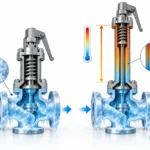
Manufacturers may use the same body or flange envelope for more than one internal orifice. The visible inlet and outlet can therefore remain unchanged while the nozzle throat, seat geometry, disc holder, guide and lift change. Different product series may also use different coefficients, blowdown arrangements and certification bases.
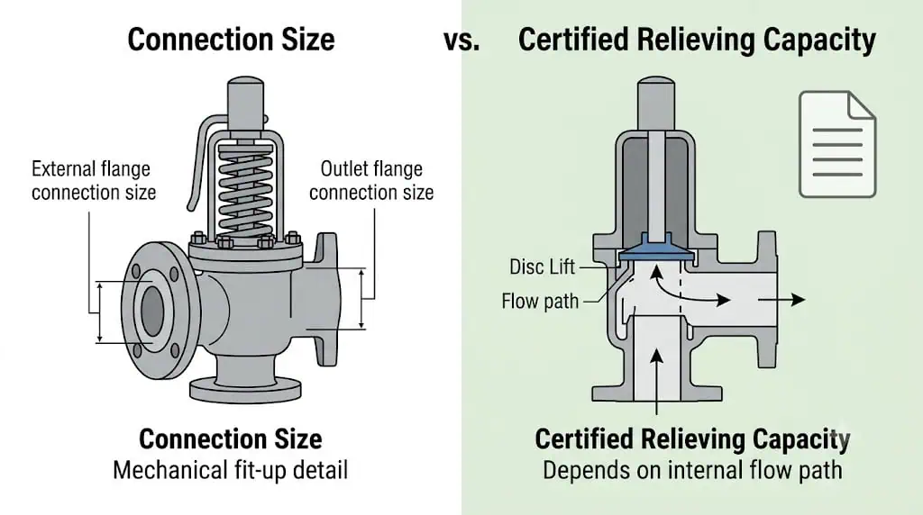
The illustration explains the selection principle; it is not a certified manufacturing drawing.
| Factor | How It Changes the Capacity Decision |
|---|---|
| Nozzle or effective orifice area | A larger supported flow area can pass more fluid when the remaining sizing conditions are comparable. |
| Valve lift and disc geometry | The available curtain area and flow path influence the discharge performance of the selected design. |
| Medium and phase | Steam, gas, vapor and liquid require different fluid properties and sizing treatment. Two-phase service may require a project-approved method. |
| Set and relieving pressure | The pressure available during relieving affects the supported flow and must match the calculation basis. |
| Relieving temperature | Temperature changes density and other fluid properties and may also limit materials or soft-seat components. |
| Back pressure | Superimposed and built-up back pressure can affect capacity and stability, particularly for conventional spring-loaded designs. |
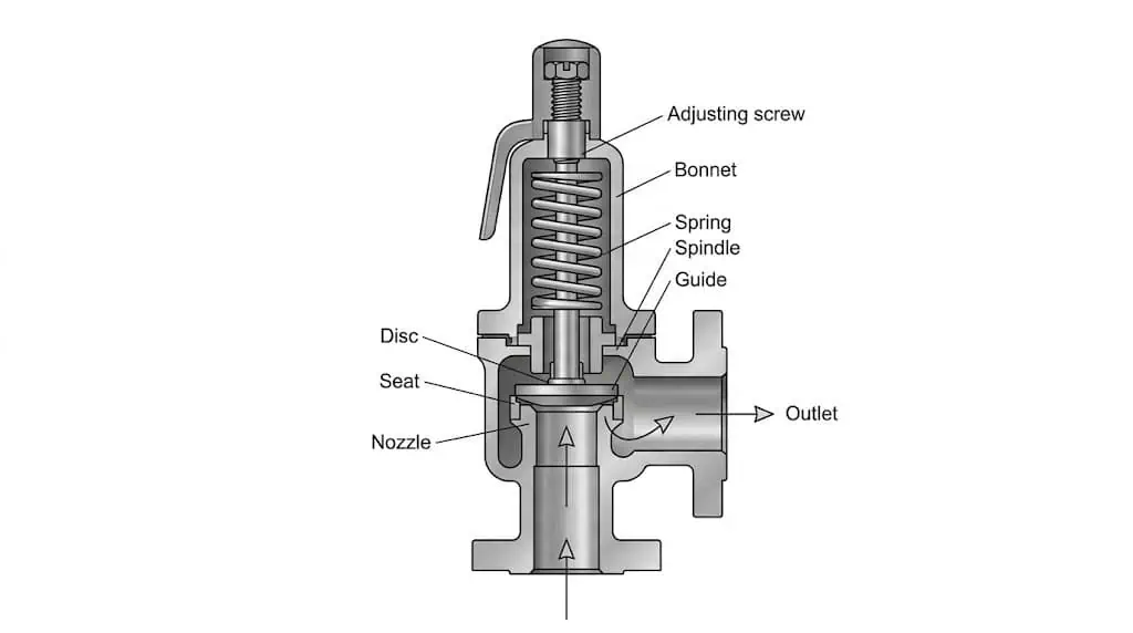
Replacement example: same 2 × 3 connection, different internal orifice
A buyer requests a 2 × 3 in spring-loaded safety valve at the existing set pressure. Two quotations fit the same flanges, but the selected orifices and documented capacities are different. Approving the lower-priced valve by connection size alone can create an undersized replacement.
Correct action: identify the protected equipment and governing relief case, confirm the required load, then compare that load with the exact model/orifice capacity. Approve the 2 × 3 connection only after the capacity check passes.
Required Relieving Capacity vs Certified or Supported Valve Capacity
Safety valve selection is a demand-versus-capability comparison. The required relieving capacity comes from the protected system and its governing overpressure scenario. The supported valve capacity comes from the selected valve design under defined conditions. The connection size belongs to the piping review and cannot replace either side of this comparison.
| Engineering Question | Required Evidence | Approval Boundary |
|---|---|---|
| What must be relieved? | Protected equipment, governing scenario, medium/phase and approved required load | Hold if the relief scenario or required flow is missing |
| At what conditions? | Set pressure, allowable overpressure or accumulation basis, relieving pressure and relieving temperature | Hold if pressure terms or units are mixed |
| Can the selected valve pass that load? | Exact model, orifice, capacity source, fluid basis and applicable corrections | Hold if capacity is copied from another model or inferred from size |
| Will it work when installed? | Inlet pressure-loss review, outlet back pressure, discharge routing, drainage and support | Hold if installed conditions differ from the capacity basis |
| Will it fit the piping? | Connection size, rating, facing, dimensions and material compatibility | Mechanical approval does not release an open capacity hold point |
Capacity comparisons must use the same basis
Before comparing required and supported capacity, align the units, fluid basis, relieving pressure, temperature and back-pressure assumptions. Do not compare kg/h with Nm³/h without a documented conversion. Do not apply an air capacity value directly to steam, liquid or a process gas. Do not introduce an arbitrary margin merely to make the selected valve appear acceptable.
For back-pressure effects, see ZOBAI’s back pressure and bellows guide. For installation limits, see the safety valve installation guide.
What API 526 Does—and Does Not—Prove
API 526 is commonly used for standardized flanged steel pressure relief valve dimensions and designated orifice families within its scope. This standardization helps engineers and buyers compare envelope dimensions, connection combinations and orifice designations. It does not mean that every valve with the same inlet/outlet size automatically has the same certified capacity.
API 526 can support
- standardized dimensional and connection communication;
- orifice designation discussions within the standard’s scope;
- replacement-envelope and piping coordination;
- more consistent RFQ comparison.
API 526 does not replace
- the governing relief calculation;
- manufacturer capacity data for the exact selected valve;
- medium, pressure and temperature verification;
- back-pressure and inlet-loss review;
- project code and certification requirements.
Use the API 526 flanged safety valve guide for dimensional and orifice-family context. Use the broader sizing guide when a formal capacity workflow is required.
Correct Safety Valve Selection Workflow
- Identify the protected equipment. Confirm the boiler, vessel, exchanger, compressor, pipeline, tank or skid tag.
- Identify the governing relief scenario. Examples include blocked outlet, fire exposure, regulator failure, thermal expansion or tube rupture.
- Confirm the required relieving load. Record the value, units and calculation basis.
- Define the relieving conditions. Confirm medium, phase, set pressure, relieving pressure, temperature and allowable overpressure basis.
- Select the valve design and orifice. Compare the exact supported capacity with the approved required load.
- Review installation effects. Check inlet pressure loss, outlet back pressure, discharge routing, support and drainage.
- Confirm the connection and documentation. Verify size, rating, facing, dimensions, materials, tests, markings and certificates.
Purchase-order hold point: commercial comparison may begin before every technical item is closed, but the final model and orifice should not be frozen while the required load, capacity basis or installation condition remains unverified.
For spring-loaded valve configuration, review spring-loaded safety valves. When the outlet system creates significant or variable back pressure, compare conventional, balanced-bellows and pilot-operated designs rather than assuming a construction name solves every condition.
Replacement Verification: Do Not Replace by Size Alone
An old valve nameplate and flange measurement are useful identification inputs, but they do not prove that the old valve was correctly sized or remains suitable after process changes. Debottlenecking, higher heat input, control-valve changes and discharge-header modifications can invalidate the original capacity or installation basis.
| Replacement Check | Minimum Data | Proceed or Hold |
|---|---|---|
| Installed valve identification | Nameplate, model, serial number, clear photos, inlet/outlet size and rating | Proceed for identification only |
| Protected equipment | Equipment tag, MAWP/design pressure, service and existing datasheet | Hold if the protected duty is unknown |
| Relief basis | Governing scenario and required capacity with units | Hold if capacity is missing or outdated |
| Selected replacement | Exact model, orifice and supported capacity | Hold if the offer only states connection size and set pressure |
| Installation | Inlet line, reducers, outlet header, back pressure, supports and drainage | Review before final release |
| Documentation | Datasheet, drawing, capacity evidence, test reports, material records and marking | Define before purchase-order release |
Management-of-change trigger: recalculate and revalidate the valve whenever process capacity, heat input, protected equipment, set-pressure basis, relief scenario or discharge system changes.
RFQ Checklist for Capacity and Connection Review
A useful RFQ must give the supplier enough information to select an orifice and verify capacity. “DN50 × DN80, 10 bar” is not a complete safety valve specification.
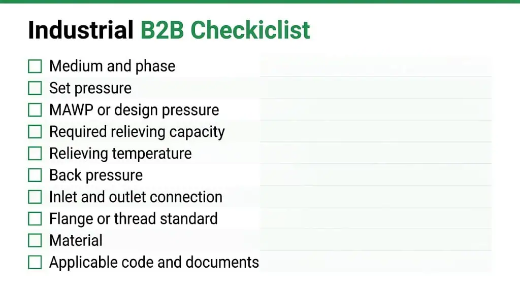
| RFQ Parameter | What to Provide | Why It Matters |
|---|---|---|
| Protected equipment and scenario | Equipment tag and governing overpressure case | Defines the protection duty |
| Medium and phase | Steam, gas, vapor, liquid or approved two-phase basis; composition/properties where needed | Controls sizing method and material review |
| Pressure data | Operating pressure, MAWP/design pressure, set pressure and allowable overpressure basis | Defines the pressure boundary and available relieving pressure |
| Required relieving capacity | Flow value, units, calculation revision and relieving conditions | Provides the demand that the valve must cover |
| Relieving temperature | Temperature at the governing relief condition | Affects fluid properties and component limits |
| Back pressure | Superimposed and built-up values, including constant or variable range | Affects construction, capacity and stability |
| Connections | Inlet/outlet size, standard, rating, facing and dimensional constraints | Supports fit-up and piping review |
| Materials and documents | Body/trim/seat requirements, applicable standard, tests, certificates and inspection scope | Supports technical and QA approval |
Unknown values should be marked “to be confirmed”. They should not be silently estimated from an old valve photograph or nominal pipe size.
Five Common Selection Mistakes
1. Treating DN/NPS as flow capacity
Nominal size is a piping designation, not a certified flow value.
2. Using set pressure as the sizing result
Set pressure defines the opening adjustment; it does not define the governing relief load.
3. Reusing capacity from another medium
Air, steam, gas and liquid capacity values are not interchangeable without the correct method and properties.
4. Ignoring back pressure
Outlet-system pressure can change capacity and valve stability even when the flange and orifice appear acceptable.
5. Replacing by appearance
The old valve may have been incorrectly selected or may no longer match the current process duty.
Approval rule
Require a traceable chain from relief calculation to selected model/orifice, capacity evidence, drawing, nameplate and test documentation.
Technical Reference Boundary
API 520, API 526, ASME BPVC Section XIII, National Board certification information and ISO 4126 may support different parts of a pressure-relief review. None of them makes connection size a substitute for required or supported capacity. Use the edition and jurisdiction adopted by the project.
FAQ
Is safety valve connection size the same as capacity?
No. Connection size describes the inlet and outlet piping interface. Capacity depends on the selected internal orifice, valve design, medium, pressure, temperature, back pressure and supported performance data.
Can two 2 × 3 safety valves have different capacities?
Yes. They may use different internal orifices, lift characteristics, coefficients, trims or certified designs even though the external inlet and outlet sizes match.
What is more important: connection size or orifice size?
They serve different purposes. Connection size is essential for piping fit and installation. Orifice and supported capacity are central to proving that the valve can relieve the required load.
Does API 526 orifice size automatically prove capacity?
No. API 526 supports standardized dimensional and orifice-designation communication within its scope. The exact selected valve capacity must still be verified for the applicable medium and relieving conditions.
Is set pressure enough to select a safety valve?
No. Set pressure does not define the required relieving load. Selection also needs the governing scenario, required capacity, medium, relieving temperature, allowable overpressure, back pressure and installation conditions.
Can I replace an old safety valve using only its nameplate and flange size?
No. Use the nameplate for identification, then confirm the protected equipment, current relief scenario, required capacity, exact replacement orifice, supported capacity and installed piping condition.
Can air capacity be used for steam, gas or liquid service?
Not directly. Capacity must be reviewed using the actual medium, phase, properties, pressure and temperature basis. Different media require the appropriate calculation or supported data.
What should a supplier provide to prove capacity?
The supplier should identify the exact model and orifice and provide the applicable certified or manufacturer-supported capacity source, units, medium basis, pressure and temperature conditions, and any approved correction factors.
Confirm the Orifice and Capacity Before Ordering
Send ZOBAI the protected equipment, relief scenario, required flow, set pressure, medium, relieving temperature, back pressure and connection requirements. The review should identify the selected valve model, orifice and supported capacity—not only the flange size.