Share your medium, set pressure, temperature, size, standard, or datasheet, and our team will review your requirement and respond with the appropriate next step.
Why Safety Valves Leak After Popping: Common Causes and Fixes
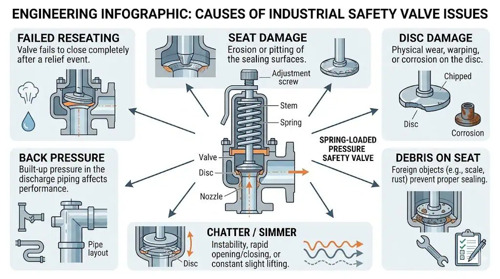
A safety valve usually leaks after popping because the disc does not return to a clean, aligned, and stable reseating condition. Debris may become trapped between the disc and nozzle seat during discharge. Chatter or flutter may damage the sealing surfaces. Excessive inlet pressure loss or outlet back pressure may destabilize closing. Operation too close …
A safety valve usually leaks after popping because the disc does not return to a clean, aligned, and stable reseating condition. Debris may become trapped between the disc and nozzle seat during discharge. Chatter or flutter may damage the sealing surfaces. Excessive inlet pressure loss or outlet back pressure may destabilize closing. Operation too close to set pressure may have already caused simmer and progressive seat wear before the reported lift event. Corrosion, thermal distortion, pipe strain, guide friction, unsuitable trim materials, or poor repair control can produce the same visible symptom.
Post-lift leakage should therefore be treated as both a valve-condition problem and a pressure-relief-system problem. Cleaning or re-lapping may stop the immediate leak, but it will not prevent recurrence if the real cause is an oversized orifice, restrictive inlet piping, a modified discharge header, unsuitable operating margin, dirty service, incorrect blowdown, or a valve type that no longer matches the actual relieving conditions.
The first engineering questions are:
Is the fluid actually passing through the valve seat, or is the leak coming from a flange, bonnet gasket, drain, vent, body pressure boundary, or nearby connection?
Did the valve complete one stable relief cycle, or did it simmer, flutter, or chatter?
Did the process pressure fall below the expected reseating region?
Was the outlet back pressure different from the original design basis?
Could debris, corrosion products, weld scale, polymer, condensate, or solids have crossed the seat?
Has the normal operating pressure moved closer to set pressure?
Does the valve still have enough certified relieving capacity for the current process duty?
Was the valve previously repaired, recalibrated, documented, and resealed under the required quality system?
Engineering warning: A safety valve that leaks after lift should not be dismissed as a minor nuisance. It may be the first visible evidence of damaged sealing surfaces, unstable valve action, changed back pressure, inadequate operating margin, contamination, unsuitable materials, or an incorrect valve-selection basis.
Post-lift leakage may originate from the seat, internal alignment, process contamination, operating margin, inlet pressure loss, outlet back pressure, materials, or previous repair work.
Poor Reseating After Lift
Reseating is the part of the relief cycle in which the disc returns to the nozzle seat after system pressure falls through the valve’s closing or blowdown range. A valve can open at the specified set pressure and still fail to reseat correctly. Set-pressure accuracy and reseating quality are related, but they are not the same performance characteristic.
Poor reseating can occur when:
The disc lands off-center because the spindle, guide, or disc holder is worn, bent, corroded, fouled, or incorrectly assembled.
Debris remains on the sealing line after the relieving flow stops.
The nozzle or disc has been scored, pitted, eroded, wire-drawn, or hammered by chatter.
Back pressure changes the force balance during closure.
Inlet pressure loss causes repeated opening and closing before the process pressure stabilizes.
Blowdown components or adjusting rings have been altered without an approved procedure.
Pipe strain or an unapproved mounting orientation creates side loading.
The process pressure does not fall far enough below the valve’s opening region.
The spring is only one part of this closing sequence. Spring force may be correct while guide friction, damaged seat geometry, outlet pressure, deposits, or piping loads prevent the disc from returning squarely to the nozzle.
Composite engineering scenario: A steam safety valve lifted at the expected set pressure during a process upset but continued passing afterward. The maintenance team initially increased attention on the spring setting. Shop inspection found the spring within the approved range, but the disc holder showed guide marks and the seat contained metallic debris. The upstream line had not been adequately cleaned after maintenance. The corrective action was to clean the pressure path, restore the seating surfaces, verify spindle and guide alignment, perform set-pressure and seat-tightness tests, document the repair, and reseal the adjustment before return to service.
Temporary Leakage vs Permanent Damage
A brief reduction in leakage after the system stabilizes does not prove that the valve remains fit for service. Soft contamination may move away from part of the seating line, or thermal conditions may change as the system cools, making the visible leak smaller. That is different from demonstrating acceptable seat tightness and reliable future operation.
Temporary or condition-dependent leakage is more likely when:
The leak began immediately after a first startup or commissioning lift.
The service contains loose scale, soft deposits, condensate, or construction debris.
Leakage decreases significantly as temperature and system pressure stabilize.
No chatter, severe vibration, abnormal noise, or repeated cycling was reported.
Inspection finds no scoring, pitting, erosion, deformation, or misalignment.
Permanent damage is more likely when:
Leakage continues well below the expected reseating pressure.
The valve chattered, fluttered, or repeatedly lifted.
The discharge contains hard solids, rust, weld slag, scale, coke, crystals, or corrosive products.
The disc or nozzle shows scoring, wire drawing, pitting, impact marks, or uneven contact.
The valve has a history of repeated leakage after previous repairs.
Operating pressure remains close to set pressure and simmer is ongoing.
The guide, spindle, spring, bellows, or soft parts show deterioration.
Any attempt to clear or exercise the valve while the system is pressurized must follow the approved plant procedure, manufacturer instructions, and jurisdictional requirements. Unplanned manual lifting, striking, tightening, or field adjustment can worsen seat damage, alter the setting, create an uncontrolled release, or invalidate the repair and sealing basis.
Decision boundary: A leak that becomes smaller is not automatically a safe leak. Continued operation requires a documented risk decision, an available independent protection path where required, and compliance with site and regulatory procedures.
System Problems Behind the Valve
Experienced troubleshooting starts by asking what changed in the protected system, not only what failed inside the valve. The valve may be responding to conditions that were not present during original selection or bench testing.
Important questions include:
Has process throughput increased since the original relief calculation?
Has normal operating pressure moved closer to the set pressure?
Was a compressor, pump, control valve, exchanger, regulator, or heat source modified?
Was the outlet line lengthened, reduced, connected to a silencer, or tied into a common flare or vent header?
Can another relieving device now create variable superimposed back pressure?
Was the inlet branch changed, restricted, insulated incorrectly, or allowed to collect deposits?
Has the fluid composition become dirtier, more corrosive, more viscous, or more likely to flash?
Was the valve replaced by nominal connection size without rechecking effective orifice and certified capacity?
Was the valve installed in a different orientation or subjected to unsupported outlet-piping loads?
A leak after popping may therefore be the final symptom of an earlier design or operating change. Repairing the seat without reviewing the changed system can return the valve to the same failure mode.
Composite engineering scenario: A conventional spring-loaded valve operated acceptably for several years. After a flare-header expansion, the valve began to flutter during relief and leak after reseating. Its set pressure and internal parts had not initially changed. The new header arrangement increased variable built-up back pressure during simultaneous relief. The corrective action was to revalidate the outlet hydraulics, inlet pressure loss, required capacity, and valve configuration before selecting a balanced or otherwise suitable replacement.
Common Root Causes of Leakage After Popping
Seat and Disc Damage
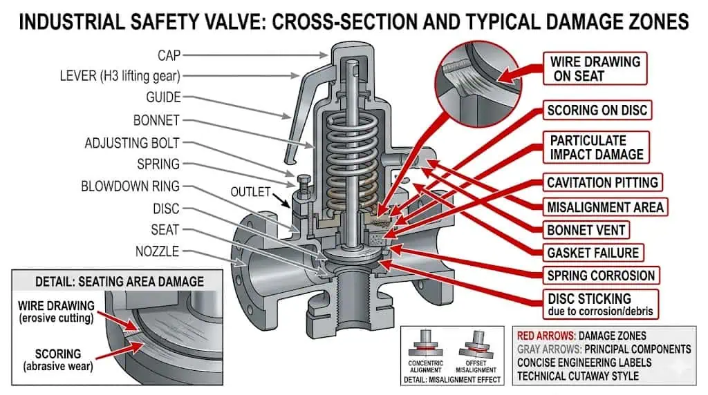
The nozzle seat and disc form the primary sealing interface, so even small changes in geometry can create persistent post-lift leakage. A properly designed pop event does not automatically damage a safety valve. Damage usually develops when the lift or closing process is unstable, the fluid contains damaging particles, the materials are unsuitable, or the valve has already been weakened by simmer, corrosion, thermal distortion, or previous repair.
Common damage mechanisms include:
Scoring: Linear damage caused by hard debris or sliding contact across the sealing surface.
Wire drawing: Localized erosion created by high-velocity leakage through a small seat opening.
Pitting: Local corrosion that interrupts the continuous sealing line.
Impact marking: Damage caused by chatter or hard, off-center reseating.
Thermal distortion: Uneven expansion that changes disc-to-nozzle contact.
Galling: Adhesive wear between unsuitable or poorly lubricated metallic surfaces.
Uneven lapping: Repair work that changes flatness, contact width, surface finish, or alignment.
Inspection should assess the full sealing line, disc alignment, nozzle condition, guide freedom, debris pattern, erosion, corrosion, and evidence of chatter—not only the spring setting.
A valve may pass a set-pressure test and still fail a seat-tightness requirement because the tests answer different questions. Set-pressure testing confirms the specified opening adjustment. Seat-tightness testing evaluates leakage at the specified test condition. Neither test alone demonstrates that the valve has sufficient relieving capacity for the current process scenario.
New or recently serviced safety valves frequently leak after their first lift because the process system—not the valve age—introduced contamination across the seat. A new valve can be damaged during its first discharge if the upstream line contains construction or maintenance debris.
Typical contaminants include:
Weld slag and grinding particles.
Rust flakes and mill scale.
Pipe dope, thread sealant, gasket fragments, and packing debris.
Corrosion products and salt crystals.
Coke, polymer, wax, resin, or sticky process residue.
Sand, catalyst, scale, or solid product particles.
Condensate carrying particles into the seating area.
Ice or hydrates in cold gas and cryogenic systems.
Contamination can affect more than the seat. Deposits in the guide or spindle area add friction and can prevent centered closing. Deposits in a pilot-operated valve’s sensing line, filter, pilot seat, or control passages can delay main-valve closure or create unstable operation.
Composite engineering scenario: A pilot-operated safety valve was installed in a dirty hydrocarbon service to improve tight shutoff near set pressure. After several operating cycles, the valve became slow to reseat and showed intermittent leakage. Condensate and solids had entered the pilot circuit and control passages. The corrective action included cleaning and redesigning the sensing arrangement, reviewing filtration and drainage, and reassessing whether the pilot-operated design was sufficiently tolerant of the actual medium.
Prevention requires line cleanliness, flushing discipline, preservation, suitable temporary strainers only where approved, contamination control during maintenance, and a valve design that matches the actual fouling risk. A permanent unreviewed strainer in a safety-valve inlet can itself become a restriction and should not be added as an improvised solution.
Back Pressure and Inlet Pressure Loss
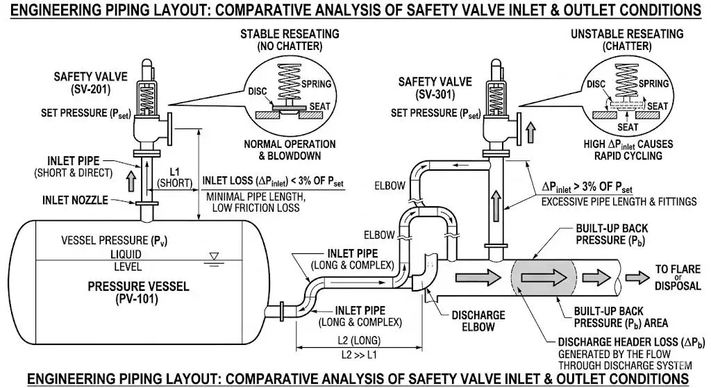
Inlet pressure loss and outlet back pressure can damage the seat indirectly by making the opening and closing sequence unstable. They can also prevent the disc from returning to the seat under a predictable force balance.
Inlet pressure loss develops when relieving flow passes through a restrictive branch, long inlet line, reducers, elbows, partially open isolation valve, fouled connection, rupture-disk arrangement, or undersized nozzle connection. When the valve opens, the pressure at its inlet may fall faster than pressure in the protected equipment. The valve begins to close, inlet pressure recovers, and the valve opens again. Repeated impact can rapidly damage the seat and disc.
Back pressure includes:
Superimposed back pressure: Outlet pressure present before the valve opens. It may be constant or variable.
Built-up back pressure: Outlet pressure generated after opening by relieving flow through the tailpipe, fittings, silencer, header, scrubber, vent, or flare system.
Depending on valve design, back pressure can affect opening behavior, lift, effective capacity, blowdown, closing force, and reseating. A conventional spring-loaded valve, balanced bellows valve, and pilot-operated valve do not have identical back-pressure limits or correction requirements.
A valve can be correctly calibrated and still leak after relief when inlet pressure collapses during flow or the outlet system imposes unstable or excessive back pressure.
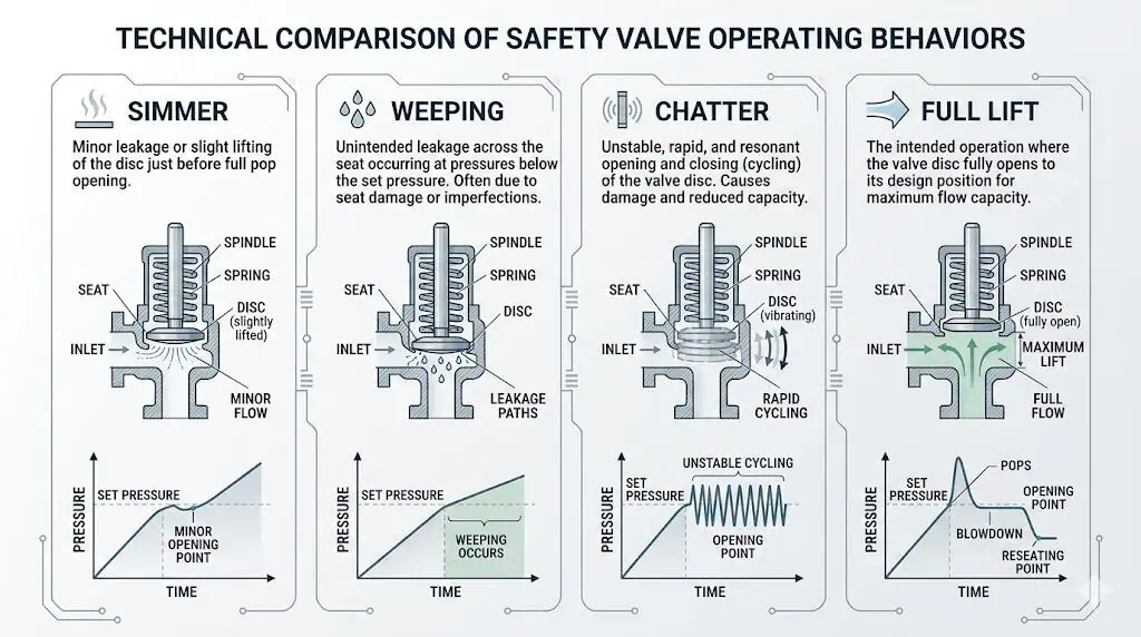
Long-term operation close to set pressure can damage seat tightness before any obvious full-lift event occurs. Small pressure fluctuations, pulsation, vibration, or thermal changes can produce simmer or micro-lift. High-velocity fluid then passes through a very small opening and progressively erodes the sealing surfaces.
The relevant pressure terms should be separated:
Operating pressure: The pressure experienced during normal service.
Set pressure: The pressure at which the valve is adjusted to begin its specified opening response under defined conditions.
Overpressure: The pressure increase above set pressure while the valve is relieving.
Accumulation: The pressure increase above the protected equipment’s MAWP or other allowable pressure boundary during the event.
Blowdown: The difference between set pressure and reseating pressure.
Operating margin: The separation between normal operating pressure and the valve’s opening region.
There is no universal operating-margin percentage suitable for every valve and service. The acceptable margin depends on valve design, seat type, process stability, pressure pulsation, fluid cleanliness, temperature, back pressure, required tightness, blowdown, manufacturer data, and project requirements.
Simmer and repeated unstable movement can erode the seat before a major relief event. Full lift does not prove that the valve will reseat tightly afterward.
Composite engineering scenario: A gas receiver safety valve repeatedly passed workshop testing but developed leakage shortly after returning to service. Operating records showed that receiver pressure remained near set pressure and compressor pulsation produced frequent peaks. The corrective action was to review pressure-control stability, operating margin, seat configuration, and valve selection rather than repeatedly re-lap the seat.
How Engineers Diagnose a Leaking Safety Valve
Confirm the Leak Path First
The first diagnostic step is to confirm whether the leak actually passes through the closed valve seat. Steam, gas, or liquid found near a safety valve does not automatically prove seat leakage. The leak may originate from the pressure boundary, bonnet joint, flange gasket, threaded connection, drain, vent, pilot tubing, test connection, or adjacent piping.
Leak Type
Likely Location
Typical Indicators
Initial Review
Seat leakage
Valve outlet or discharge piping while the valve should be closed.
Continuous or intermittent passing downstream of the seat.
Confirm system pressure, outlet pressure, temperature, and whether another connected valve can backflow.
Body pressure-boundary leakage
Body wall, casting, forging, drain boss, or pressure-containing connection.
Localized wetting, gas indication, crack line, corrosion or seepage.
Remove from service under the approved procedure and evaluate pressure-boundary integrity.
Bonnet or cover-joint leakage
Bonnet gasket, bolted joint, cap, or cover.
Residue, wetness, vapor, or gas around the joint.
Check gasket, bolting, thermal effects, assembly and process exposure.
Check gasket, alignment, torque procedure, weld condition and pipe strain.
Bellows bonnet-vent leakage
Balanced-valve bonnet vent.
Process fluid or pressure at the vent.
Investigate possible bellows failure and route hazardous venting safely.
Pilot-system leakage
Pilot seat, sensing line, fittings, filter or control chamber.
Leakage or unstable main-valve pressure control.
Inspect pilot components, contamination, drainage, blockage and seals.
Confirming the path prevents unnecessary valve disassembly and avoids overlooking a more serious body, flange, bellows, or connection defect. The inspection method must suit the fluid hazard; toxic, flammable, high-temperature, cryogenic, or oxygen service requires approved detection and isolation procedures.
Review Lift History and Operating Margin
The event history often identifies whether the leak was caused by one damaging lift or by a longer period of unstable operation.
Review:
The date, duration, and estimated pressure of the relief event.
Whether the valve reached stable lift or repeatedly cycled.
Process pressure before and after the event.
Whether pressure fell below the expected reseating region.
Normal operating pressure and pressure fluctuations over time.
Recent startup, shutdown, trip, maintenance, flushing, or process changes.
Changes to the flare, vent, silencer, common header, tailpipe, or discharge destination.
Changes to inlet piping, isolation valves, rupture disks, or upstream fouling.
Previous as-found set pressure and leakage results.
Previous seat repairs, lapping, spring replacement, trim replacement, or repeat complaints.
Evidence of vibration, pipe movement, noise, reaction loading, or liquid accumulation.
Repeated leakage after multiple repairs is a strong reason to investigate the process and piping rather than treating each event as an isolated valve defect.
Bench Test Results vs Field Performance
A bench test is necessary evidence, but each test proves only the characteristic covered by its procedure.
Test or Evidence
What It Confirms
What It Does Not Confirm
Set-pressure test
The specified opening adjustment under controlled test conditions.
Installed-system stability, certified capacity, or acceptable piping.
Seat-tightness test
Leakage performance at the specified test pressure, medium, and method.
Required relieving capacity or field reseating under all process conditions.
Certified or accepted capacity data
Documented flow performance of a defined valve, orifice, fluid, and configuration.
That the plant relief scenario or installation calculation is correct.
Installation review
Whether inlet loss, outlet back pressure, orientation, drainage, and support are acceptable.
Internal condition after long service.
As-found inspection
Actual valve condition and setting when removed from service.
Future reliability unless the root cause is corrected.
Repair and recalibration record
Parts replaced, work performed, final tests, adjustment and seal status.
That the original process or piping cause has been eliminated.
Field conditions can introduce thermal distortion, process contamination, superimposed and built-up back pressure, inlet pressure loss, vibration, pulsation, pipe strain, weather, condensate, corrosion, and repeated cycling that are absent from a shop test.
A valve that repeatedly passes bench testing but leaks in one installed location should trigger a system review. A valve that leaks on the bench as found requires internal condition and maintenance review as well.
Common Root-Cause Patterns
Root Cause
Typical Evidence
Likely Result
Corrective Direction
Disc misalignment or guide friction
Uneven contact pattern, guide marks, bent spindle, deposits or galling.
Incomplete or off-center reseating.
Inspect alignment, clearances, materials and assembly; replace damaged parts and remove the side-load cause.
Seat or disc damage
Scoring, pitting, erosion, wire drawing, impact marks or uneven lapping.
Persistent seat leakage.
Restore within approved dimensional limits or replace trim; identify what caused the damage.
Startup contamination
Weld slag, rust, scale, gasket debris or construction particles.
Immediate leakage after the first lift.
Clean the system and valve; improve flushing, preservation and commissioning controls.
Dirty or polymerizing service
Deposits in the nozzle, guide, disc holder or pilot passages.
Restricted movement, delayed closure or recurring leakage.
Review valve type, clearances, materials, flushing and maintenance interval.
Excessive inlet pressure loss
Long or restrictive inlet, repeated chatter, pressure collapse during flow.
Disc impact and rapid seat damage.
Redesign or analyse the inlet arrangement and confirm the selected orifice.
Superimposed or built-up back pressure
Common header, flare change, long outlet, silencer or variable downstream pressure.
Unstable lift, altered blowdown, poor reseating or reduced capacity.
Recalculate the outlet system and review conventional, balanced or pilot construction.
Operating pressure too close to set pressure
Frequent simmer, pulsation and leakage without a major relief event.
Progressive seat erosion and nuisance leakage.
Restore suitable operating margin and improve process-pressure control.
Incorrect blowdown or internal adjustment
Long discharge, premature closure, cycling or altered ring settings.
Poor process recovery or unstable reseating.
Return adjustment to the approved manufacturer and test basis.
Unsuitable materials
Localized corrosion, galling, soft-seat swelling or spring deterioration.
Leakage, sticking, set-pressure drift or shortened life.
Review every relevant component, not only the body material.
Pipe strain or wrong orientation
Body distortion, flange misalignment, side loading or retained liquid.
Uneven seat contact and leakage.
Correct support, alignment, mounting orientation, drainage and thermal movement.
Oversized valve or orifice
Valve opens but flow cannot sustain stable lift.
Cycling, chatter and seat damage.
Revalidate required capacity and select a suitable certified orifice.
Incomplete repair control
Unknown parts, no as-found data, no final test or missing seal.
Uncertain setting, leakage and poor traceability.
Use an approved repair process, testing, documentation and resealing route.
This table supports initial troubleshooting only. Final conclusions depend on the medium, pressure, temperature, back pressure, valve type, installation, previous history, applicable code, and physical inspection results.
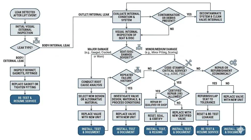
Repair, Rework, or Replacement
Repair is appropriate only when the damage is recoverable, the valve remains suitable for the duty, approved dimensional limits can be maintained, and the system cause has been addressed.
When Cleaning or Re-Lapping Still Makes Sense
Cleaning or controlled re-lapping may be appropriate when contamination or minor surface damage is localized and the valve remains suitable for the actual service. The decision should be based on inspection and approved manufacturer or repair procedures, not on the convenience of restoring a visible sealing line.
Cleaning or re-lapping is more defensible when:
The leak followed one identifiable contamination event.
Damage is superficial and within approved repair limits.
The disc, nozzle, guide, spindle, spring, bellows and body remain serviceable.
There is no evidence of severe chatter, deformation, cracking, deep corrosion, or material loss.
The original valve type and capacity remain correct for the process.
The system contamination or piping cause has been identified and corrected.
The repair organization can restore required geometry, finish, alignment and traceability.
Set-pressure and seat-tightness testing will be completed after assembly.
Repeated lapping can remove material and alter contact geometry. The nozzle and disc should not be reworked indefinitely. Manufacturer limits, minimum dimensions, hardness pairing, surface finish and component interchangeability must be respected.
Increasing spring compression to force the valve tighter is not an acceptable leakage repair unless it is part of an approved recalibration that remains within the protected-equipment and spring-range requirements. It can change set pressure and leave the equipment under-protected.
When Shop Inspection and Recalibration Matter
Shop inspection is required when the valve’s internal condition, setting, alignment, or failure mechanism cannot be established safely in service. The objective is not merely to stop the leak. It is to restore the complete opening, relieving and reseating function.
A controlled shop scope may include:
Identification, nameplate and service verification.
Recording the as-found seal condition and external condition.
As-found set-pressure and leakage testing where appropriate and safe.
Controlled disassembly with component identification.
Inspection of the nozzle, disc, guide, spindle, spring, bellows, gaskets, soft parts and adjustment components.
Dimensional, surface-condition and alignment checks.
Material verification or traceability review where required.
Cleaning and approved repair or replacement of damaged parts.
Verification that replacement components are approved for the exact model and service.
Reassembly using the specified procedure and torque controls.
Set-pressure verification using the approved test medium and correction basis.
Seat-tightness testing using the applicable project or API 527 basis.
Blowdown or operational testing where required by the valve and code route.
Final locking, sealing, tagging and documentation.
The as-found condition is valuable engineering evidence. A valve found significantly off set pressure, heavily corroded, contaminated, damaged by chatter, or repeatedly leaking may justify shorter inspection intervals or a system redesign.
Where the owner, jurisdiction, or NBIC route requires recognized pressure-relief-valve repair authorization, verify the repair organization’s National Board VR Certificate of Authorization.
When Replacement Is the Better Decision
Replacement is normally the better decision when reliable function cannot be restored within approved repair limits or when the existing valve no longer matches the process duty.
Replacement should be strongly considered when:
The nozzle, disc, guide, spindle, spring, bellows, body or bonnet has severe corrosion, erosion, cracking, deformation, or material loss.
Repeated seat repair has altered critical dimensions or produced recurring leakage.
The spring is damaged, corroded, relaxed, incorrect, or outside the approved range.
Parts are obsolete, unavailable, untraceable, or not approved for interchange.
The fluid, temperature, back pressure, operating pressure, throughput, or relief scenario has changed.
The required relieving capacity now exceeds the existing valve’s certified capacity.
The original valve type is unsuitable for variable back pressure, dirty service, corrosive media, high temperature, flashing flow, or another current condition.
The valve has repeated unexplained leakage or unstable operation despite competent repair.
The applicable code, owner standard, or documentation requirement can no longer be satisfied.
The consequence of another failure is high and the remaining condition is uncertain.
A replacement should not be selected from connection size and set pressure alone. Required relieving capacity, effective orifice, opening characteristic, materials, back pressure, pressure-temperature rating, inlet and outlet piping, seat-tightness requirement, code marking and document package must be revalidated.
Maintain Proper Operating Margin Below Set Pressure
Preventing simmer and repeated micro-lift is one of the most effective ways to protect seat condition. Normal operating pressure and credible fluctuations should remain sufficiently below the valve’s opening region for the selected design and service.
Prevention measures include:
Trend actual operating pressure rather than relying only on nominal design values.
Review pressure pulsation from reciprocating compressors, pumps or unstable control loops.
Investigate repeated near-lift events, short-duration pressure peaks and nuisance releases.
Confirm the set-pressure basis remains compliant with the protected equipment’s MAWP and applicable code arrangement.
Do not raise set pressure simply to stop simmer unless the revised setting is independently approved.
Review whether a different seat construction or valve type is justified by the operating-pressure ratio and leakage requirement.
A pilot-operated valve may provide tight shutoff in suitable clean service, but small pilot passages and sensing systems can be vulnerable to dirt, condensation, freezing, wax, polymer and solids. A balanced bellows can reduce certain back-pressure effects, but it does not create operating margin or correct an oversized or restrictive system.
Reduce Chatter Risk Through Better Piping Design
Piping design directly affects whether the valve completes one stable opening and closing cycle or repeatedly impacts the seat.
Key checks include:
Keep the inlet path short, direct and non-restrictive where practical.
Evaluate inlet pressure loss at relieving flow, not only during normal operation.
Calculate superimposed and built-up back pressure for credible relief cases.
Include silencers, scrubbers, flare headers, common vents and simultaneous relief loads.
Support outlet piping independently and evaluate reaction, thermal, vibration and acoustic loads.
Provide drainage and avoid retained condensate or rainwater.
Install the valve in the manufacturer-approved orientation, usually with the spindle upright for direct spring-loaded designs.
Keep balanced-bellows bonnet vents open or route them according to the approved design.
Revalidate the system after process debottlenecking or piping modifications.
API 520 Part II is relevant to pressure-relieving-device installation and includes an engineering-analysis route for installations requiring more than a simple screening check. A familiar inlet-loss percentage should not be applied blindly to every valve, fluid or dynamic system.
Match Valve Type, Seat Construction, and Trim to the Medium
Recurring leakage often continues because the replacement duplicates the old connection and set pressure without correcting the original service mismatch.
The material and construction review should include:
Component
Leakage or Reliability Function
Selection Questions
Body and bonnet
Contain pressure and protect or expose internal parts.
Are pressure-temperature rating, external corrosion and bonnet arrangement suitable?
Nozzle and seat
Form the primary sealing line and flow entrance.
Are material, hardness, corrosion, erosion and repair limits suitable?
Disc and disc holder
Control opening, flow forces and reseating contact.
Can they resist impact, erosion, deposits and thermal distortion?
Guide and spindle
Maintain centered movement.
Are clearance, anti-galling pairing, fouling resistance and alignment suitable?
Spring
Provides calibrated closing force.
Are temperature, corrosion, relaxation, coating and spring range acceptable?
Bellows
Reduces certain back-pressure force effects and may isolate the spring chamber.
Are pressure, fatigue, corrosion, temperature and bonnet venting acceptable?
Metal seat
Supports high temperature and many severe services.
Can required tightness be achieved and maintained under the actual process?
Soft seat and O-rings
Can improve tightness in suitable clean services.
Are temperature, chemical compatibility, ageing, extrusion, decompression and fire exposure acceptable?
Gaskets and seals
Prevent external leakage at internal joints.
Are fluid compatibility, temperature and assembly controls defined?
A stainless-steel body does not prove that the nozzle, disc, guide, spring, bellows or soft parts are compatible. Sour service may require NACE MR0175 / ISO 15156 review where specified. High-temperature steam may require different seat, spring and gasket decisions from clean ambient gas. Chloride-bearing or acidic media may attack internal trim before visible body damage appears.
A repeat order should be treated as a fresh engineering review when the valve has leaked after popping, the failure cause is uncertain, or the process has changed. Repeating the old tag, connection size and set pressure may reproduce the same failure.
Before issuing the next RFQ or purchase order, confirm:
The protected equipment and governing overpressure scenario.
Normal operating pressure, MAWP or other allowable limit, set pressure, allowable overpressure or accumulation and blowdown requirement.
Fluid composition, phase, cleanliness, corrosivity, relieving temperature and possibility of flashing or two-phase flow.
Required relieving capacity and calculation basis.
Selected effective orifice and certified or project-accepted capacity.
Maximum, minimum and normal superimposed back pressure.
Calculated built-up back pressure and outlet-header condition.
Inlet pressure loss and piping geometry at relieving flow.
Whether conventional, balanced bellows or pilot-operated construction is appropriate.
Metal-seat or soft-seat requirement and specified seat-tightness test.
Pressure-relief-valve repair authorization and VR stamp.
Relevant where required by the owner, jurisdiction or NBIC repair route.
Safety valve leakage after popping usually indicates poor reseating, damaged or contaminated sealing surfaces, unstable opening or closing, unsuitable operating margin, inlet pressure loss, outlet back pressure, material deterioration, or incomplete repair control. Cleaning may correct a limited contamination problem, but repeat reliability comes from identifying and removing the actual failure mechanism.
The most effective corrective programme combines valve inspection with process-history review, certified-capacity verification, inlet and outlet piping analysis, material review, controlled repair, set-pressure testing, seat-tightness testing, documentation and resealing.
Final engineering conclusion: The plant that only re-laps a leaking valve often sees the leak return. The plant that reviews operating margin, relief load, inlet loss, back pressure, contamination, materials, installation and repair history has a much better chance of eliminating the recurrence.
FAQ
Why does a safety valve leak after popping?
A safety valve usually leaks after popping because it does not reseat cleanly or the sealing surfaces have been damaged. Common causes include debris, scoring, pitting, chatter, excessive inlet pressure loss, high or variable back pressure, operation too close to set pressure, guide misalignment, corrosion, pipe strain and poor repair control.
Can a leaking safety valve stay in service?
A leaking safety valve should not be assumed safe to remain in service. The decision depends on the leak path, fluid hazard, leakage rate, protected equipment, availability of independent pressure protection, site procedures and regulatory requirements. A valve that cannot reseat reliably requires prompt engineering and inspection review.
How can you tell whether leakage is temporary or permanent?
Persistent leakage well below the expected reseating pressure, repeated cycling, visible seat damage or recurring failure normally indicates more than temporary contamination. A reduction in leakage after pressure or temperature stabilizes does not by itself prove that the valve remains fit for service. Inspection and an approved seat-tightness test may be required.
Does a passed bench test prove the valve is fine?
No. A set-pressure test verifies opening adjustment under controlled conditions. A seat-tightness test verifies leakage under its specified test method. Neither test alone proves sufficient relieving capacity, acceptable inlet pressure loss, allowable outlet back pressure or stable field performance.
When is replacement better than repair?
Replacement is usually preferable when damage exceeds approved repair limits, corrosion affects multiple components, parts are obsolete, leakage repeatedly returns, required capacity has changed, or the original valve no longer suits the medium, back pressure, temperature or installation.
Can debris make a new safety valve leak after its first lift?
Yes. Weld slag, rust, scale, gasket fragments, construction debris and process solids can cross the seat during the first relief event and damage or block the sealing line. System cleanliness and commissioning controls are therefore critical even when the valve is new.
How does back pressure cause leakage after popping?
Back pressure can change the force balance, lift, blowdown and reseating behavior of the valve. Variable or excessive outlet pressure may prevent stable closure or contribute to chatter. Conventional, balanced bellows and pilot-operated designs have different back-pressure limits.
Can operating too close to set pressure damage the seat?
Yes. Insufficient operating margin can cause simmer or micro-lift. High-velocity leakage through a small opening progressively erodes the sealing surfaces and can cause a larger leak after the next full lift.
What is the difference between a set-pressure test and a seat-tightness test?
A set-pressure test checks when the valve begins its specified opening response. A seat-tightness test checks leakage while the valve is closed at a specified test condition. Neither test proves that the selected valve has enough certified capacity for the plant relief scenario.
Should the spring be tightened to stop a safety valve leak?
No unapproved spring adjustment should be used as a leakage repair. Increasing spring compression can raise set pressure and leave the protected equipment under-protected. Adjustment should only be performed under an approved calibration procedure followed by testing, locking, documentation and resealing.
What information should be reviewed before ordering a replacement?
Review the protected equipment, relief scenario, operating and set pressures, required capacity, certified capacity, effective orifice, fluid phase, temperature, back pressure, inlet and outlet piping, materials, seat type, code route, test requirements and repair history.
Related Engineering Guides
Continue with these focused guides when the broader selection or maintenance review reaches the corresponding application question:
To provide the best experiences, we use technologies like cookies to store and/or access device information. Consenting to these technologies will allow us to process data such as browsing behavior or unique IDs on this site. Not consenting or withdrawing consent, may adversely affect certain features and functions.
Functional
Always active
The technical storage or access is strictly necessary for the legitimate purpose of enabling the use of a specific service explicitly requested by the subscriber or user, or for the sole purpose of carrying out the transmission of a communication over an electronic communications network.
Preferences
The technical storage or access is necessary for the legitimate purpose of storing preferences that are not requested by the subscriber or user.
Statistics
The technical storage or access that is used exclusively for statistical purposes.The technical storage or access that is used exclusively for anonymous statistical purposes. Without a subpoena, voluntary compliance on the part of your Internet Service Provider, or additional records from a third party, information stored or retrieved for this purpose alone cannot usually be used to identify you.
Marketing
The technical storage or access is required to create user profiles to send advertising, or to track the user on a website or across several websites for similar marketing purposes.