Share your medium, set pressure, temperature, size,standard, or datasheet, and our team will review yourrequirement and respond with the appropriate next step.
What Is a Safety Valve and How Does It Work in Pressure Systems?
A safety valve is a self-actuated pressure-relieving device that opens when system pressure reaches a defined set pressure and closes again after pressure returns to an acceptable range. Its job is not simply to vent pressure. It must open at the correct set pressure, pass enough relieving flow, remain stable during discharge, and reseat without unacceptable …
A safety valve is a self-actuated pressure-relieving device that opens when system pressure reaches a defined set pressure and closes again after pressure returns to an acceptable range. Its job is not simply to vent pressure. It must open at the correct set pressure, pass enough relieving flow, remain stable during discharge, and reseat without unacceptable leakage. Many users ask what is a safety valve and confuse it with a relief valve, safety relief valve, pressure safety valve, or PSV because the external form can look similar. In real projects, that confusion leads to wrong service selection, weak documentation review, capacity shortfall, unstable operation, and poor field performance. A valve that looks correctly sized by connection or pressure rating can still fail the duty if required relieving capacity, certified capacity, back pressure, medium compatibility, installation layout, or repair traceability has not been checked.
Due to their similarities, safety valves and pressure relief valves are commonly interchanged in casual conversation. In engineering review, the difference matters because service medium, opening behavior, sizing basis, seat tightness, back pressure tolerance, and inspection acceptance may change with the selected device type.
Selecting the correct safety valve requires understanding set pressure, spring action, required relieving capacity, certified capacity, orifice area, overpressure, accumulation, blowdown, inlet pressure loss, back pressure, material compatibility, seat tightness, and reseating behavior. Not every valve with a suitable pressure class can ensure real overpressure protection.
What Is a Safety Valve
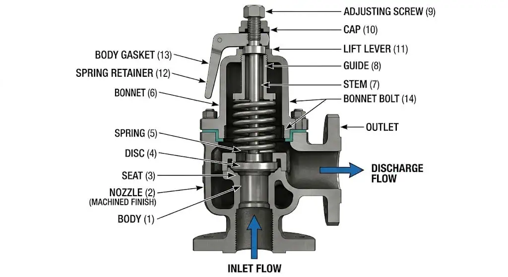
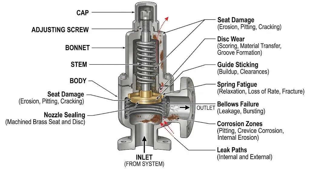
This structure overview shows the main internal components that control opening pressure, discharge path, reseating behavior, seat tightness, and long-term leakage performance.
Definition and Main Purpose
A safety valve is a device that automatically opens to release excess pressure and closes when the system returns to safe conditions. This function protects people, equipment, and the environment from dangerous overpressure. From an engineering perspective, the valve is only useful if it opens at the intended set pressure, discharges enough mass flow for the governing scenario, and reseats acceptably afterward. The valve must be selected for the protected equipment, not just for the pipe connection.
A safety valve is a self-actuated pressure-relieving device designed to discharge fluid so that a predetermined safe pressure is not exceeded, and to re-close afterward when normal pressure conditions are restored.
A safety valve acts as a final pressure boundary safeguard in boilers, pressure vessels, process equipment, gas systems, steam systems, storage vessels, and piping systems. It helps prevent dangerous pressure accumulation that could otherwise lead to rupture, fire escalation, release of hazardous fluid, production loss, environmental damage, or injury. In pressure-vessel service, the set pressure and certified relieving capacity must be tied to the protected equipment limit and the applicable code basis.
Composite field scenario for engineering training: A user selected a replacement valve based on inlet size and pressure class only. The new valve matched the flange and looked equivalent, but the certified relieving capacity was lower than the original valve. The set pressure was correct, yet the device could not satisfy the required relief load during final technical review. The problem was not the pressure class. It was that orifice area and certified capacity had not been checked against the actual overpressure case. The prevention is to compare required relieving capacity with certified relieving capacity before treating two valves as interchangeable. For more detail, see certified relieving capacity vs connection size.
Safety Valve vs Relief Valve vs Safety Relief Valve
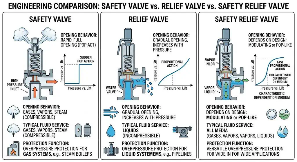
Understanding the differences between these valves is essential for correct system protection. The terms are often mixed in casual discussion, but they should not be treated as interchangeable during engineering review. The correct term affects service medium, opening behavior, sizing basis, testing expectation, and how the device is documented for inspection.
Valve Type
Typical Opening Behavior
Typical Service Basis
Why the Difference Matters
Safety Valve
Rapid or pop opening.
Compressible fluids such as steam, gas, or vapor.
Used where quick opening is needed to protect against sudden pressure rise.
Relief Valve
Gradual or proportional opening.
Incompressible liquid service.
More suitable for liquid overpressure control where modulation matters.
Safety Relief Valve
May serve either behavior depending on design and certification.
Gas, vapor, steam, or liquid depending on application and code route.
Useful when the service definition requires flexibility, but the duty must still be verified case by case.
Pressure Safety Valve / PSV
Plant term often used broadly.
Common in oil, gas, chemical, and process plants.
The datasheet still needs to define the actual device type, medium, set pressure, capacity basis, and standard route.
A safety valve usually refers to pop-action protection for compressible fluids. A relief valve is more associated with liquid service and proportional opening. A safety relief valve can be applied in gas, vapor, steam, or liquid service depending on design, medium, and code route. PSV is a common plant term, but it should not hide the actual engineering duty. For a deeper terminology review, see PRV vs PSV vs safety valve vs relief valve.
These valve terms are related but not interchangeable. Opening pattern, service medium, pressure-relief function, and certification route change the correct selection basis.
Types of Safety Valves
There are several types of safety valves, each with a different selection boundary. Users should not choose by catalog family alone. They should choose by medium, back pressure, leakage tolerance, service cleanliness, operating margin, maintenance capability, and project code basis.
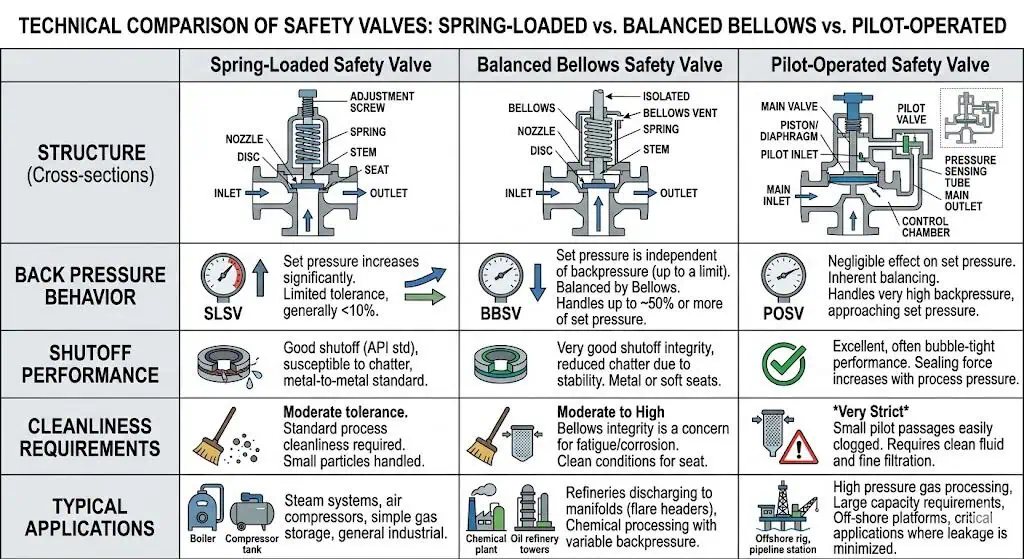
Spring-loaded safety valves: Use spring force to hold the disc closed until set pressure is reached. They are common in many general gas, steam, vapor, and process services.
Balanced bellows safety valves: Help isolate the spring chamber from discharge pressure and are often reviewed when back pressure is significant or variable.
Pilot-operated safety valves: Offer tight shutoff and can perform well in some high-pressure or high-capacity services, but dirty media, wax, hydrates, freezing, or unstable pilot conditions can become a limitation.
Safety relief valves: Applied where the duty may involve gas, vapor, steam, or liquid and the design is intended to serve the required response mode.
The table below highlights their main engineering differences:
Tighter shutoff, high operating pressure ratio, or special high-capacity review cases.
Pilot lines can foul, freeze, or become unstable in dirty service.
Safety relief valve
Design supports gas/vapor or liquid duty depending on selection.
Mixed duty review or broader service definition.
Still requires exact service validation and correct terminology.
Understanding what is a safety valve, how it differs from a relief valve, and where each type fits helps users avoid wrong valve selection at the quotation stage. This is especially important when normal operating pressure is close to set pressure, when outlet back pressure is variable, or when service contains corrosive, dirty, freezing, or polymerizing media.
Spring-loaded, balanced bellows, and pilot-operated safety valves do not serve the same operating boundary. Back pressure, shutoff behavior, service cleanliness, and maintenance capability all affect the right choice.
How Does a Pressure Safety Valve Work
Operating Principle
A pressure safety valve works by balancing system pressure against a closing force, then opening automatically when the pressure reaches the valve’s set point. This operating principle provides overpressure protection without external power. In a conventional spring-loaded design, the spring keeps the disc on the seat during normal operation. When system pressure creates enough upward force on the disc, the valve lifts and releases fluid.
The valve stays closed because the spring force is greater than the upward force created by system pressure on the disc.
When pressure rises to the set pressure, the forces reach the opening condition.
The valve lifts and releases fluid fast enough to prevent the protected system from exceeding its allowable pressure boundary.
The valve must pass the required relieving capacity during the governing case, not just crack open.
After pressure falls to the reseating range, the spring closes the valve again.
This cycle is simple in concept, but performance depends on real service conditions such as inlet pressure loss, discharge back pressure, medium properties, trim condition, corrosion, fouling, and seat tightness. A valve can open on a test stand and still chatter in service if the installed inlet and outlet piping are outside the stable operating boundary.
Key Components
A safety valve consists of several main components, and each one affects performance, leakage, and maintenance.
Component
Role
Why It Matters to the User
Body
Pressure-retaining housing for all internal parts.
Must suit pressure, temperature, corrosion, external environment, and code basis.
Disc
Moves away from the seat to allow discharge.
Damage, fouling, erosion, or corrosion can cause leakage or unstable lift.
Seat / Nozzle
Sealing surface against the disc and primary flow entrance.
Controls seat tightness and influences long-term leakage behavior.
Spring
Provides closing force and establishes set pressure.
Affects opening point, reseating behavior, and recalibration after service.
Guide / Stem
Keeps moving parts aligned.
Wear, corrosion, or deposits can cause sticking, chatter, or poor reseating.
Bellows (if fitted)
Helps isolate spring side from discharge pressure and some corrosive outlet media.
Important in back pressure service and must be inspected carefully for fatigue, corrosion, and leakage.
Soft Seat or Metal Seat
Controls sealing interface depending on service.
Soft seats may improve tightness in clean service; metal seats are often preferred for high temperature, dirty, or severe service.
Users often focus only on body material. In actual failure analysis, the nozzle, disc, guide, spring environment, bellows condition, gasket, and seat material are just as important. For corrosive or sour service, material review should cover wetted trim and pressure-retaining parts, not only the outside casting. See the safety valve material selection guide for a more detailed material review framework.
How Pressure Is Released and How the Valve Reseats
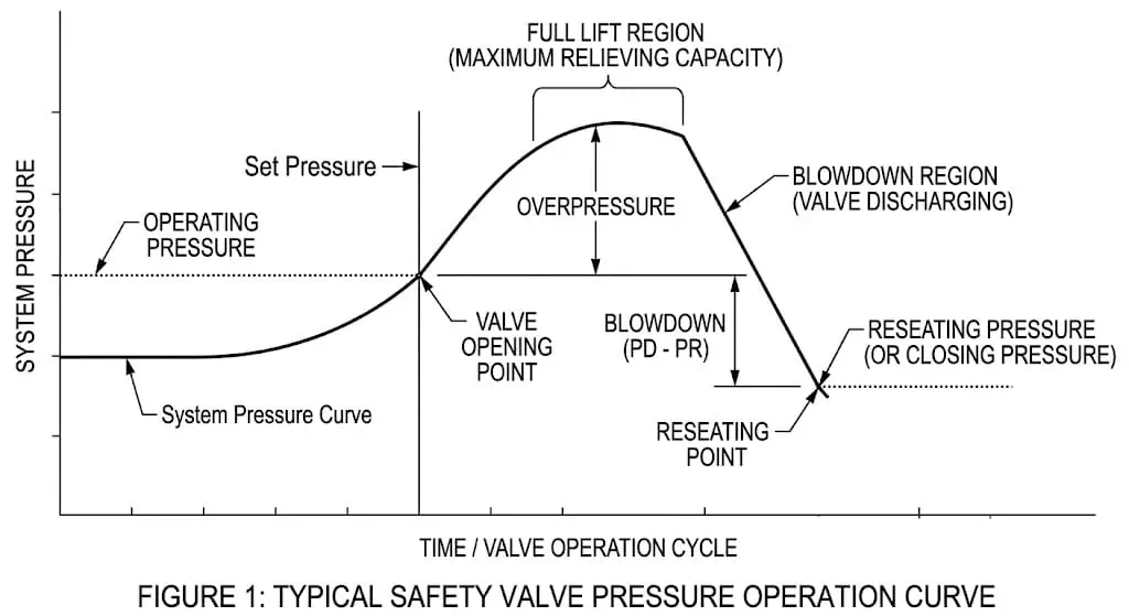
The valve releases pressure by lifting at set pressure, then reseats after pressure falls through the blowdown range. This is where several key engineering terms matter:
Set pressure: The pressure at which the valve is adjusted to begin opening. It affects when protection starts.
Overpressure: The pressure increase above set pressure during relieving. It affects the temporary pressure rise allowed during discharge.
Accumulation: The pressure increase above the protected equipment’s allowable pressure boundary during the event. It affects code acceptance.
Blowdown: The difference between opening pressure and reseating pressure. It affects when the valve closes and whether it cycles.
Back pressure: Outlet pressure acting on the valve. It affects stable lift, effective capacity, and reseating behavior.
If blowdown is wrong, if inlet pressure loss is excessive, or if discharge back pressure is ignored, the valve may reseat too late, leak repeatedly, chatter, or fail to reach stable lift. These problems usually appear after installation because shop testing does not fully reproduce plant inlet and outlet piping behavior.
Set pressure controls when the valve starts to open. Overpressure, accumulation, and blowdown determine how the valve relieves and when it can reseat without unstable cycling.
Composite field scenario for engineering training: A valve opened at the expected set pressure on test, but after installation it chattered badly in service. Investigation showed excessive inlet pressure loss from undersized inlet piping and a changed discharge path that increased built-up back pressure. The valve itself was not defective. The real system conditions were outside the stable operating boundary. The corrective action was to review inlet piping, outlet header pressure, discharge resistance, and whether a conventional, balanced bellows, or pilot-operated design was appropriate. For a deeper review, see superimposed vs built-up back pressure in safety valves.
Why Safety Valves Matter in Real Systems
Protection of People, Equipment, and Process Continuity
A safety valve protects people, equipment, and process continuity by stopping overpressure from escalating into equipment damage or a release event. In industrial systems, overpressure is rarely just a number on a gauge. It can mean vessel rupture, line failure, fire escalation, environmental release, toxic exposure, product loss, regulatory action, or long shutdown time.
Protection Function
What It Prevents
Why Users Should Care
Pressure boundary protection
Rupture of vessels, piping, and connected equipment.
Protects people and reduces repair cost.
Process continuity
Escalation from small upset to plant shutdown.
Helps keep operations stable after abnormal events.
Environmental control
Uncontrolled hydrocarbon, steam, gas, or chemical release.
Reduces regulatory, cleanup, and safety risk.
Inspection acceptance
Unapproved equipment or missing relief basis.
Supports commissioning, audit, and future repair decisions.
Safety valves must respond without human intervention.
They must meet the required code basis, test method, certification route, and documentation expectation.
They must continue performing after maintenance, repair, process modification, and repeated thermal or pressure cycling.
Preventing System Failures Before They Escalate
A safety valve limits the event before it turns into a larger system failure. That is why users should evaluate not only the valve but also the protected system. Back pressure, inlet pressure loss, poor material choice, dirty service, operation too close to set pressure, and missed recertification often create the real failure path.
Mechanically simple designs are often easier to maintain, but they still have operating boundaries.
Compact construction may reduce some installation burden, but it does not remove the need for proper sizing and piping review.
Correct maintenance prevents set pressure drift, seat damage, spring degradation, and undocumented repair risk.
In real plants, early signs such as simmer, repeated seat leakage, unstable opening, guide sticking, bellows leakage, or spring-chamber contamination should be treated as warnings, not minor nuisances. Repeated repair without finding the system cause often leads to the same failure again.
Environmental and Regulatory Importance
A safety valve supports environmental protection and regulatory compliance because overpressure failure is never only a mechanical problem. Release of flammable, toxic, sour, cryogenic, or environmentally harmful media can trigger regulatory action, production loss, and consequences beyond the failed equipment itself. The inspection record, test certificate, material traceability, and repair route are part of the safety case.
Proper relief protection reduces the chance of uncontrolled release.
Standards and certification routes help demonstrate that the valve meets the required duty.
Inspection, testing, and repair records are part of compliance, not just maintenance paperwork.
Seat tightness testing helps verify leakage performance where the applicable project or standard requires it.
Reliable safety valve performance is not just a technical requirement. It is also an inspection, documentation, and risk-management responsibility.
Where Safety Valves Are Used
Boilers and Pressure Vessels
Safety valves are widely used on boilers and pressure vessels because these systems must be protected against rapid pressure rise. Steam boilers, unfired pressure vessels, receivers, drums, heat exchangers, and many process vessels use safety valves or related pressure-relieving devices as required by the governing code. Boiler safety valves and pressure-vessel pressure relief devices may follow different code routes, so users should not mix assumptions between boiler service and pressure-vessel service.
These systems depend on the valve to open before the protected equipment exceeds its allowable pressure boundary. In this context, set pressure, code stamping, certified capacity, blowdown behavior, seat tightness, and repair traceability are more important than appearance or catalog similarity. ASME BPVC Section VIII, Division 1 provides rules for pressure vessels, while ASME boiler routes may apply where the protected equipment is a boiler.
Industrial Pipelines and Process Systems
Industrial pipelines and process systems use safety valves or related relieving devices where thermal expansion, blocked outlet, gas blowby, control failure, tube rupture, loss of cooling, or process upset can create unsafe pressure. Oil and gas, chemical, refinery, LNG/LPG, power, and energy systems often require close review of relieving scenario, required capacity, discharge route, flare header pressure, and piping effects.
Common devices used in these systems include:
Safety valves and safety relief valves for gas, vapor, steam, or mixed service.
Relief valves for liquid service.
Thermal relief valves for trapped liquid expansion in small sections of piping.
Balanced bellows or pilot-operated designs when back pressure or leakage criteria make conventional designs less suitable.
Rupture disks used alone or in combination with pressure relief valves where the project basis permits.
The main point is that users should match the device type to the actual duty instead of calling every device a safety valve by default. API 520 Part I is commonly used for sizing and selection of pressure-relieving devices in refinery and related industries, while API 520 Part II addresses installation methods for pressure-relief devices.
Everyday and Small-System Uses
Safety valves and related relieving devices also appear in smaller systems such as heaters, LPG lines, hydraulic assemblies, compressed air receivers, and packaged equipment. Even when the system is smaller, the same principles still apply: set pressure, medium compatibility, temperature range, installation orientation, outlet routing, and maintenance all matter.
Application
Why Relief Protection Is Needed
Common Checkpoint
Water heaters
Prevents pressure build-up from heating.
Correct rating, safe discharge, inspection, and replacement interval.
LPG lines
Protects against pressure rise and unsafe release.
Flammable discharge location, compatible seals, and code basis.
Pump and hydraulic assemblies
Limits pressure if downstream restriction occurs.
Liquid relief behavior, set pressure, and contamination control.
Packaged process equipment
Protects vessels, coils, and piping from internal upset.
Relieving scenario, certified capacity, and documentation.
Compressed air receivers
Protects against compressor control failure or blocked outlet.
Set pressure, receiver MAWP, capacity, and discharge routing.
Small-system relief protection should not be treated casually. Wrong material, wrong set pressure, poor discharge location, or missing test records can still create a real safety problem.
What Users Should Check Before Choosing a Safety Valve
Pressure, Set Point, and Flow Capacity
Users should verify set pressure, required relieving capacity, certified capacity, and system pressure limits before comparing suppliers or valve types. The first practical question is whether the selected valve can actually protect the equipment during the governing case. This cannot be proven by connection size alone.
Check Item
Why It Matters
Set Pressure vs MAWP
Set pressure should be established against the protected equipment limit and applicable code basis.
Required Relieving Capacity
Determines whether the valve can actually protect the system, regardless of connection size.
Certified Relieving Capacity
Shows whether the valve’s documented performance supports the required duty.
Overpressure / Accumulation Basis
Defines the allowable pressure rise during the relief event.
Back Pressure
Affects stable opening, effective capacity, blowdown, and reseating behavior.
Orifice Area / Certified Rating
More important than nozzle size alone for real protection.
Inlet Pressure Loss
Can cause chatter or unstable lift if the inlet piping is restrictive.
Correct sizing ensures the valve can handle the required flow during the governing overpressure event. A valve that only fits the line is not enough. For sizing-related project review, see the safety valve sizing and certified relieving capacity guide.
Medium, Temperature, and Material Compatibility
Selecting the right material depends on service medium, temperature, contamination level, and whether the application includes corrosive, sour, cryogenic, dirty, or polymerizing conditions. Users should look beyond body material and review nozzle, disc, spring environment, guide, bellows, gasket, and soft parts where used.
Steam and hot gas service often require high-temperature-capable trim and body materials.
Corrosive chemical service may require stainless, duplex, nickel alloy, or other corrosion-resistant materials depending on medium and temperature.
Dirty or polymerizing media can foul guides, seats, or pilot circuits.
Sour service may require NACE MR0175 / ISO 15156 review where the project requires it.
Cryogenic service may require materials and seals that retain toughness and sealing performance at low temperature.
Soft seats can improve tightness in clean service but may be unsuitable for high temperature, dirty service, or incompatible chemicals.
Tip: Material compatibility is not just about corrosion rate. It also affects leakage, sticking, spring condition, bellows life, seat tightness, and long-term repair frequency.
Installation, Testing, and Documentation
Proper installation, testing, and documentation are essential because many field failures are caused by system effects rather than by the valve body itself. Users should review the full installation and documentation route before approval. API 520 Part II is commonly used for pressure-relief-device installation review, including inlet and outlet considerations. API 527 describes seat tightness methods for conventional, bellows, and pilot-operated pressure relief valves where the project requires that test route.
Review Area
What to Confirm
Installation
Correct orientation, inlet and outlet piping, support, drainage, reaction forces, and access for testing.
Set Pressure Testing
Bench test or approved verification method with traceable records.
Seat Tightness
Appropriate leakage test route and acceptance criteria, such as API 527 where applicable.
Documents
Datasheet, sizing basis, material certificates, test records, nameplate details, calibration traceability.
Repair / Recertification Route
Whether later repair must be completed under an approved quality system such as a National Board VR repair organization when required.
Post-Maintenance Sealing
Whether the valve is recalibrated, sealed, and documented after adjustment or repair.
Users should treat documentation as part of the product, not as an afterthought. A valve that lacks set pressure records, seat tightness records, material traceability, or capacity support may be difficult to approve even if the hardware appears acceptable. A controlled safety valve RFQ datasheet helps prevent missing data at the purchase stage.
Common Problems Users Ask About
Why Does a Safety Valve Leak?
Common causes of safety valve leakage include seat damage, deposits, corrosion, wrong operating margin, back pressure effects, thermal distortion, and poor repair quality. Leakage should be treated as a symptom that requires root-cause review, not only as a seat-lapping task.
Problem
Likely Cause
Corrective Action
Seat leakage after service
Seat or disc wear, deposits, corrosion, or repeated simmer.
Poor workmanship, wrong parts, weak calibration control, or improper sealing.
Review repair records, verify test procedure, use approved repair route.
Repeated leakage in corrosive media
Wrong trim, seal material, gasket, or spring environment.
Re-evaluate material compatibility for actual medium and temperature.
Leakage during normal operation
Operating pressure too close to set pressure or unstable pressure control.
Review operating margin, blowdown, seat type, and process control behavior.
Leakage after installation
Pipe strain, dirt, poor handling, vibration, or outlet load.
Inspect installation, clean inlet, check support, and compare installed conditions with test conditions.
Users should always look for the system cause, not only the visible leak point. If the same valve leaks repeatedly after repair, the service medium, operating margin, back pressure, installation load, or material basis should be reviewed.
Why Does a Safety Valve Chatter or Open Unsteadily?
Chatter or unstable lift is usually caused by system effects such as excessive inlet pressure loss, problematic blowdown behavior, oversized selection, or increased discharge back pressure. Replacing the spring without reviewing the system often fails to solve the problem.
Factor
Explanation
What to Check
Inlet Pressure Loss
Valve sees unstable effective pressure at the inlet after opening.
Review inlet piping length, restrictions, reducers, fittings, and installation changes.
Built-up Back Pressure
Discharge resistance affects stable lift and capacity.
Check calibration, ring settings where applicable, trim condition, and duty assumptions.
Multiple Relief Loads
Shared system behavior creates unstable opening sequence.
Review staggered set points and system interaction.
Oversized Valve
Valve may lift abruptly and then lose stable flow demand.
Recheck required relieving capacity and selected orifice.
Proper piping review and correct duty selection reduce chatter risk more effectively than replacing parts repeatedly without checking the inlet and outlet system.
When Should You Repair, Re-Test, or Replace It?
Repair, re-test, or replacement should be based on defect severity, service history, inspection findings, documentation status, and whether the valve can still meet its duty. A valve should not return to service only because it has been cleaned or reseated. It must be reset, tested, documented, and sealed according to the applicable procedure.
Minor correctable damage may justify repair and full re-test.
Repeated failure, severe corrosion, damaged trim, uncertain capacity history, or missing documentation may justify replacement.
After abnormal events, fire exposure, severe chatter, or unstable operation, the valve should be reviewed before returning to service.
Users should confirm whether repair must be performed under an approved repair authorization route such as National Board VR when required by the owner or jurisdiction.
After repair, set pressure verification, seat tightness testing, documentation, and resealing should be completed before service return.
Common failure points include seat erosion, disc wear, guide sticking, spring fatigue, bellows damage, pilot circuit blockage, internal corrosion, and both internal and external leak paths.
Composite field scenario for engineering training: A valve was repaired twice for leakage, but the problem returned within months. Later review showed the process fluid had changed and was now more corrosive than the original material basis. The repeated repairs treated the symptom, not the cause. The long-term corrective action was to change trim material, verify the new service basis, update the valve records, and set a shorter inspection interval until performance history improved.
A safety valve protects systems by opening when pressure exceeds safe limits and reseating after normal conditions return. Users should focus on:
Correct selection against the real duty.
Proper installation and piping review.
Verified testing and documentation.
Inspection, repair, recalibration, and sealing traceability.
Material compatibility for body, nozzle, disc, guide, spring, bellows, and seat parts.
Decision Factor
Why It Changes the Result
Operating Pressure Margin
Too close to set pressure can increase simmer and leakage risk.
Temperature Range
Affects material behavior, spring performance, gasket behavior, and seal integrity.
Environmental and Service Conditions
Drive corrosion, fouling, freezing, vibration, and inspection frequency.
Certified Relieving Capacity
Determines whether the valve can actually protect the equipment during the governing case.
Back Pressure
Affects opening stability, effective capacity, and reseating behavior.
A clear grasp of operation, terminology, and common field issues helps users maintain safety, compliance, and system reliability.
FAQ
What is the main function of a safety valve?
A safety valve protects a pressurized system from overpressure. It opens automatically when pressure reaches the defined limit and closes again after pressure falls into the acceptable range. The real function is to prevent the protected equipment from exceeding its allowable pressure boundary while discharging enough flow for the governing overpressure case.
How often should a safety valve be tested?
There is no single universal interval for every service. Testing and inspection frequency depends on the governing code, jurisdiction, service severity, maintenance history, owner procedure, and failure history. Higher-risk, corrosive, dirty, cryogenic, sour, or high-cycle service may require shorter intervals than clean, stable duty.
Can a safety valve be used for any type of fluid?
No. Safety valve selection must match the fluid state, temperature, and material compatibility.
Fluid Type
Typical Selection Concern
Steam / Gas / Vapor
Pop-action behavior, capacity, back pressure, seat tightness.
Trim and seal compatibility, corrosion resistance.
Dirty / Fouling Service
Guide sticking, deposit formation, seat damage, pilot suitability.
Cryogenic Service
Low-temperature toughness, thermal contraction, gasket and seat behavior.
Users should match the valve and trim to the real medium, not just the process line size.
What causes a safety valve to fail?
Common causes include wrong set point assumptions, insufficient relieving capacity, corrosion, deposits, back pressure effects, poor installation, and weak repair control.
Seat or nozzle damage.
Guide sticking or pilot instability.
Incorrect material for the service.
Inlet or outlet piping effects that were not reviewed properly.
Set pressure drift after repair or undocumented adjustment.
Routine inspection and correct failure analysis help prevent recurrence.
What standards matter when buying a safety valve?
The relevant standards depend on the protected equipment and service, but several are commonly important.
ASME BPVC Section I or Section VIII for code basis and certification route.
The important point is not to list standards for appearance. It is to confirm which standard affects your actual design, sizing, installation, inspection, repair, and approval route.
What is the difference between set pressure and overpressure?
Set pressure is the pressure at which the valve is adjusted to start opening. Overpressure is the pressure increase above set pressure during relieving. Accumulation is related to the protected equipment pressure boundary, while blowdown is the pressure difference between opening and reseating. These terms must be reviewed together because they control when the valve opens, how much temporary pressure rise is allowed, and when the valve closes.
Why is certified relieving capacity more important than connection size?
Connection size only shows whether the valve can be installed. Certified relieving capacity shows whether it can actually pass the required flow during the governing overpressure case. A valve can match the inlet nozzle and pressure class but still be undersized if the orifice area or certified relieving capacity is inadequate.
How does back pressure affect safety valve performance?
Back pressure can affect opening stability, effective relieving capacity, blowdown, and reseating behavior. Superimposed back pressure exists at the outlet before the valve opens. Built-up back pressure develops after the valve opens because of discharge flow through outlet piping or headers. Excessive or variable back pressure can cause chatter, reduced capacity, poor reseating, or post-discharge leakage.
Why does a safety valve leak after installation?
Leakage after installation can come from seat damage, dirt, improper handling, operating too close to set pressure, thermal distortion, corrosion, vibration, pipe strain, back pressure, or incorrect recalibration after repair. Troubleshooting should compare shop test records with installed conditions and then review operating pressure, inlet cleanliness, outlet loads, seat material, and service history.
To provide the best experiences, we use technologies like cookies to store and/or access device information. Consenting to these technologies will allow us to process data such as browsing behavior or unique IDs on this site. Not consenting or withdrawing consent, may adversely affect certain features and functions.
Functional
Always active
The technical storage or access is strictly necessary for the legitimate purpose of enabling the use of a specific service explicitly requested by the subscriber or user, or for the sole purpose of carrying out the transmission of a communication over an electronic communications network.
Preferences
The technical storage or access is necessary for the legitimate purpose of storing preferences that are not requested by the subscriber or user.
Statistics
The technical storage or access that is used exclusively for statistical purposes.The technical storage or access that is used exclusively for anonymous statistical purposes. Without a subpoena, voluntary compliance on the part of your Internet Service Provider, or additional records from a third party, information stored or retrieved for this purpose alone cannot usually be used to identify you.
Marketing
The technical storage or access is required to create user profiles to send advertising, or to track the user on a website or across several websites for similar marketing purposes.