Safety Valve Technical Blog Superimposed vs Built-Up Back Pressure in Safety Valves Superimposed back pressure is outlet pressure already present before a safety valve opens; built-up back pressure is generated after opening as relieving flow passes through the discharge system. During an actual event, total back pressure may contain both components. The distinction affects field …

Safety Valve Technical Blog
Superimposed vs Built-Up Back Pressure in Safety Valves
Superimposed back pressure is outlet pressure already present before a safety valve opens; built-up back pressure is generated after opening as relieving flow passes through the discharge system. During an actual event, total back pressure may contain both components. The distinction affects field set-pressure review, cold differential test pressure, lift, certified or documented capacity, blowdown, reseating, valve configuration and outlet-system approval. A single unlabeled “back pressure” value is therefore not sufficient for sizing, RFQ or replacement review.
Core differenceSuperimposed pressure exists before opening; built-up pressure develops during discharge.
Main riskReporting only one generic “back pressure” value can lead to incomplete selection review.
Buyer actionSubmit outlet pressure, discharge piping, capacity and valve configuration data before quotation.
Quick Answer: Superimposed vs Built-Up Back Pressure
In safety valve selection, superimposed back pressure and built-up back pressure are not the same condition. Both occur on the outlet side of a safety valve, but they come from different sources and must be reported differently in an RFQ or replacement review.
Superimposed back pressure is the pressure that already exists at the outlet of the safety valve before the valve opens. It may come from a closed discharge header, flare system, common vent line, recovery system, downstream process pressure or another connected pressure source.
Built-up back pressure is the pressure that develops after the safety valve opens and flow passes through the outlet piping, fittings, silencers, discharge header or other restrictions. It is generated by the relieving flow itself.
This distinction matters for conventional spring loaded, bellows balanced and pilot operated safety valve review because outlet pressure can influence lift, stability, capacity, reseating behavior and configuration. The buyer should provide protected equipment, relief scenario, medium and phase, operating pressure, set pressure, required relieving capacity, relieving temperature, superimposed back pressure, built-up back pressure if known, outlet piping layout and document requirements before quotation. For a broader engineering discussion, refer to ZOBAI’s back pressure and bellows guidance.
Three Questions That Separate the Back-Pressure Terms
Does it exist before opening?
If yes, report it as superimposed back pressure and state whether it is constant or variable.
Is it generated by relieving flow?
If yes, report it as built-up back pressure and identify the outlet piping or header calculation basis.
What does the valve see during relief?
Report the total outlet pressure at the valve connection, including interacting header conditions where applicable.
A later-opening valve connected to a common header can experience pressure created by another relieving device as superimposed back pressure, because that pressure exists before the later valve opens. Once the later valve begins to discharge, its own flow and the combined header flow can add a built-up component. Shared-header studies should therefore define the sequence and simultaneous-relief assumptions rather than assigning every dynamic header pressure to one category without explanation.
Selection Boundary: What This Article Does and Does Not Decide
This article explains how to distinguish superimposed back pressure from built-up back pressure and how to prepare better RFQ information. It is not a final sizing calculation, not an API or ASME standard interpretation, not a complete installation manual and not a final valve selection document.
The page is useful when a safety valve discharges into a closed header, flare line, common vent, recovery system, scrubber, silencer or long outlet pipe where downstream pressure may affect valve performance. It is also useful when replacing an existing valve and the discharge system may have changed.
Important boundary: Do not use this article to apply a fixed allowable back pressure percentage to every valve. Acceptable back pressure depends on valve design, service medium, phase, required capacity, relieving temperature, outlet piping, manufacturer data, applicable standard version, project specification and local regulatory requirements.
Do Not Apply One Universal Back-Pressure Percentage
Catalog rules of thumb are not a substitute for the selected model’s certified or documented limits. An acceptable outlet-pressure condition depends on the valve construction, fluid, relieving pressure and temperature, required capacity, discharge coefficient basis, superimposed-pressure variability, blowdown design, outlet network and manufacturer data. A conventional, balanced-bellows and pilot-operated valve may each have different limits and correction requirements.
What the Final Engineering Decision Must Contain
| Decision Element | Required Basis | Why It Cannot Be Replaced by a Generic Percentage |
|---|---|---|
| Required relieving load | Approved governing scenario and relieving conditions | The outlet network is loaded by the actual required flow, not by connection size. |
| Valve capacity | Exact model, orifice, fluid basis and back-pressure correction | Different designs respond differently to outlet pressure. |
| Set-pressure basis | Field set pressure, constant superimposed pressure and approved CDTP procedure | A single bench setting cannot compensate for an undefined variable outlet pressure. |
| Outlet-system result | Calculation or validated model for the governing simultaneous-relief case | Pipe length, fittings, silencers, headers and downstream equipment control the result. |
| Lifecycle approval | Installation, inspection, repair and MOC records | System modifications can invalidate the original review. |
Why Back Pressure Matters in Safety Valve Selection
Back pressure is pressure acting on the outlet side of a safety valve. In a simple open discharge system, outlet pressure may be close to atmospheric pressure. In many industrial systems, however, the valve outlet may discharge into a pipe, manifold, flare header, recovery line, scrubber, silencer or closed collection system. These downstream systems can create pressure at the valve outlet.
Back pressure is important because a safety valve is not only an inlet-pressure device. The outlet condition can influence force balance, available lift, discharge flow, stability and reseating behavior. If back pressure is ignored, a valve that appears correct by set pressure and connection size may still be unsuitable for the actual installation.
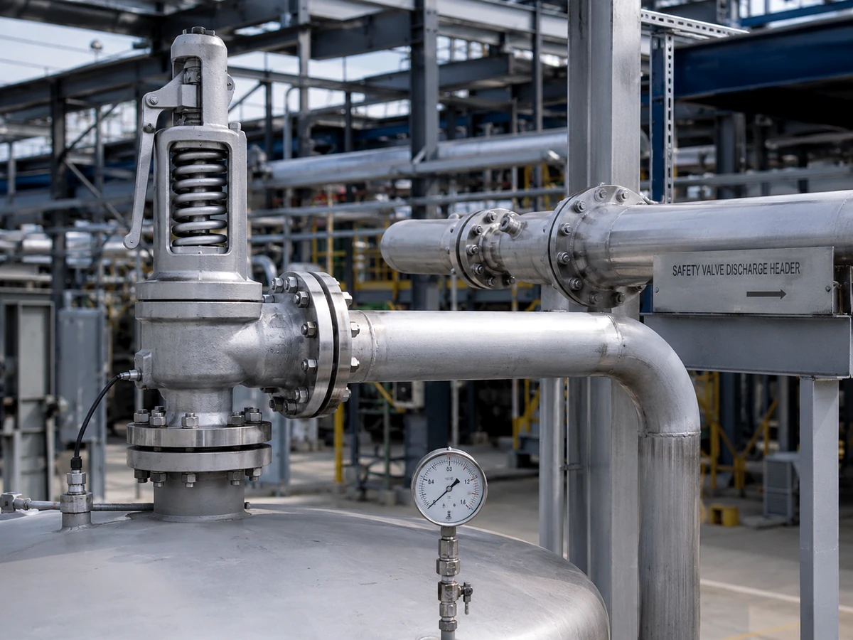
For conventional spring loaded safety valves, back pressure can be especially important because pressure on the outlet side may influence valve performance depending on valve design and service conditions. In some cases, a bellows balanced safety valve or a pilot operated safety valve may be reviewed. But the presence of back pressure does not automatically mean one configuration is correct.
Back pressure also connects to sizing and capacity review. Required relieving capacity is determined by the governing relief scenario, while built-up back pressure is related to the actual discharge flow and outlet piping arrangement. If the outlet system is not reviewed, capacity assumptions can be incomplete.
How Outlet Pressure Changes the Valve Force Balance
For a direct spring-loaded valve, outlet pressure can act on areas within the disc holder, body and bonnet-side geometry. The resulting force may change the pressure at which motion begins, the lift developed after opening and the pressure at which the valve reseats. The exact effect is design-specific; it cannot be calculated reliably from inlet and outlet connection sizes alone.
Balanced bellows are intended to reduce specified back-pressure effects on the valve force balance, but they introduce their own design limits. Bellows effective area, fatigue, corrosion, venting and failure condition must be reviewed. Pilot-operated valves use a control system to manage main-valve loading, but their response still depends on pilot exhaust, sensing pressure, downstream pressure, service cleanliness and the manufacturer’s certified configuration.
Back Pressure and Inlet Pressure Loss Can Act Together
Outlet back pressure should not be reviewed in isolation from the inlet line. Excessive inlet pressure loss can reduce pressure at the valve inlet after lift, while outlet resistance opposes or alters the relieving action. Together they can promote unstable lift, chatter, rapid cycling, reduced effective capacity and seat damage. API 520 Part II identifies installation as a separate engineering discipline and its current official page describes an Engineering Analysis for pressure-relieving-device installations.
What Is Superimposed Back Pressure?
Superimposed back pressure is pressure that exists at the outlet of the safety valve before the safety valve opens. It is “superimposed” because it is already present in the downstream system and is not created by the valve’s own relieving flow.
A common example is a safety valve connected to a discharge header that already has pressure from another process source. Another example is a valve discharging into a closed recovery system, flare line or pressurized vent system. Even before the valve lifts, the valve outlet may already see pressure.
Superimposed back pressure should be reported clearly in an RFQ. The buyer should not only say “there is back pressure.” The RFQ should state whether the pressure exists before the safety valve opens, whether it is constant or variable, and what pressure range or operating condition is expected. If this information is unknown, it should be marked as needing confirmation rather than guessed.
Constant Superimposed Back Pressure
Constant superimposed back pressure is outlet pressure that exists before valve opening and remains relatively stable for the operating condition being reviewed. For example, a safety valve may discharge into a system where the downstream pressure is controlled or normally maintained at a defined pressure.
A constant value is easier to review than a variable one, but it still affects valve selection. The supplier and engineering team need to know the outlet pressure condition when reviewing set pressure, opening behavior, capacity basis, valve configuration and documentation requirements.
Variable Superimposed Back Pressure
Variable superimposed back pressure also exists before the safety valve opens, but it changes depending on downstream system conditions. This can occur in shared discharge headers, flare systems, common vent lines or process recovery systems where pressure changes with operation, other relieving devices or downstream equipment behavior.
Variable superimposed back pressure is more difficult to evaluate because the valve may not see the same outlet pressure during every relief event. If the downstream pressure can vary significantly, the RFQ should include the expected range, normal condition, maximum condition and any project-defined basis for sizing or selection.
How Constant Superimposed Back Pressure Enters CDTP Review
When a specified constant outlet pressure is present, the approved shop setting may use a cold differential test pressure (CDTP) that accounts for the applicable back pressure and service-temperature correction. The correction must come from the valve design, manufacturer procedure, applicable code basis and project approval. It is not a universal subtraction that procurement should create independently.
The National Board’s pressure-relief-valve temperature guidance illustrates how specified back pressure and service-temperature correction can enter a CDTP example. The example is useful for understanding the concept, but the project must use the approved basis for the exact valve and service.
Why Variable Superimposed Back Pressure Is More Difficult
A single fixed shop adjustment cannot compensate for a downstream pressure that changes over the operating envelope. Variable superimposed back pressure can shift the effective opening condition and alter blowdown or reseating in a conventional design. The engineering review should define the minimum, normal and maximum pre-opening outlet pressure, its source, duration, rate of change and relationship to other relief events.
Illustrative engineering scenario: A gas vessel valve discharged to a flare header whose pressure varied with compressor recycle and other relief events. The valve passed its bench set-pressure test, but field opening and reseating were inconsistent. The cause was not a weak spring; the RFQ had listed only the normal header pressure and omitted the variable range. The corrective action was to update the flare-header study, confirm the valve configuration and issue a controlled CDTP and capacity basis. The prevention was to make minimum/normal/maximum superimposed pressure a mandatory datasheet field.
What Is Built-Up Back Pressure?
Built-up back pressure is outlet pressure that develops after the safety valve opens. It is generated by flow through the discharge system. When the valve lifts and fluid flows through outlet piping, elbows, reducers, silencers, discharge headers or other restrictions, pressure can build up at the valve outlet.
Unlike superimposed back pressure, built-up back pressure is directly related to the relieving event. It depends on flow rate, fluid properties, outlet pipe size, pipe length, fittings, discharge destination and whether the flow is steam, gas, vapor, liquid or two-phase. It may not exist before the valve opens, but it can become important during discharge.
Built-up back pressure should not be estimated from connection size alone. A short, open discharge pipe may behave differently from a long outlet line connected to a header. The same valve size can experience different built-up back pressure depending on outlet piping layout.
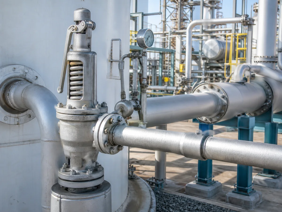
For RFQ review, the buyer should provide the outlet piping arrangement, discharge destination, pipe size, approximate length, fittings, silencer or header information, and required relieving capacity. If built-up back pressure has already been calculated by the project engineer, that value and calculation basis should be included. For broader piping context, review the safety valve installation guide.
What Creates Built-Up Back Pressure
| Outlet-System Feature | How It Raises Outlet Pressure | Required Review |
|---|---|---|
| Long or undersized discharge line | Increases frictional pressure loss at the required flow | Pipe size, length, roughness, fluid state and relieving rate |
| Elbows, reducers and fittings | Add local resistance and can change reaction forces | Fitting count, geometry and mechanical support |
| Silencer or muffler | Can add restriction, fouling and condensate retention | Vendor pressure-loss data, drainage and blockage condition |
| Common header or flare network | Combines flow from multiple sources and downstream equipment | Simultaneous-relief cases and dynamic header pressure |
| Liquid accumulation or poor drainage | Reduces effective flow area and can create hydrostatic or slug effects | Low-point drains, slope, phase behavior and startup condition |
| Downstream control or recovery equipment | Introduces additional pressure loss or pressure variation | Control-valve position, scrubber/KO-drum pressure and operating scenarios |
Common Headers and Simultaneous Relief
In a shared outlet network, the built-up pressure at one valve depends on the total flow distribution, not only on that valve’s outlet size. A fire case, utility failure or common-cause event can open several devices at once. Conversely, one valve may open after another has already raised the header pressure, creating both superimposed and built-up components for the later valve. The scenario matrix should state which devices relieve simultaneously and which downstream equipment limits the header pressure.
Illustrative Case: A Silencer Added After Commissioning
Problem: A steam safety valve began to chatter after a silencer was installed to reduce noise. Cause: The silencer pressure loss and condensate drainage were not included in the original outlet calculation, increasing built-up back pressure during lift. Action: The team measured the discharge condition, checked the seat and guide for damage, recalculated the outlet system and revised the silencer/drain arrangement. Prevention: Any silencer, weather hood, diffuser or discharge modification must be controlled through management of change before return to service.
Superimposed vs Built-Up Back Pressure: Key Differences
The most practical way to separate the two terms is to ask: does the pressure exist before the safety valve opens, or is it generated after the valve opens due to flow?
| Comparison Point | Superimposed Back Pressure | Built-Up Back Pressure |
|---|---|---|
| When it exists | Before the safety valve opens | After the safety valve opens |
| Main source | Existing outlet, header, flare, vent, recovery or downstream system pressure | Pressure generated by discharge flow through outlet piping or restrictions |
| Related to relief flow? | Not necessarily | Yes |
| Can be constant or variable? | Yes, it can be constant or variable | Usually tied to the relieving event and discharge flow |
| Main RFQ data needed | Existing downstream pressure condition and whether it is constant or variable | Outlet piping layout, discharge route and required relieving capacity |
| Typical engineering concern | Opening behavior, set pressure review, valve configuration and outlet pressure effect | Capacity, lift, stability, outlet piping design and discharge restriction |
| Common mistake | Reporting one “back pressure” value without explaining the source | Ignoring outlet pipe length, fittings, header pressure or discharge restriction |
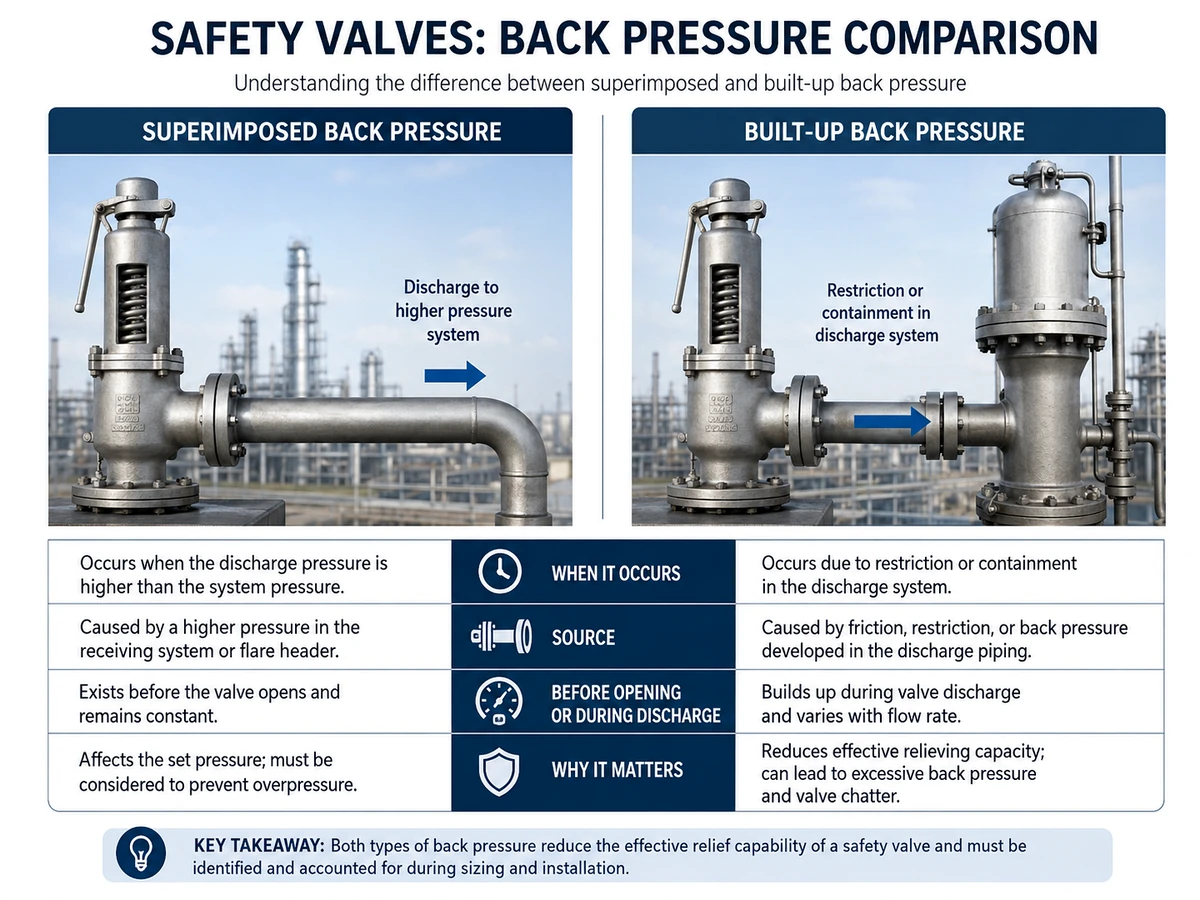
Total back pressure may include both superimposed and built-up components, depending on system design and relief conditions. For example, a valve may discharge into a header that already has pressure before opening, and additional pressure may develop during relief because the discharge flow passes through the same header. In that case, both conditions should be reviewed.
Total Back Pressure During the Governing Event
Total back pressure is the outlet pressure acting at the valve during the relieving event. Depending on the system, it can include an existing superimposed component plus a built-up component generated by the valve and the connected network. The total value should be reported at the valve outlet reference point and at the governing relief time, not as an unrelated downstream equipment pressure.
Data-location warning: Flare-header pressure at a distant node, scrubber operating pressure and pressure at the valve outlet are not automatically the same. State the calculation node, elevation, flow case and whether pressure is gauge or absolute.
What Every Back-Pressure Number Should State
- Type: superimposed, built-up or total.
- Timing: before opening, during own relief, or during a simultaneous event.
- Variation: constant, minimum/normal/maximum, transient or scenario-specific.
- Reference point: valve outlet flange/thread, header node or downstream equipment.
- Pressure basis: gauge or absolute.
- Source: measured, calculated, manufacturer assumption or preliminary estimate.
- Approval status: confirmed, preliminary or to be confirmed.
Back Pressure Data Hierarchy: What the RFQ Should Actually Separate
Many RFQs fail because the buyer provides only one line, such as “back pressure exists” or one approximate back pressure value without defining the source. That is not enough for engineering review. A better RFQ separates the type of outlet pressure, when it occurs, how it varies and what data supports it.
| Data Item | What to Confirm | Why It Matters |
|---|---|---|
| Superimposed back pressure | Existing outlet pressure before valve opening; constant or variable | May affect opening behavior, set pressure review and valve configuration |
| Built-up back pressure | Pressure generated during discharge due to flow through outlet piping and restrictions | May affect capacity, lift, stability and outlet piping review |
| Total back pressure | Whether total outlet pressure includes both superimposed and built-up components | Prevents underestimating the outlet pressure condition during relief |
| Relief scenario | Blocked outlet, fire case, regulator failure, thermal expansion, tube rupture or other case | Defines required relieving capacity and discharge flow condition |
| Medium and phase | Steam, gas, vapor, liquid or two-phase service | Affects sizing, discharge behavior, valve response and material review |
| Outlet system | Atmosphere, header, flare, scrubber, recovery line, silencer or closed system | Defines whether outlet pressure is open, restricted, shared or variable |
If any of these inputs are unknown, mark them as “to be confirmed.” Do not convert missing outlet-system information into a final valve selection assumption.
Measurement, Calculation and Assumption Are Different Evidence Levels
| Evidence Status | Acceptable RFQ Wording | Engineering Use |
|---|---|---|
| Approved calculation | “Maximum superimposed back pressure: X, approved flare study reference…” | Can support formal selection when the scenario and node match. |
| Measured operating data | “Normal header pressure measured at node…; relief-event maximum not yet confirmed.” | Useful for operating context but may not cover the governing relief event. |
| Existing datasheet value | “Existing value for reference; system changes not yet revalidated.” | Identity/reference only until current system conditions are confirmed. |
| Preliminary assumption | “Budget quotation assumption; engineering confirmation required.” | Supports conditional quotation, not final PO release. |
| Unknown | “To be confirmed; outlet drawing attached.” | Triggers a technical hold point and a missing-data request. |
Who Owns Each Back-Pressure Input?
| Data | Typical Responsible Function | Supplier Review Role |
|---|---|---|
| Governing relief scenario and required flow | Process / relief-system engineering | Check completeness and use the approved input |
| Header pressure and outlet network | Process, flare-system or piping engineering | Confirm the selected valve is reviewed against the stated condition |
| Valve back-pressure limits and correction factors | Valve manufacturer / application engineer | Provide model-specific documented limits |
| CDTP and test procedure | Manufacturer / approved repair organization / responsible engineer | Issue an order-specific setting basis |
| PO document and inspection scope | Procurement / QA / inspection | Confirm inclusion and traceability before order release |
How Each Type of Back Pressure Affects Valve Configuration
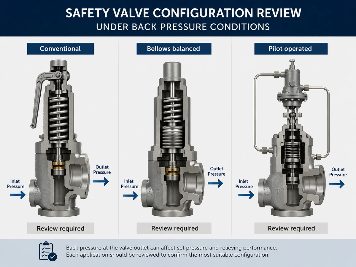
Back pressure can affect valve configuration, but it does not automatically determine the correct valve type. The same back pressure value may have different consequences depending on the valve design, service medium, set pressure, operating pressure, temperature, required capacity and manufacturer limits.
For some applications, buyers may also review back pressure balanced safety valves, especially when outlet pressure influence is a key part of the RFQ. However, this still does not replace project-specific sizing, service review or manufacturer data confirmation.
| Configuration | When It May Be Reviewed | Critical Checks Before Selection |
|---|---|---|
| Conventional safety valve | Simple outlet arrangement, acceptable back pressure conditions and manufacturer-approved service limits | Set pressure, operating margin, capacity, outlet pressure effect, stability and discharge piping |
| Bellows balanced safety valve | Back pressure may influence conventional valve performance and project conditions allow bellows use | Bellows material, temperature, corrosion, fatigue, bonnet venting, inspection access and failure consequence |
| Pilot operated safety valve | Service requires review of operating margin, seat tightness, pressure behavior or special configuration | Medium cleanliness, sensing line, tubing, freezing or plugging risk, maintenance and project acceptance |
Configuration caution: Back pressure does not automatically require a bellows balanced or pilot operated valve. The final configuration must be reviewed against service data, manufacturer limits, project specification and applicable standard requirements.
Conventional Spring-Loaded Valves
A conventional valve may be acceptable when the stated back pressure is within the exact model’s approved limits and the outlet condition does not produce unacceptable set-pressure shift, capacity reduction, chatter or reseating behavior. Constant superimposed pressure may be addressed through an approved setting basis in some designs; variable pressure and high built-up pressure require deeper review.
Balanced-Bellows Valves
A balanced bellows can reduce specified back-pressure effects on the force balance, but it does not make the valve independent of the discharge system. Capacity correction, bellows pressure/temperature rating, fatigue, corrosion, bonnet venting and failure consequences remain relevant. The bonnet vent must not be blocked, plugged or connected to a pressure source unless the exact design permits it.
The National Board’s improper-repair guidance notes that bellows damage can allow system back pressure to act where the design intended isolation. This is why bellows condition and vent status are return-to-service checks, not optional maintenance details.
Pilot-Operated Valves
Pilot-operated valves may provide useful operating-margin and back-pressure characteristics in appropriate service, but the pilot system must be reviewed as part of the pressure path. Main-valve outlet pressure, pilot exhaust destination, sensing-line routing, dome pressure, condensation, freezing, fouling and simultaneous header events can affect response. “Pilot operated” is not proof of unlimited back-pressure capability.
Illustrative Case: Bellows Vent Blocked During Repainting
Problem: A balanced-bellows valve showed inconsistent opening after maintenance. Cause: The bonnet vent had been painted over and the bellows condition was not verified, so the assumed pressure balance was no longer reliable. Action: The vent was restored, the bellows and internal parts were inspected, and the valve was retested under the approved procedure. Prevention: Add bonnet-vent status and bellows integrity to inspection and coating work packs.
Back Pressure and Required Relieving Capacity
Back pressure is not only an installation detail. It can affect safety valve capacity review and performance verification.
Required relieving capacity is determined by the governing relief scenario. A blocked outlet case, fire case, regulator failure, thermal expansion event, tube rupture or other scenario may require different relieving loads. Built-up back pressure is related to the flow created during that relieving event. Therefore, the required flow rate and outlet system must be considered together.
For relief scenario and discharge system review, buyers may compare the project basis with ZOBAI’s API 521 pressure relief systems guidance. This can help separate relief-case thinking from valve-only replacement thinking.
For example, if a safety valve relieves a large vapor flow into a long discharge line, built-up back pressure may be different from a small thermal relief case with short outlet piping. Similarly, steam, gas, vapor, liquid and two-phase flow can create different discharge behavior. The outlet system should be reviewed according to the actual medium and relief case.
| Item | Not Enough | Better RFQ Input |
|---|---|---|
| Valve size | Only inlet and outlet connection size | Required relieving capacity, selected orifice or model basis, medium, phase and relieving condition |
| Back pressure | One generic back pressure value | Superimposed, built-up and total back pressure distinction with constant/variable condition |
| Outlet piping | “Discharge pipe exists” | Pipe size, length, fittings, elbows, silencers, header, discharge destination and support condition |
| Capacity basis | Assuming connection size proves capacity | Relief scenario, required flow, calculation basis and manufacturer capacity data where applicable |
Connection size alone does not prove capacity. A valve with the same inlet size may not have the same orifice, lift, certified capacity or documented capacity basis. Outlet size alone also does not prove acceptable built-up back pressure. The selected valve must be checked against manufacturer data and the applicable sizing basis. For more context, review ZOBAI’s guide to safety valve sizing and certified relieving capacity and the API 520 safety valve sizing reference page.
Capacity Correction Is Model-, Fluid- and Configuration-Specific
Back pressure can change the usable capacity basis, but the correction is not one universal factor. The selected model, fluid, pressure ratio, relieving temperature, orifice, lift characteristic, conventional/bellows/pilot configuration and certification basis determine which manufacturer or code-supported correction applies. The technical offer should show the uncorrected basis, the applicable correction and the resulting supported capacity.
API 520 Part I, currently identified by API as the 10th edition, addresses sizing and selection in its applicable refinery scope. API 521 addresses pressure-relieving and depressuring-system design in its stated LNG, petrochemical, gas-plant and petroleum-production scope. Neither source makes connection size a substitute for an approved relief load and outlet-system study.
Required Capacity and the Outlet Network Must Be Solved Together
The governing scenario establishes the required flow, and that flow establishes the outlet-network pressure loss. If the outlet pressure then changes the valve’s supported capacity, the review may require iteration: required load → tentative valve/orifice → outlet-network pressure → corrected valve capacity → final confirmation. A quotation that assumes zero back pressure while the project uses a closed header is incomplete.
Two-Phase, Flashing and Condensing Service Need Additional Review
Two-phase or flashing flow can change density, momentum, pressure loss and reaction force along the outlet line. Steam discharge can condense in poorly drained piping, and wet gas can form liquid holdup. In these services, the RFQ should state the approved sizing method, phase behavior, outlet-system assumptions and drainage philosophy rather than apply a dry-gas back-pressure estimate.
| Approval Step | Evidence | Technical Hold Point |
|---|---|---|
| Required load | Approved scenario calculation | No final selection without a defined governing case |
| Selected valve/orifice | Exact model and configuration | No substitution by inlet/outlet size alone |
| Outlet pressure | Superimposed and built-up calculation | No generic “back pressure” line |
| Corrected capacity | Manufacturer/certification-supported basis | Must meet required load at stated conditions |
| Installed stability | Inlet and outlet engineering review | Capacity evidence does not prove piping stability |
What Buyers Should Send in an RFQ
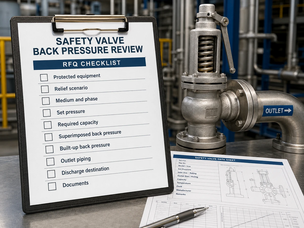
A clear RFQ helps the supplier and engineering team distinguish between superimposed and built-up back pressure. It also reduces the risk of selecting the wrong valve configuration or missing an important outlet system condition. For a full inquiry package, use the safety valve RFQ datasheet guide.
| RFQ Item | Why It Matters |
|---|---|
| Protected equipment | Defines the pressure protection function |
| Relief scenario | Determines required relieving capacity |
| Medium and phase | Affects sizing, valve behavior and discharge flow |
| Operating pressure | Helps review margin below set pressure |
| Set pressure | Defines the valve opening point |
| Required relieving capacity | Needed for sizing and capacity review |
| Relieving temperature | Affects material, bellows, trim, gasket and rating review |
| Superimposed back pressure | Defines outlet pressure before the valve opens |
| Constant or variable condition | Helps review outlet pressure variation and valve configuration |
| Built-up back pressure | Defines outlet pressure created during discharge flow |
| Outlet piping layout | Affects built-up back pressure and mechanical loads |
| Discharge destination | Atmosphere, header, flare, scrubber, recovery line or other system |
| Valve type preference | Conventional, bellows balanced or pilot operated review |
| Material / seat / seal | Affects corrosion, leakage, temperature and service compatibility |
| Required documents | Datasheet, calibration record, capacity basis, test record and inspection scope |
| Replacement data | Existing nameplate, photos, old datasheet and installation condition |
If some values are unknown, they should not be invented. The RFQ can mark them as “to be confirmed,” but the buyer should understand that final selection cannot be completed without enough service and installation data.
Technical Hold Points Before Purchase-Order Release
| Hold Point | Minimum Approval Evidence | Reason to Stop Release |
|---|---|---|
| Back-pressure classification | Superimposed, built-up and total values clearly separated | A generic value can lead to the wrong configuration or CDTP |
| Variation and scenario | Constant/variable range and simultaneous-relief basis | Normal header pressure may not cover the governing event |
| Valve capability | Exact model, configuration, correction and supported capacity | Product family claims do not prove order-specific performance |
| Outlet network | Drawing/calculation including silencers, headers and restrictions | Built-up pressure cannot be approved from outlet size alone |
| Test setting | Field set pressure and approved CDTP basis | Bench setting may be wrong when constant back pressure exists |
| Documents and deviations | Datasheet, calculations, tests, inspection scope and open deviations | Unresolved assumptions can reappear at commissioning |
Minimum Outlet-System Attachment Set
- Marked-up P&ID showing the protected equipment and discharge destination.
- Outlet isometric or layout with sizes, lengths, fittings, elevation and supports.
- Flare/header study excerpt or approved node pressures for the governing cases.
- Silencer, diffuser, scrubber or downstream equipment pressure-loss data.
- Simultaneous-relief case list and operating pressure range.
- Existing valve datasheet, nameplate, previous back-pressure basis and installation photos for replacement work.
Replacement Verification Workflow for Existing Safety Valves
Back pressure problems often appear during replacement projects because the old valve is copied by connection size, set pressure or appearance. A safer replacement review should confirm whether the outlet system and relief case are still the same as the original design basis.
Collect existing valve dataRecord nameplate data, set pressure, connection, material, old datasheet, service medium and installation photos.
Check outlet system changesConfirm whether outlet pipe length, header pressure, discharge destination, silencer or flare connection has changed.
Separate back pressure typesIdentify superimposed pressure before opening and built-up pressure during discharge if known.
Confirm relief scenario and capacityDo not rely on connection size alone. Confirm required relieving capacity and calculation basis where available.
Review configurationEvaluate whether conventional, bellows balanced or pilot operated design is suitable for the current service.
Confirm documents before orderDefine datasheet, set pressure test, capacity basis, material records and inspection requirements before purchase.
Management-of-Change Triggers
The original back-pressure review should be reopened when any of the following changes occur:
- New relief devices are connected to the common header.
- Process throughput, compressor capacity, heat input or required relieving load increases.
- Flare, scrubber, recovery-system or downstream operating pressure changes.
- Outlet pipe size, length, routing, support, silencer, diffuser or isolation arrangement changes.
- The valve changes from conventional to bellows/pilot, or vice versa.
- The fluid phase, relieving temperature or two-phase assumption changes.
- Repeated chatter, abnormal blowdown, seat damage or post-lift leakage is found.
Return-to-Service Evidence After Repair or Replacement
| Evidence | Required Check | What It Does Not Replace |
|---|---|---|
| As-found report | Opening point, leakage, deposits, bellows/guide condition and seal status | Root-cause analysis of the outlet system |
| As-left set-pressure/CDTP report | Approved shop setting and test conditions | Built-up back-pressure calculation |
| Seat-tightness result | Closing leakage under the stated test | Capacity and field stability |
| Bellows/pilot inspection | Integrity, vent/exhaust, sensing and replaced components | Manufacturer back-pressure limits |
| Installation release | Outlet support, drainage, orientation, open isolation path and header connection | Relief-scenario calculation |
| MOC closeout | Updated datasheet, P&ID, calculation and equipment register | Future periodic inspection |
Documents and Testing to Confirm Before Order
For back pressure applications, document scope should be confirmed before order placement. The required package depends on the project specification, valve type, inspection plan and applicable regulatory basis. For lifecycle controls, review the safety valve maintenance and inspection guide.
| Document / Check | What It Supports | When to Confirm |
|---|---|---|
| Valve datasheet | Model, set pressure, connection, material, valve type and service data | Before quotation and again before order confirmation |
| Back pressure basis | Superimposed, built-up and total back pressure assumptions | Before final valve configuration review |
| Capacity basis | Required relieving capacity and selected valve capacity reference where applicable | Before final selection |
| Set pressure test record | Opening pressure adjustment and test basis | Before shipment or inspection release where required |
| Seat tightness requirement | Leakage expectation under specified test conditions | Before order if the project requires a specific leakage test |
| Material record | Body, trim, spring, bellows or pressure-retaining material traceability where required | Before order if specified by the project |
| Inspection scope | Witness test, third-party inspection, visual inspection or document review requirements | Before order placement |
Do not assume every document or test is included by default. State the required document scope in the RFQ so the supplier can review feasibility, schedule impact and inspection requirements before order confirmation.
What Each Test or Document Actually Proves
| Evidence | It Can Support | It Cannot Prove by Itself |
|---|---|---|
| Set-pressure / CDTP report | Opening adjustment under stated shop conditions | Capacity, built-up back pressure or field stability |
| API 527 seat-tightness report | Closed-seat leakage under the applicable test method | Required relieving capacity or outlet-network adequacy |
| Capacity listing / manufacturer data | Supported flow for the exact design and stated conditions | Correct process scenario or installed pipework |
| Outlet-system calculation | Predicted superimposed/built-up pressure for the modeled case | Valve mechanical condition or seat tightness |
| Bellows or pilot functional inspection | Condition of pressure-balancing/control components | Unlimited back-pressure tolerance |
| As-found / as-left records | Condition trend and post-repair setting | Closure of process and piping root causes |
API 527 describes seat-tightness methods for applicable metal- and soft-seated pressure relief valves, including conventional, bellows and pilot-operated designs. A leakage result should not be presented as evidence that the valve has adequate capacity or acceptable back-pressure performance.
Tag and Serial-Number Traceability
The final package should link the protected-equipment tag, safety-valve tag, manufacturer, model, serial number, orifice/configuration, field set pressure, CDTP, capacity evidence, back-pressure basis, test reports and installation release. This prevents a correct calculation from being attached to a different physical valve during shutdown replacement.
Technical References for Further Review
The following official sources support different parts of the engineering review. They are not interchangeable, and the project-required edition remains controlling.
API 520 Part I — Sizing and Selection
API’s official page identifies the 10th edition and describes sizing procedures used to specify pressure-relieving devices in the standard’s applicable refinery scope.
Review API 520 Part I
API 520 Part II — Installation
API’s official page identifies the 7th edition and notes an Engineering Analysis for appropriate pressure-relieving-device installation.
Review API 520 Part II
API 521 — Relief and Depressuring Systems
Supports pressure-relieving and depressuring-system design in the stated LNG, petrochemical, gas-plant and petroleum-production scope.
Review API 521
ASME BPVC Section XIII — Overpressure Protection
Provides rules for overpressure protection of pressurized equipment and requirements addressing pressure-relief-device design, materials, inspection, assembly, testing and marking.
Review ASME Section XIII
ISO 4126-1 — Safety Valve Product Requirements
Provides general product requirements for safety valves. It is a product standard and does not replace the project’s application, sizing or outlet-system design.
Review ISO 4126-1
ISO 4126-4 — Pilot-Operated Safety Valves
Provides product requirements for pilot-operated safety valves; service cleanliness and outlet-system suitability remain application decisions.
Review ISO 4126-4
API 527 — Seat Tightness
Supports seat-tightness testing for applicable pressure relief valves. It does not certify required capacity or back-pressure stability.
Review API 527
National Board — Temperature, Back Pressure and CDTP Example
Illustrates how specified back pressure and temperature correction can enter a cold differential test pressure example.
Review National Board guidance
National Board — PRD Inspection Guide
Highlights discharge-piping support and consideration of devices designed for anticipated back-pressure conditions.
Review the PRD inspection guide
National Board — Bellows Repair Risk
Explains why damaged bellows can allow back pressure to influence areas that the design intended to balance.
Review improper-repair guidanceStandards and Evidence Boundary
| Source | Supports | Does Not Replace |
|---|---|---|
| API 520 Part I | Sizing and selection in its applicable scope | Relief-scenario definition and outlet-network model |
| API 520 Part II | Installation engineering | Correct valve capacity and mechanical condition |
| API 521 | Relief/depressuring-system analysis in its applicable industries | Product certification for the selected valve |
| ASME Section XIII | Overpressure-protection and device requirements | Project-specific RFQ and manufacturer limits |
| ISO 4126-1 / -4 | Safety-valve and pilot-operated product requirements | Application design and flare/header analysis |
| API 527 | Seat-tightness test basis | Capacity, CDTP and back-pressure approval |
| National Board technical guidance | Inspection/repair concepts and examples | Controlling code edition and owner approval |
Standards limitation: Use the edition adopted by the project, jurisdiction and owner. Official overview pages and technical articles help establish scope, but they do not reproduce the purchased standard or authorize an unverified capacity, configuration or repair claim.
Common Mistakes When Reporting Back Pressure
Using one generic value
Report whether the value is superimposed, built-up or total back pressure. If superimposed back pressure is variable, state that variation.
Ignoring shared headers
A shared discharge header may already have pressure before valve opening, and that pressure may change during operation.
Ignoring outlet piping
Built-up back pressure is related to discharge flow through outlet piping, fittings, silencers and discharge restrictions.
Assuming bellows always solves it
Bellows balanced valves may help in some conditions, but bellows limits and service compatibility must be checked.
Replacing by appearance
If outlet piping or downstream pressure has changed, the old valve selection may no longer be valid.
Confusing pressure terms
Set pressure, relieving pressure, accumulation and back pressure are different engineering terms and should not be merged.
Illustrative Case: Header Expansion Without Revalidation
Problem: A conventional valve that had operated acceptably began cycling after several new users were connected to the flare header. Cause: The original review used the former header pressure and did not include the new simultaneous-relief combinations. Action: The flare network and valve capacity were revalidated, and damaged seating parts were inspected. Prevention: Connecting a new PRD or changing flare operating pressure must trigger an MOC review for every affected valve.
Illustrative Case: Bench Test Passed but Field Behavior Failed
Problem: A valve passed set-pressure and seat-tightness tests but chattered during a plant upset. Cause: The test bench did not reproduce the installed inlet loss and outlet built-up back pressure. Action: The team reviewed both piping sides, corrected the outlet restriction and reassessed the selected orifice. Prevention: Treat bench tests as component evidence, not proof that the installed relief system is stable.
Ask ZOBAI for Safety Valve Back Pressure Review
Ask ZOBAI for back pressure review when the safety valve discharges to a closed header, flare line, common vent, recovery system, scrubber, silencer or any outlet system that may create pressure at the valve outlet. Review is also important when the back pressure is variable, when the service is steam, gas, vapor, liquid or two-phase, or when an existing valve is being replaced after piping changes.
Before requesting a final model or quotation, send the protected equipment, relief scenario, medium and phase, operating pressure, set pressure, required relieving capacity, relieving temperature, superimposed back pressure, built-up back pressure if known, outlet piping layout, discharge destination, material requirements and required documents.
- Superimposed back pressure value or range
- Built-up back pressure or outlet piping data
- Relief scenario and required relieving capacity
- Medium, phase and relieving temperature
- Discharge destination and header condition
- Valve type, material and document requirements
ZOBAI can help identify whether the RFQ data is complete enough to discuss conventional, bellows balanced, back pressure balanced or pilot operated configurations. Final safety valve selection still depends on real operating conditions, manufacturer data, applicable standard version, project specification and local regulatory requirements.
FAQ
What is superimposed back pressure in a safety valve?
Superimposed back pressure is pressure already present at the valve outlet before that valve opens. It can come from a flare header, common vent, recovery system, downstream process pressure or another device already discharging.
What is built-up back pressure?
Built-up back pressure is outlet pressure generated after the valve opens as relieving flow passes through discharge piping, fittings, silencers, headers and downstream restrictions.
Can total back pressure include both superimposed and built-up back pressure?
Yes. Total back pressure during a relief event can include an existing superimposed component plus a built-up component created by the valve and the connected discharge network.
Does back pressure always require a bellows balanced safety valve?
No. The correct configuration depends on the back-pressure type and range, fluid, required capacity, temperature, manufacturer limits and project requirements. A conventional or pilot-operated design may also be appropriate in defined conditions.
What should I include in an RFQ if back pressure exists?
State superimposed, built-up and total back pressure separately; identify constant or variable behavior, reference point, gauge/absolute basis, relief scenario, required flow, outlet layout and data status.
Can I replace a safety valve without checking back pressure?
It is not recommended. Replacement may proceed only when documented interchangeability and unchanged system conditions have been confirmed. Header, silencer, process-load or discharge-routing changes require a new review.
What is constant superimposed back pressure?
It is pre-opening outlet pressure that remains reasonably stable for the reviewed operating condition. It still must be included in the approved set-pressure, CDTP, capacity and configuration basis.
What is variable superimposed back pressure?
It is pre-opening outlet pressure that changes with downstream operations or other relief events. A single fixed bench adjustment may not compensate for the full range, so the minimum, normal and maximum values should be provided.
Does a balanced bellows eliminate all back-pressure effects?
No. Bellows designs reduce specified force-balance effects, but capacity correction, bellows rating, fatigue, corrosion, bonnet venting and bellows-failure behavior still require review.
Can a pilot-operated safety valve handle any back pressure?
No. Pilot exhaust, sensing-line routing, dome pressure, service cleanliness, condensation, freezing and the exact certified configuration determine the acceptable outlet-pressure conditions.
How does back pressure affect relieving capacity?
Depending on the valve design and fluid, back pressure can alter lift or require a model-specific capacity correction. The corrected supported capacity must still meet the approved required relieving load.
Can connection size prove acceptable built-up back pressure?
No. Outlet size alone does not define pressure loss. The review needs the required flow, fluid properties, pipe layout, fittings, discharge destination and simultaneous-header conditions.
What should be checked in a common flare or vent header?
Check normal and maximum header pressure, simultaneous-relief scenarios, valve opening sequence, downstream equipment limits, node pressure at each valve outlet and the resulting corrected valve capacity.
Does passing API 527 prove acceptable back-pressure performance?
No. API 527 addresses seat tightness for applicable pressure relief valves. It does not prove required capacity, CDTP, outlet-system adequacy or stable field operation.
What should be checked after repairing a balanced-bellows valve?
Verify bellows integrity, bonnet vent condition, replaced parts, set-pressure/CDTP basis, seat tightness, serial traceability and whether the original back-pressure assumptions remain valid.
What changes should trigger management of change for a relief outlet system?
New header users, higher throughput, new simultaneous scenarios, different flare or recovery pressure, outlet-pipe or silencer changes, fluid-phase changes and repeated chatter or leakage should trigger revalidation.