Oil Industry Application Selection Guide Safety Valve Selection Guide for Oil Industry Systems Oil industry safety valve selection starts with the protected pressure boundary and the governing overpressure scenario—not with flange size, pressure class, or an old valve model. The review must connect required relieving capacity, fluid phase at relieving conditions, set pressure and allowable …

Oil Industry Application Selection Guide
Safety Valve Selection Guide for Oil Industry Systems
Oil industry safety valve selection starts with the protected pressure boundary and the governing overpressure scenario—not with flange size, pressure class, or an old valve model. The review must connect required relieving capacity, fluid phase at relieving conditions, set pressure and allowable accumulation, back pressure and flare-header behavior, inlet/outlet piping, component materials, code route, inspection evidence, and the future repair pathway. This guide is written for refinery, petrochemical, upstream production, gas-processing, pipeline, skid, EPC, procurement, inspection, and maintenance teams.
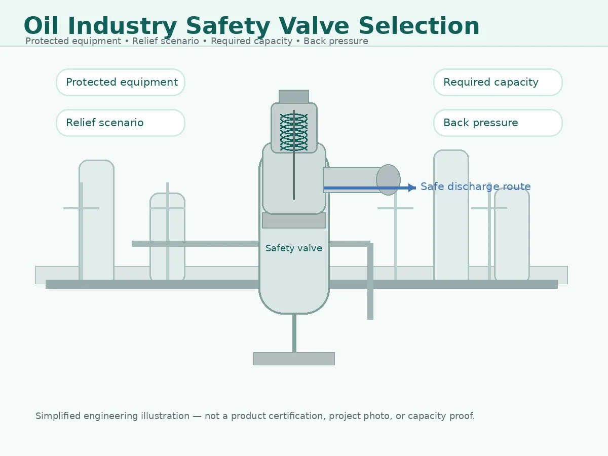
Simplified engineering illustration; not a project photo, certification proof or certified capacity statement.
Quick Answer: How Should Oil Industry Safety Valve Selection Start?
Start with the protected equipment and the governing relief scenario. Then establish the fluid and phase at relieving conditions, operating pressure, MAWP or design pressure, set pressure, allowable overpressure or accumulation, required relieving capacity, relieving temperature, superimposed and built-up back pressure, inlet and outlet piping, component materials, certification route, and required inspection documents.
The main selection error is treating connection size, flange class, body material, or an old nameplate as proof of suitability. Those items help identify the mechanical interface, but they do not prove the current relief scenario, selected orifice, certified capacity, fluid basis, back-pressure tolerance, or code acceptance.
For a broader workflow, buyers can review ZOBAI’s safety valve selection guide, while this article focuses on oil industry and refinery RFQ data.
Practical decision rule: a quotation can be preliminary while some project data remain open, but a purchase order should not be released until the relief duty, exact valve configuration, supported capacity, installation limits, materials, deviations, tests, and required documents are technically approved.
Selection Boundary: What This Page Helps You Decide
This Guide Helps With
- Preparing refinery safety valve RFQ data.
- Separating pressure terms before selection.
- Checking required capacity versus connection size.
- Identifying back pressure and piping questions.
- Screening service, material and replacement risks.
This Guide Does Not Replace
- Formal relief calculation.
- Project code or local regulatory review.
- Manufacturer-certified or documented capacity data.
- Flare or discharge system design.
- Final approval by the responsible engineer.
Define the Oil Industry Segment and Equipment Boundary
“Oil industry” is not one uniform application. Upstream production, gas treatment, pipelines, LNG, terminals, refinery process units, petrochemical plants, and low-pressure storage systems can use different equipment codes, relief scenarios, materials rules, discharge systems, and inspection routes. The RFQ should identify the plant segment and the exact pressure boundary being protected.
| Plant Segment | Typical Protected Equipment | Selection Boundary to Confirm |
|---|---|---|
| Upstream production / gas treatment | Separators, compressors, wellsite skids, gas treatment vessels | Production-fluid composition, H2S, solids, low temperature, isolation philosophy, discharge destination, and jurisdiction |
| Midstream / pipeline / terminal | Compressor stations, pump stations, metering skids, pig traps, transfer equipment | Blocked-in sections, thermal expansion, station upset, line-pack, blowdown, vibration, and remote maintenance |
| Refinery / petrochemical | Columns, drums, reactors, exchangers, compressors, process vessels | API 520/521 project basis, flare network, fire case, reaction or utility failures, refinery sour service, and inspection program |
| Atmospheric or low-pressure storage | Storage tanks and low-pressure vessels | Do not assume a spring-loaded pressure relief valve is the correct venting device; confirm the tank code, normal and emergency venting basis, and pressure/vacuum limits |
Use a Three-Layer Approval Chain
A reliable selection separates three approvals: the process duty, the valve capability, and the order-specific evidence. A supplier quotation cannot create the governing relief scenario, and a process calculation cannot prove that the quoted valve model has the required certified capacity.
| Approval Layer | Primary Question | Typical Evidence |
|---|---|---|
| Process / equipment basis | Why can pressure rise, and how much flow must be relieved? | Equipment datasheet, P&ID, relief calculation, process simulation, fire or tube-rupture basis |
| Valve application capability | Can the exact design, orifice, materials, and configuration protect that duty? | Manufacturer datasheet, capacity listing, back-pressure limits, material specification, installation limits |
| Order and lifecycle evidence | Does the supplied valve match the approved configuration and remain traceable? | Approved drawing, nameplate, test reports, material records, inspection release, repair and calibration history |
Selection Starts With the Relief Scenario, Not the Valve Size
A refinery pressure relief valve is installed to protect equipment from overpressure. The valve size is a result of relief calculation and manufacturer data review; it is not the starting point. Two valves with the same inlet and outlet connection can have different orifice areas, capacity coefficients, trim designs, allowable back pressure limits and material restrictions.
An RFQ that only says “DN50 × DN80 safety valve, 10 bar set pressure” is incomplete. ZOBAI still needs to know what equipment is being protected, what event causes overpressure, what fluid is being relieved, what the required relieving rate is and what discharge system the valve will connect to.
Selection Inputs Should Be Marked by Data Status
For EPC and procurement review, each critical field should be marked as confirmed, preliminary, inherited from an existing valve, or still unknown. This prevents an old nameplate or budget assumption from becoming an unintentional design basis.
| Data Status | Recommended Wording | Permitted Use |
|---|---|---|
| Confirmed | From approved calculation / equipment datasheet | Formal technical review |
| Preliminary | For budget quotation; final confirmation required | Conditional model and commercial review only |
| Existing reference | From old nameplate or historical file; not revalidated | Identification and gap analysis |
| Unknown | To be confirmed / calculation pending | Technical hold point |
Where Are Safety Valves Used in Oil Industry Systems?
Safety valves and pressure relief valves may be used across many oil industry systems, including process vessels, separators, heat exchangers, columns, reactors, compressors, pumps, pipelines, storage-related systems and modular skids. The valve’s purpose is not simply to release pressure; it is to protect specific equipment against a defined overpressure case.
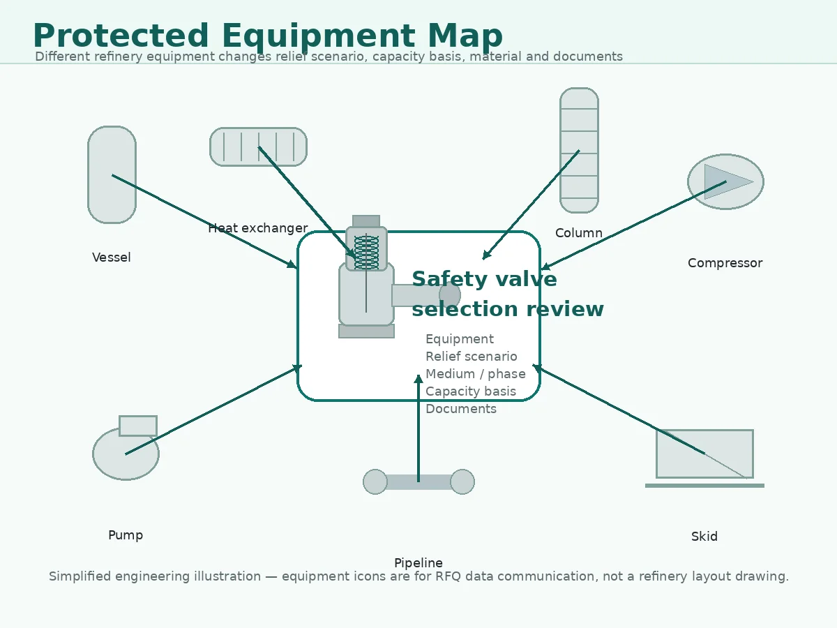
Conceptual refinery equipment map for selection communication; not a refinery layout drawing.
Refinery Selection Matrix
| Protected Equipment / System | Typical Relief Question | Selection Data Needed |
|---|---|---|
| Pressure vessel or separator | Fire case, blocked outlet, vapor or two-phase relief | MAWP, set pressure, required capacity, medium, relieving temperature, discharge basis |
| Heat exchanger | Tube rupture, blocked outlet or thermal expansion | High-pressure side, low-pressure side, fluid data, pressure limits and transient assumptions |
| Process column | Vapor relief, fire exposure or overhead system restriction | Relief scenario, vapor load, back pressure, discharge header and material requirements |
| Reactor or process vessel | Reaction upset, gas generation, heating imbalance | Reaction basis, gas generation data, temperature, materials and required documents |
| Pump discharge line | Blocked discharge or liquid thermal expansion | Liquid properties, blocked outlet pressure source, small-capacity relief requirement |
| Compressor discharge system | Gas overpressure, pulsation or discharge header interaction | Gas properties, pressure range, required flow, back pressure and stability review |
| Oil and gas skid | Compact layout, replacement or package specification | Datasheet, layout, inlet/outlet piping, connection standard, documents and inspection scope |
Why Equipment Type Changes the Selection Data
Different equipment types generate different selection questions. A heat exchanger may require tube rupture review. A vessel may require fire case review. A pump discharge system may require blocked outlet or thermal expansion review. A column connected to a flare or discharge header may require careful back pressure review.
Atmospheric and Low-Pressure Tanks Need a Different Venting Review
Oil terminals and refineries also contain atmospheric and low-pressure tanks. These systems may require pressure/vacuum vents, emergency vents, conservation vents, or other devices under a tank-specific venting basis rather than a conventional pressure-vessel safety valve. The protected equipment code and allowable pressure range must be identified before a device family is selected.
Scope warning: do not treat every tank nozzle marked “vent” or “relief” as a pressure-vessel safety-valve application. Confirm the tank design code, maximum allowable pressure and vacuum, normal breathing, filling/emptying, thermal effects, and emergency exposure case.
Define the Relief Scenario Before Selecting the Valve
The relief scenario is the event that causes the protected equipment to exceed its allowable pressure. In oil industry systems, the relief scenario is the foundation for sizing and selection. Without it, the valve request is only a mechanical description, not an engineering specification.
Common oil industry relief scenarios include blocked outlet, external fire exposure, thermal expansion, control valve failure, regulator failure, tube rupture, utility failure, compressor discharge overpressure and two-phase or flashing relief.
| Relief Scenario | What Must Be Confirmed | Selection Risk If Missing |
|---|---|---|
| Blocked outlet | Maximum upstream pressure source, flow path, medium and required relieving rate | Valve may be undersized or selected for the wrong flow basis |
| Fire exposure | Wetted surface, fluid response, relieving temperature and discharge system basis | Temperature, capacity and material requirements may be wrong |
| Thermal expansion | Trapped liquid volume, heat input, pressure rise and small-capacity relief requirement | Valve may be oversized or may not suit liquid expansion duty |
| Control valve or regulator failure | Failure position, upstream pressure, downstream equipment rating and relief capacity basis | Protected equipment may not be reviewed against maximum supply pressure |
| Heat exchanger tube rupture | High-pressure side, low-pressure side, fluid properties and transient assumptions | Transient flow, phase behavior and pressure limits may be misread |
| Two-phase or flashing relief | Fluid data, relieving condition, method basis and manufacturer review | Single-phase assumptions may be unsafe or incomplete |
For relief system context, API 521 is commonly associated with pressure-relieving and depressuring system review. Buyers can read ZOBAI’s API 521 pressure relief systems guide for a dedicated overview.
Scenario Ownership and Calculation Evidence
The governing scenario should be approved by the responsible process or equipment engineer. A valve supplier may identify missing data or review a stated duty, but should not silently select a fire case, blocked outlet, tube rupture, or reaction scenario on behalf of the plant.
| Scenario Input | Typical Responsible Function | Evidence Before PO Release |
|---|---|---|
| Protected equipment and allowable pressure boundary | Mechanical / equipment engineering | Equipment datasheet, code basis, MAWP or design pressure |
| Credible overpressure scenarios | Process engineering / process safety | Relief study, HAZOP action, design basis, approved calculation |
| Required relieving load and phase | Process engineering | Calculation with fluid properties and relieving conditions |
| Flare or disposal-system pressure | Process / flare-system engineering | Hydraulic model, simultaneous-relief case, node pressure |
| Valve model and supported capacity | Valve application engineering | Manufacturer data and project-accepted capacity evidence |
Fire Case, Tube Rupture, and Two-Phase Boundaries
These cases require more than a label on the RFQ. A fire case depends on the applicable wetted-area, heat-input, fluid-response, and depressuring assumptions. Tube rupture depends on the high- and low-pressure systems, transient flow, upstream inventory, and whether full rupture is credible. Flashing or two-phase relief requires an approved method and reliable thermodynamic data. API Standard 521 provides official pressure-relieving and depressuring-system guidance for the petroleum, petrochemical, LNG, gas-plant, and related facilities within its scope, but it does not replace the project calculation. Review API Standard 521 official information.
Illustrative engineering scenario: a heat-exchanger relief valve was initially quoted from the low-pressure-side nozzle size and the existing set pressure. The later tube-rupture review showed a much larger transient inflow and a different phase condition. The correction was to approve the scenario and required load first, then reselect the valve and discharge system. The prevention is to treat tube rupture as a process calculation, not a nameplate replacement exercise.
Confirm Pressure Terms: Operating Pressure, MAWP, Set Pressure and Overpressure
Pressure terms are often confused in safety valve inquiries. For refinery applications, this confusion can lead to wrong set pressure, insufficient operating margin or incorrect sizing assumptions.
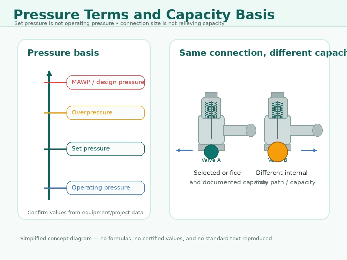
Simplified concept diagram; no calculated capacity values or certified relieving capacities are shown.
| Term | Meaning in Selection | Why It Matters |
|---|---|---|
| Operating pressure | Normal process pressure | Helps check margin below set pressure |
| Maximum operating pressure | Highest expected operating condition | Helps prevent simmer, leakage or nuisance opening |
| Design pressure / MAWP | Pressure limit of protected equipment | Sets the protection boundary and code basis |
| Set pressure | Valve opening setting | Must be compatible with equipment protection requirements |
| Overpressure / accumulation | Pressure increase during relieving | Affects relieving pressure and capacity basis |
| Blowdown / reseating pressure | Valve closing behavior after discharge | Important for process recovery and leakage risk |
Set Pressure Is Not the Same as Operating Pressure
A valve set pressure should not be selected simply by copying the normal operating pressure. There must be enough operating margin to avoid simmering, leakage or frequent opening. At the same time, the set pressure must protect the equipment within the allowed pressure basis.
MAWP / Design Pressure Must Be Confirmed Against the Protected Equipment
MAWP or design pressure should come from the protected equipment documentation. It should not be inferred from flange class alone. Before quotation, send the equipment datasheet or the confirmed MAWP / design pressure together with the proposed set pressure.
Relieving Pressure, Accumulation, and CDTP Must Be Separated
Relieving pressure is the pressure used with the relieving condition for capacity evaluation. Accumulation is referenced to the protected equipment pressure boundary during the event. Cold differential test pressure (CDTP) is a shop-test setting that may account for specified service temperature and constant superimposed back pressure for the exact valve design and approved procedure. CDTP is not a universal field correction that procurement should calculate independently.
| Pressure Record | What It Supports | What It Does Not Prove Alone |
|---|---|---|
| Equipment MAWP / design-pressure record | Protected pressure boundary | Correct valve capacity or installation |
| Approved set-pressure basis | Required field opening setting | Shop CDTP or full relieving capacity |
| CDTP instruction | Approved shop-test correction for the specified valve and service basis | Variable back-pressure suitability or system stability |
| As-left set-pressure record | Final bench setting under stated test conditions | Correct relief scenario, capacity, or flare-node pressure |
Separate Required Relieving Capacity From Connection Size
Required relieving capacity is one of the most important selection inputs. It is not the same as nominal size. A valve with a larger flange does not automatically have enough documented or certified capacity, and a smaller connection does not automatically mean inadequate capacity.
For detailed capacity concepts, see ZOBAI’s safety valve sizing and certified relieving capacity guide. For standard-related sizing context, see the API 520 safety valve sizing guide.
| Capacity Item | What It Means | What the Buyer Should Send |
|---|---|---|
| Required relieving capacity | The flow rate required to protect the equipment under the governing case | Mass flow or volumetric flow, fluid phase, calculation basis and governing scenario |
| Required area | The calculated flow area needed for the relief case | Calculation output, standard basis and fluid properties where available |
| Selected orifice / valve design | The manufacturer’s selected internal flow path and valve configuration | Datasheet, model boundary and manufacturer review requirement |
| Documented or certified capacity | Capacity supported by manufacturer data and applicable documentation | Required document scope, inspection requirement and project specification |
| Connection size | Mechanical inlet and outlet fit-up | Flange or thread standard, rating, facing and installation layout |
Do not select by connection size alone. Connection size affects installation fit-up, but capacity depends on relief duty, fluid properties, relieving pressure and temperature, orifice, valve design and manufacturer data.
Use a Capacity Approval Chain
The selected valve should be approved through a traceable chain rather than by nominal size:
Governing relief load → required flow area → selected model and orifice → documented or certified capacity → back-pressure correction → installed-system verification.
API 520 Part I, 10th Edition is the official API sizing-and-selection reference for pressure-relieving devices in refineries within its scope. It supports the sizing and selection process; it does not create the process relief scenario or prove that a quotation matches the project.
The Capacity Fluid Basis Must Match the Service
| Capacity Claim | Required Cross-Check | Common Error |
|---|---|---|
| Air / gas capacity | Gas composition, molecular weight, compressibility, pressure, temperature, and back pressure | Applying an air value directly to hot process gas |
| Steam capacity | Saturated or superheated condition, relieving pressure, temperature, and code basis | Using steam capacity for hydrocarbon vapor |
| Liquid capacity | Density, viscosity, vapor pressure, flashing, and back pressure | Using gas-certified capacity for liquid duty |
| Two-phase capacity | Approved method, phase behavior, inlet condition, and manufacturer acceptance | Applying single-phase coefficients |
Illustrative engineering scenario: a same-size replacement valve had the correct set pressure but a smaller effective orifice. The plant had increased throughput since the original installation. The error was detected only when the blocked-outlet load was recalculated. The correction was to select a larger supported orifice and recheck the outlet header. The prevention is to revalidate capacity after debottlenecking or throughput change.
Check Medium, Phase, Temperature and Material Limits
Oil industry services may involve hydrocarbon vapor, gas, liquid, steam, hot oil, flashing liquid, sour gas, corrosive components, dirty fluids, waxy fluids or polymerizing media. Medium and phase influence sizing, trim selection, seat leakage expectations, material compatibility, maintenance frequency and discharge design.
| Medium / Phase | Selection Concern | Confirmation Needed |
|---|---|---|
| Clean gas or vapor | Capacity basis, set pressure, back pressure and discharge header | Gas properties, pressure, temperature and discharge condition |
| Hydrocarbon vapor | Fire case, discharge system, material and documentation review | Relief scenario, composition, relieving temperature and document scope |
| Liquid | Thermal expansion, liquid relief method, stability and discharge containment | Liquid properties, trapped volume, pressure source and outlet routing |
| Flashing liquid or two-phase flow | Calculation basis, relieving condition and manufacturer review | Fluid data, phase behavior, calculation method and project acceptance |
| Sour or corrosive service | Body, trim, spring, bellows, gasket and seal material review | Fluid composition, concentration, temperature and project material specification |
| High-temperature oil or vapor | Pressure-temperature rating, spring, seat, gasket and thermal expansion review | Relieving temperature, material rating, bonnet design and seat requirement |
| Dirty, waxy or polymerizing media | Sticking, leakage, plugging, maintenance and material review | Cleanliness, solids, viscosity, maintenance interval and service history |
Material Grade Alone Does Not Prove Service Suitability
A material name such as WCB, CF8M, stainless steel or alloy steel is not enough to prove suitability. The selected body, bonnet, nozzle, disc, guide, spring, bellows, gasket and seat must match the service condition and project specification.
If the service is corrosive, sour, dirty, high-temperature or polymerizing, the RFQ should identify the service condition clearly instead of asking only for a material grade.
Sour Service Is Not One Universal Material Specification
“NACE material” is not a complete RFQ requirement. The applicable sour-service document depends on the plant segment and environment. ISO 15156-1:2020 addresses materials for H2S-containing environments in oil and gas production and natural-gas treatment. Refinery and related processing environments may instead use the project-specified ISO 17945 / NACE MR0103 route for resistance to sulfide stress cracking. Neither document replaces corrosion review for pitting, chloride cracking, high-temperature sulfidation, naphthenic-acid corrosion, erosion, or non-metallic seal compatibility.
Material boundary: state the actual H2S partial pressure, water phase, chloride, pH, temperature, hardness, heat treatment, welding condition, and project material class where applicable. A generic “sour service” note is not enough to approve every component.
Review Materials by Component and Failure Mode
| Component | Oil-Industry Failure Concern | RFQ / Approval Check |
|---|---|---|
| Body and bonnet | Pressure-temperature rating, general corrosion, sulfidation, external exposure | Material grade, heat treatment, rating basis, coating and traceability |
| Nozzle, disc, and seat | Erosion, deposits, pitting, galling, leakage | Wetted trim material, hardness, seat type, surface condition |
| Guide and spindle | Fouling, wax, polymer, corrosion products, misalignment | Clearance, material pairing, cleanliness, maintenance access |
| Spring | High-temperature relaxation, atmospheric corrosion, H2S exposure | Spring material, temperature basis, bonnet environment, range |
| Bellows | Fatigue, corrosion, pinhole leakage, blocked bonnet vent | Material, pressure-temperature limit, vent arrangement, inspection method |
| Soft seats and gaskets | Swelling, hardening, extrusion, decompression damage | Elastomer/polymer compatibility, temperature, pressure cycling, fire requirement |
Illustrative engineering scenario: a refinery RFQ specified only “NACE compliant stainless steel.” Technical review found that the service was wet H2S in downstream refining, while the supplier had assumed an upstream ISO 15156 material basis. The correction was to define the project sour-service standard, component scope, hardness, heat treatment, and material certificates. The prevention is to name the applicable document and service environment rather than use “NACE” as a generic adjective.
Review Back Pressure, Discharge Header and Valve Configuration
Back pressure is a major selection issue in refinery pressure relief systems. It can come from a discharge header, flare system, vent line, long outlet piping or other connected relief devices. It may be constant or variable. It may exist before the valve opens, or it may be generated during relieving.

Simplified discharge and back pressure illustration; not a construction drawing or certified discharge system design.
Back pressure can affect capacity, opening behavior, stability and leakage. Therefore, the valve type should not be selected by name alone. For a deeper engineering explanation, review ZOBAI’s back pressure and bellows guide.
| Valve Configuration | When It May Be Considered | Data Still Required |
|---|---|---|
| Conventional spring-loaded valve | Simple discharge arrangements with acceptable back pressure | Back pressure, operating margin, set pressure, medium and capacity |
| Balanced bellows safety valve | Applications where back pressure influence must be reviewed | Bellows material, bonnet venting, back pressure type, temperature and corrosion |
| Pilot-operated safety valve | Certain high-pressure or tight operating margin applications | Pilot compatibility, sensing line, cleanliness, medium, maintenance and project acceptance |
Selection boundary: A bellows or pilot-operated design should not be treated as an automatic solution. The amount and type of back pressure, fluid, temperature, corrosion, venting, maintenance and project acceptance must be reviewed.
Common Flare Headers Require Simultaneous-Relief Review
A flare-connected valve may see superimposed pressure before opening and additional built-up pressure after flow enters the header. The relevant outlet pressure is the node pressure for the governing relief combination, not merely the normal flare-header pressure. The review should identify coincident relief devices, common-cause events, flare-system operating cases, and whether the back pressure is constant or variable.
| Flare / Header Input | Why It Matters | Required Evidence |
|---|---|---|
| Normal and maximum header pressure | Defines superimposed pressure range | Operating data and flare study |
| Simultaneous-relief combination | Controls total header flow and node pressure | Approved relief-load summary |
| Valve outlet node pressure | Used for configuration and capacity review | Hydraulic model output |
| Outlet pipe, elbows, reducers, silencers | Generate local built-up back pressure | Isometric or line list and hydraulic calculation |
| Liquid knockout and drainage | Liquid head or accumulation can add outlet pressure and vibration | Layout, elevation, drainage and operating review |
Valve Configuration Boundaries
A conventional valve may be acceptable only within its model-specific back-pressure and stability limits. A balanced bellows can reduce the specified effect of outlet pressure on the spring-loaded mechanism, but it does not remove all capacity correction, fatigue, corrosion, venting, or failure considerations. A pilot-operated valve also requires review of pilot exhaust, sensing-line routing, dome pressure, fouling, condensation, freezing, and service cleanliness.
API 520 Part II, 7th Edition addresses installation and includes an engineering-analysis route for pressure-relieving-device installations within its refinery scope.
Illustrative engineering scenario: a conventional valve began chattering after a new unit was connected to the same flare header. The valve itself had not changed. The new simultaneous-relief combination raised the outlet node pressure and altered the inlet/outlet pressure balance. The correction was to update the flare model, capacity correction, valve configuration, and outlet piping review. The prevention is to trigger MOC whenever flare users or header operating pressure change.
Confirm Connection Standard, Inlet Loss and Outlet Piping
Mechanical connection data is necessary, but it is not enough by itself. Buyers should confirm inlet size, outlet size, flange standard and dimensions, pressure class, facing, material, gasket requirement and installation layout.
For high-temperature or refinery services, the selected connection and body material should also be checked against pressure-temperature ratings, not only nominal flange class.
Inlet and outlet piping can also affect safety valve performance. Excessive inlet pressure loss may contribute to chatter or instability. Unsupported outlet piping can impose mechanical loads on the valve body. For a deeper installation review, see the safety valve installation guide.
| Piping / Installation Item | What to Check | Risk If Ignored |
|---|---|---|
| Inlet piping | Short, direct routing where possible; pressure loss review | Chatter, instability or reduced capacity margin |
| Inlet connection | Size, flange standard, rating and gasket requirement | Fit-up error or pressure-temperature rating mismatch |
| Outlet piping | Discharge destination, back pressure, support and reaction force | Mechanical load, vibration or unsafe discharge |
| Drainage | Avoid liquid accumulation where applicable | Corrosion, freezing, blockage or outlet restriction |
| Bonnet vent | Especially important for bellows balanced designs | Back pressure compensation may be compromised |
| Support | Heavy outlet piping should not be carried by the valve body | Body stress, flange leakage or misalignment |
| Discharge safety | Avoid discharge toward personnel, walkways or unsafe areas | Personnel hazard and unsafe plant layout |
Inlet and Outlet System Checks Must Be Combined
High inlet pressure loss and high outlet back pressure can act together. After the valve opens, inlet pressure at the nozzle may fall while outlet pressure rises. The combined condition can reduce effective lift and cause chatter, rapid cycling, capacity loss, seat damage, or post-relief leakage.
| Installation Check | Engineering Question | Evidence |
|---|---|---|
| Inlet branch | Is the route short and free of avoidable restrictions, pockets, and closed isolation valves? | P&ID, isometric, pressure-loss calculation |
| Outlet hydraulic resistance | What built-up back pressure occurs at required flow? | Outlet calculation or flare model |
| Piping loads and thermal movement | Does the valve carry pipe weight, reaction, or thermal strain? | Support layout and stress review |
| Drainage and low points | Can condensate or liquid accumulate? | Elevation, drains, heat tracing, operating review |
| Bellows bonnet vent / pilot exhaust | Is the functional vent path open and safely routed? | GA drawing, installation inspection |
Changes That Require MOC and Revalidation
- Process throughput, feed composition, operating pressure, or heat input changes.
- New control-valve capacity, pump, compressor, utility source, or upstream pressure source.
- Flare-header users, normal header pressure, knockout drum, silencer, or outlet piping changes.
- Insulation, heat tracing, drainage, weather hood, or discharge routing changes.
- Valve model, orifice, bellows, pilot system, seat type, or material substitution.
- Repeated chatter, leakage, corrosion, failed as-found test, or unexplained set-pressure drift.
Replacement in Oil Industry Systems Requires More Than Nameplate Matching
Maintenance teams often need to replace a refinery safety valve because of leakage, corrosion, failed testing, obsolete model, damaged trim or shutdown planning. Replacement should not be based only on visual similarity, flange size or set pressure.
What to Check on the Existing Valve
- Nameplate photo and tag number.
- Manufacturer and model if visible.
- Inlet and outlet size.
- Set pressure and capacity marking if available.
- Body and trim material.
- Service medium and installation photos.
- Last calibration or test record.
When Engineering Review Is Needed
Engineering review is needed when the service has changed, the required capacity is unknown, the old valve has leaked or chattered, the discharge system has changed, the material is uncertain or the original documentation is incomplete.
Replacement Verification Workflow
| Step | Check | Do Not Assume |
|---|---|---|
| 1. Identify the old valve | Tag, nameplate, model, set pressure, inlet/outlet size and material | That the old valve was correctly selected for current duty |
| 2. Confirm the protected equipment | Equipment datasheet, MAWP/design pressure and service condition | That flange class equals equipment pressure limit |
| 3. Recheck the relief scenario | Blocked outlet, fire, thermal expansion, tube rupture or other case | That the original scenario still governs |
| 4. Verify capacity basis | Required relieving capacity, capacity marking or old calculation | That same size means same capacity |
| 5. Review installation condition | Inlet loss, outlet support, discharge route and back pressure | That leakage or chatter is only a valve defect |
An Old Nameplate Is Identification Evidence, Not Current Design Basis
The old nameplate can identify manufacturer, model, set pressure, connection, and marking. It cannot prove that the original valve was correctly selected, that the process has not changed, that the current required capacity is unchanged, or that the discharge header remains within the original basis.
Return-to-Service Evidence Chain
| Stage | Minimum Check | Release Evidence |
|---|---|---|
| As-found | Set pressure, leakage, seal status, deposits, corrosion, bellows/pilot condition | As-found report and photos |
| Repair / replacement | Parts, spring range, seat geometry, material and model configuration | Repair traveler or supplier build record |
| As-left testing | Set pressure/CDTP, seat tightness, functional checks, required pressure tests | Signed test reports |
| Installation | Correct tag, orientation, inlet cleanliness, outlet support, vents, drains, isolation status | Installation checklist |
| Engineering closure | Relief scenario, capacity, flare/back pressure, MOC and deviations closed | Responsible engineer approval |
For applicable ASME/NBIC service, the National Board VR Certificate of Authorization supports an authorized pressure-relief-valve repair quality system. It does not replace the current relief calculation, installed-system review, or owner acceptance.
RFQ Data Checklist for Oil Industry Safety Valve Review
A complete RFQ helps ZOBAI review the application faster and reduces the risk of quoting the wrong configuration. The buyer does not need to have every calculation completed before contacting ZOBAI, but missing data should be clearly identified.
Minimum RFQ Data Before Engineering Review
If the full datasheet is not ready, start with these five items before requesting a preliminary oil industry safety valve review:
- Protected equipment: vessel, heat exchanger, pump discharge line, compressor system, pipeline section, skid or other equipment.
- Relief scenario: fire case, blocked outlet, thermal expansion, tube rupture, regulator failure, control failure or other confirmed case.
- Pressure basis: operating pressure, MAWP / design pressure, proposed set pressure and allowable overpressure basis.
- Required capacity: required relieving rate, fluid phase and calculation basis if available.
- Back pressure / discharge: superimposed back pressure, built-up back pressure, discharge header, flare / vent connection or outlet routing.
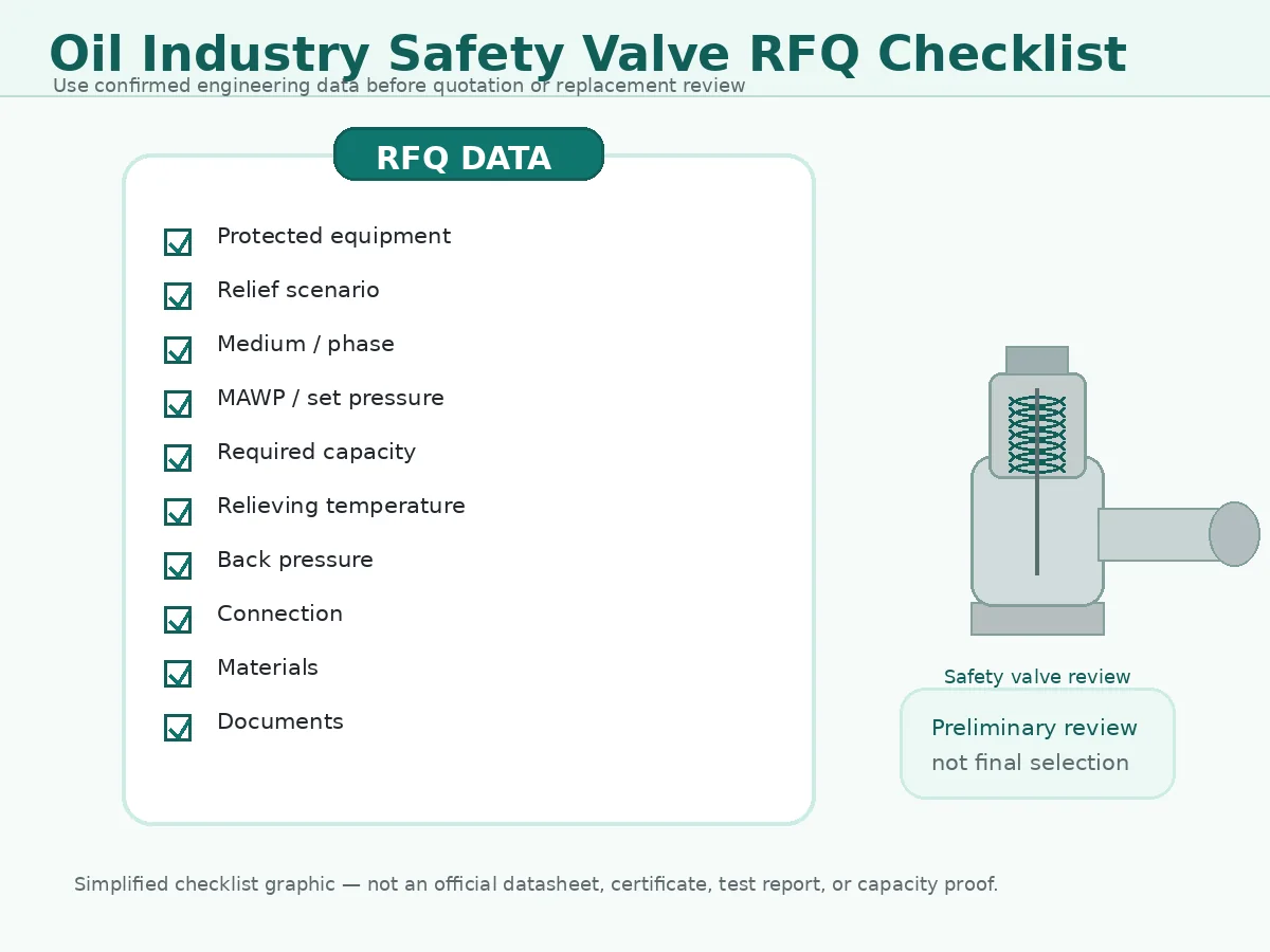
RFQ preparation graphic; not an official datasheet, certificate, test report or capacity proof.
| RFQ Data | Required Detail | Status to Mark If Missing |
|---|---|---|
| Protected equipment | Vessel, heat exchanger, line, pump, compressor, skid or other equipment | Need user confirmation |
| Relief scenario | Fire, blocked outlet, thermal expansion, tube rupture, regulator failure or other case | Need process / project confirmation |
| Medium and phase | Gas, vapor, liquid, flashing liquid, two-phase or other condition | Need fluid confirmation |
| Pressure data | Operating pressure, MAWP / design pressure and proposed set pressure | Need datasheet or project basis |
| Required relieving capacity | Required rate and calculation basis, if available | Need sizing basis |
| Relieving temperature | Temperature during relief, not only normal operating temperature | Need relieving condition |
| Back pressure | Superimposed and built-up; constant or variable | Need discharge review |
| Connection | Inlet / outlet size, flange standard, rating and facing | Need mechanical interface data |
| Material requirements | Body, trim, seat, spring, bellows and gasket where specified | Need service/material specification |
| Documents required | Datasheet, drawing, test report, material certificate and capacity basis | Need procurement / inspection scope |
RFQ Completeness Check
If protected equipment, relief scenario, pressure basis and required capacity are all missing, the inquiry is not ready for final valve selection. It can still be sent for preliminary discussion, but the missing items should be clearly marked as to be confirmed.
PO Technical Hold Points
| Hold Point | Must Be Approved Before Unconditional PO Release |
|---|---|
| Duty basis | Protected equipment, governing scenario, required load, fluid phase, relieving pressure and temperature |
| Pressure basis | MAWP/design pressure, set pressure, allowable overpressure/accumulation, operating margin, CDTP where applicable |
| Exact valve capability | Manufacturer, model, orifice, configuration, supported capacity and correction factors |
| Back pressure and installation | Superimposed/built-up pressure, flare node, inlet loss, outlet piping, support, drains and vents |
| Component materials | Body, trim, guide, spring, bellows/pilot parts, soft seat, gasket, sour-service and temperature basis |
| Documents and deviations | Approved datasheet, GA, nameplate, capacity evidence, tests, MTCs, ITP and closed deviation list |
RFQ Responsibility Matrix
| Information | Buyer / EPC Responsibility | Supplier Responsibility |
|---|---|---|
| Relief scenario and required capacity | Provide or identify as pending responsible-engineer approval | Review stated basis; do not invent the process case |
| Valve selection | Approve application requirements and deviations | Propose exact model, orifice, configuration and limitations |
| Materials | Define process environment and project material rules | Identify component materials and exceptions |
| Documentation | Define required certificates, tests, witness points and format | Confirm inclusion, scope, timing and traceability |
| Installation | Provide piping and flare/back-pressure data | State model-specific installation limits |
What This Guide Does Not Replace
This guide is intended to help oil industry buyers prepare better selection and RFQ data. It does not replace formal relief calculation, process hazard review, code interpretation, flare system analysis, manufacturer capacity data or final approval by the responsible engineer.
Final valve selection depends on actual protected equipment, confirmed relief scenario, medium and phase, operating pressure and MAWP, set pressure, required relieving capacity, relieving temperature, back pressure, inlet and outlet piping, selected valve model, manufacturer data, applicable standard version, project specification and local regulatory requirements.
Standards and Reference Notes
Technical References for Standards Context
Oil-industry safety valve selection usually requires several documents with different roles. Standards are evidence and control frameworks; they do not replace the project relief scenario, fluid data, flare analysis, or exact manufacturer capacity evidence.
| Official Source | Primary Role | Important Boundary |
|---|---|---|
| API 520 Part I | Sizing and selection of pressure-relieving devices in refineries within its scope | Does not define the process scenario or approve a supplier quotation by itself |
| API 520 Part II | Installation and engineering analysis for pressure-relieving-device installations | Does not correct an undersized valve or missing flare-system data |
| API Standard 521 | Pressure-relieving and depressuring-system guidance for covered petroleum, petrochemical, gas, and LNG facilities | Does not replace the project-specific relief and flare calculations |
| ASME BPVC Section VIII, Division 1 | Pressure-vessel construction and overpressure-protection context | Must be applied with the adopted edition, jurisdiction, and project requirements |
| ASME BPVC Section XIII | Rules for overpressure protection and pressure-relief-device design, material, inspection, assembly, testing, and marking | Does not determine the plant relief load or flare-node pressure |
| API 527 | Seat-tightness test methods and acceptance for applicable PRVs | Seat leakage acceptance is not capacity certification |
| ISO 4126-1 | General product requirements for safety valves | It is a product standard, not a complete application-design standard |
| ISO 15156-1 | General material-selection principles for H2S-containing oil/gas production and natural-gas treatment environments | Not automatically the correct refinery/downstream sour-service specification |
| ISO 17945 / NACE MR0103 | SSC-resistant metallic materials for corrosive petroleum-refining and related processing environments | Does not cover every corrosion or non-metallic failure mechanism |
| National Board NB-18 | Searchable manufacturer, assembler, and certified-device information | Manufacturer listing does not prove every model or quoted configuration is certified |
| National Board VR | Authorized repair quality-system route for applicable pressure relief valves | Does not replace capacity revalidation, MOC, or installation review |
Edition and adoption warning: the project specification, owner requirements, jurisdiction, and purchased standard edition control. Do not claim compliance, certification, or stamping unless the exact valve, manufacturer authorization, design, marking, and order documents support that claim.
FAQ: Oil Industry Safety Valve Selection
Can I select an oil refinery safety valve by connection size only?
No. Connection size defines the mechanical interface, but it does not prove the governing relief scenario, required area, selected orifice, certified capacity, fluid basis, back-pressure tolerance, or code acceptance.
Is API 520 enough to complete a safety valve specification?
No. API 520 Part I and Part II support sizing, selection, and installation within their scope. A complete specification still requires the protected equipment, relief scenario, fluid data, pressure basis, required capacity, back pressure, materials, inspection, and project documents.
When should API 521 be reviewed for oil industry pressure relief systems?
API 521 is relevant to pressure-relieving and depressuring-system analysis for the petroleum, petrochemical, LNG, gas-plant, and related facilities within its scope. It should be used with the project relief calculation, flare study, owner specification, and adopted edition.
When is a bellows balanced safety valve considered for refinery service?
A balanced bellows design may be considered when outlet pressure materially affects a conventional valve, but the exact back-pressure range, capacity correction, bellows material, fatigue, corrosion, bonnet vent, temperature, and failure condition must be reviewed.
What information is needed before ZOBAI can quote a refinery pressure relief valve?
Provide protected equipment, relief scenario, medium and phase, operating pressure, MAWP or design pressure, set pressure, required relieving capacity, relieving pressure and temperature, back pressure, inlet/outlet data, materials, standards, tests, and document requirements.
Can an old refinery safety valve be replaced by the same flange size and set pressure?
Not without revalidation. Check the current relief scenario, required capacity, exact orifice, fluid basis, back pressure, inlet and outlet piping, materials, certification, and process changes before approving the replacement.
Does material grade alone prove suitability for sour, corrosive or high-temperature oil service?
No. Component materials, hardness, heat treatment, welding condition, H2S environment, chlorides, temperature, corrosion mechanisms, spring and bellows exposure, and non-metallic compatibility must be reviewed.
What is the difference between required and certified relieving capacity?
Required relieving capacity is the flow needed to protect the equipment during the governing scenario. Certified or documented capacity is the supported flow capability of a specific valve design under stated fluid and test conditions. The selected capacity must equal or exceed the approved requirement after applicable corrections.
Can a set-pressure certificate prove that a valve has enough capacity?
No. A set-pressure record verifies opening adjustment under stated test conditions. It does not prove full lift, certified capacity, correct fluid basis, back-pressure suitability, or installed-system performance.
How should fire-case service be stated in an RFQ?
Identify the protected equipment, applicable fire scenario, wetted area or project calculation basis, relieving fluid and phase, relieving temperature, required load, depressuring assumptions, and flare or discharge-system condition. Do not submit only the words ‘fire case’.
How should tube-rupture service be reviewed?
Confirm the high- and low-pressure systems, credible rupture basis, upstream inventory and pressure source, transient flow, fluid phase, relieving temperature, low-side pressure limit, and discharge system. Tube rupture is a process calculation, not a valve-size assumption.
What should be provided for flashing or two-phase relief?
Provide composition, thermodynamic state, pressure and temperature, expected phase behavior, approved sizing method, required load, back pressure, and manufacturer acceptance. Single-phase gas or liquid capacity data should not be applied automatically.
How does a common flare header affect valve selection?
A common flare header can create variable superimposed and built-up back pressure. The selection should use the governing simultaneous-relief case and valve outlet node pressure, not only normal header pressure.
When should a pilot-operated safety valve be considered?
A pilot-operated design may be considered for specific operating-margin, capacity, or back-pressure requirements, but pilot exhaust, sensing lines, condensation, freezing, fouling, polymerizing service, cleanliness, materials, maintenance, and project acceptance must be checked.
Which sour-service standard applies to refinery safety valves?
The project must define the applicable environment and standard. ISO 15156 / NACE MR0175 is directed to oil and gas production and natural-gas treatment, while ISO 17945 / NACE MR0103 addresses corrosive petroleum-refining and related processing environments. Neither should be specified generically without service data.
What changes require safety valve revalidation through MOC?
Revalidate after throughput, composition, operating pressure, heat input, pump or compressor, control valve, utility source, flare header, outlet piping, insulation, valve model, or material changes, and after repeated chatter, leakage, or failed as-found tests.
What does National Board NB-18 verify?
NB-18 provides searchable manufacturer, assembler, and certified-device information. The review must still match the exact manufacturer, model, design, orifice, fluid basis, configuration, and certification record.
What must be approved before the purchase order is released?
Approve the duty basis, pressure basis, exact model and orifice, supported capacity, back pressure and installation limits, component materials, tests, certificates, inspection plan, and all technical deviations before unconditional PO release.
Send Your Oil Industry Safety Valve Data for Engineering Review
If you are preparing a refinery safety valve RFQ or replacing an existing pressure relief valve, send ZOBAI the operating conditions, protected equipment, relief scenario, required capacity basis and available documents. The more complete the data, the better the engineering review before quotation.