Safety valve set pressure, relieving pressure, overpressure, accumulation, blowdown and reseating pressure describe different reference points in one overpressure-protection sequence. Confusing them can lead to leakage during normal operation, an incorrect capacity review, chatter, excessive pressure rise, poor reseating or a calibration record that does not match the installed service. A valve can pass a …

Safety valve set pressure, relieving pressure, overpressure, accumulation, blowdown and reseating pressure describe different reference points in one overpressure-protection sequence. Confusing them can lead to leakage during normal operation, an incorrect capacity review, chatter, excessive pressure rise, poor reseating or a calibration record that does not match the installed service.
A valve can pass a workshop set-pressure test and still perform poorly in service when operating pressure is too close to set pressure, back pressure changes the installed force balance, inlet pressure loss is excessive, the required relieving capacity exceeds the selected certified capacity, or the test pressure was established without the correct temperature and service-pressure corrections.
Throughout this guide, safety valve, relief valve, safety relief valve, PSV and pressure-relief valve are treated as related but not automatically interchangeable terms. In common process-industry usage, safety valves are often associated with rapid opening in steam, gas or vapor service, while relief valves are often associated with proportional liquid service. The actual product definition, opening characteristic, certified fluid, code route and manufacturer documentation remain controlling.
Engineering takeaway: Set pressure defines the specified opening-response point, but complete pressure protection also depends on operating margin, relieving pressure, allowable overpressure, equipment accumulation limit, required and certified capacity, blowdown, back pressure, inlet loss, calibration basis, materials and valve condition.
60-Second Safety Valve Pressure-Term Reference
| Term | Reference Point | Practical Meaning |
|---|---|---|
| Operating pressure | Normal process condition | The pressure at which the system normally operates. |
| Set pressure | Valve operating characteristic | The inlet pressure at which the valve is set to display the specified opening characteristic under defined conditions. |
| Cold differential test pressure | Test-stand adjustment | The approved pressure at which the valve is adjusted on the test stand so that it will achieve the required set pressure in service after specified corrections are considered. |
| Relieving pressure | Capacity condition | The pressure condition used to determine or verify relieving capacity. |
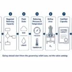
| Required relieving capacity | Governing overpressure scenario | The flow that must be discharged to keep the protected equipment within the approved pressure boundary. |
| Certified / accepted capacity | Selected valve, orifice and test basis | The documented flow performance used to confirm that the selected valve can satisfy the required load. |
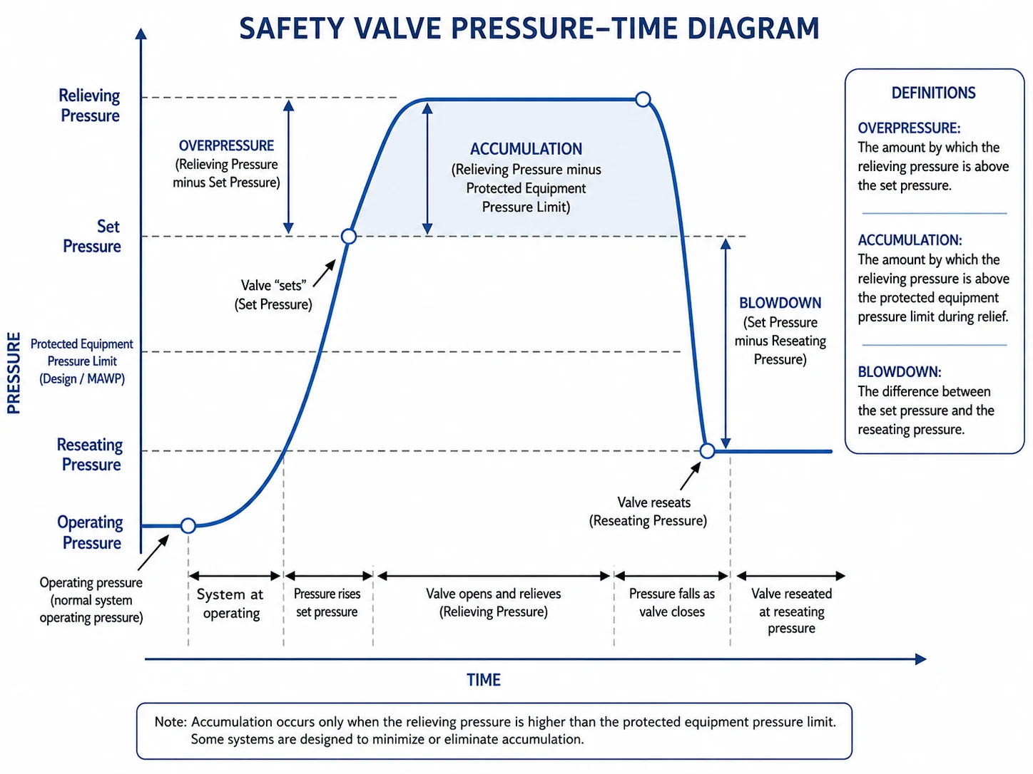
| Overpressure | Set pressure | The pressure increase above set pressure during relief. |
| MAWP / allowable equipment limit | Protected equipment | The approved pressure boundary used by the applicable equipment design basis. |
| Accumulation | MAWP or applicable allowable limit | The pressure increase above the protected equipment limit during relief. |
| Reseating pressure | Valve closing behavior | The inlet pressure at which the valve closes after relieving. |
| Blowdown | Set pressure and reseating pressure | The difference between set pressure and reseating pressure. |
Definition warning: The exact test indication used to establish set pressure can differ by valve type and applicable standard. A generic phrase such as “first visible opening” should not replace the specified test method.
What This Guide Covers
This page explains the pressure relationships around a reclosing safety or pressure-relief valve. It is the site’s main page for set pressure, overpressure, accumulation, blowdown, reseating pressure and cold differential test pressure.
It does not replace:
- the governing relief-scenario calculation;
- the capacity and orifice sizing method;
- the applicable equipment code or jurisdictional requirement;
- the manufacturer’s set-pressure and blowdown procedures;
- the installed back-pressure and piping analysis.
This guide intentionally does not publish one universal set-pressure margin, overpressure allowance, accumulation allowance or blowdown percentage. Those values depend on the protected equipment, governing code, relief scenario, number and arrangement of devices, valve design, fluid, back pressure and project specification.
For the broader decision process, use the Safety Valve Selection Guide. For capacity, use the Safety Valve Sizing and Certified Capacity Guide.
What Is Safety Valve Set Pressure?
Set pressure is the inlet pressure at which the valve is adjusted to demonstrate the specified operating characteristic under defined test conditions. In practical terms, it establishes when the pressure-relief device begins its required opening response.
Set pressure is normally identified on the approved datasheet, valve nameplate and calibration record. It should be selected from the protected equipment’s design basis, MAWP or other applicable allowable pressure, operating conditions, relief arrangement and code requirements.
Set pressure is not a universal percentage above normal operating pressure and should not be selected from an old nameplate alone. For many code-protected systems, the allowable relationship between set pressure and the equipment limit depends on the protected equipment code, single- or multiple-device arrangement, supplemental protection, relief scenario and jurisdiction. Boiler, pressure-vessel and piping requirements should not be mixed.
| Pressure Input | What It Controls | Risk If Misused |
|---|---|---|
| Normal and maximum operating pressure | Operating margin, simmer risk and seat-tightness demand | Repeated leakage or cycling during routine operation |
| MAWP / allowable equipment limit | Protected-equipment pressure boundary and code arrangement | Set pressure approved against the wrong reference |
| Set pressure | Specified opening-response point | Protection begins too late or nuisance lifting occurs |
| Relieving pressure | Capacity calculation and verification condition | Incorrect required area or certified-capacity comparison |
Set Pressure Does Confirm
The required opening-response setting under the specified test basis.
Set Pressure Does Not Confirm
Required capacity, stable full lift, acceptable back pressure, correct blowdown or seat tightness in service.
Why Set Pressure Should Not Be Changed Casually
Increasing set pressure to stop leakage can reduce or invalidate the intended protection of the equipment. Leakage may instead be caused by insufficient operating margin, damaged seating surfaces, contamination, corrosion, thermal distortion, piping loads, back-pressure fluctuations or poor calibration practice.
Do not tighten the adjusting screw as a troubleshooting shortcut. Any set-pressure change should follow the approved engineering, calibration, sealing, tagging and documentation process. Increasing spring compression can leave the protected equipment under-protected even when the visible leakage temporarily decreases.
Composite engineering case
Problem: A gas receiver valve leaked during normal operation, so the set pressure was increased in the field. Cause: The receiver was already operating too close to set pressure and compressor pulsation was producing repeated simmer. The informal adjustment masked the symptom and reduced the intended protection margin. Correction: The plant restored the approved setting, recalibrated and resealed the valve, reviewed pressure-control stability and confirmed the equipment code basis before return to service.
Operating Pressure Margin Below Set Pressure
Operating pressure is the normal pressure of the process. It is not a relief allowance. When normal or maximum operating pressure remains too close to set pressure, a valve may simmer, weep, leak or cycle during routine process fluctuations.
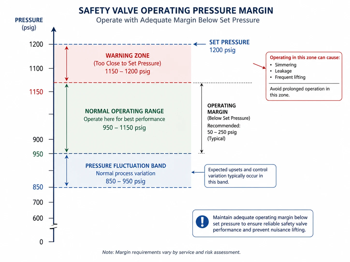
The appropriate margin depends on:
- conventional, balanced or pilot-operated design;
- metal or soft seat;
- process pressure fluctuation and pulsation;
- gas, steam, liquid or two-phase service;
- temperature and thermal cycling;
- superimposed back pressure;
- seat condition and leakage requirement;
- manufacturer guidance and the applicable code.
A pilot-operated valve may support closer operation in suitable clean service, while a conventional spring-loaded valve may require a larger practical margin. This is a design decision, not a reason to apply one percentage to every application. Pilot passages, filters and sensing lines can become unreliable in dirty, waxy, polymerizing, condensable or freezing service.
Seat construction and materials also change the practical margin. Metal seats tolerate high temperature and many severe services but depend on accurate alignment and surface condition. Soft seats may improve tightness in suitable clean service but remain limited by temperature, chemical compatibility, ageing, extrusion and decompression effects.
Composite engineering case
Problem: A spring-loaded PSV repeatedly passed shop calibration but developed leakage within weeks of installation. Cause: Normal gas pressure was close to set pressure and a reciprocating compressor created short pressure peaks. The valve was simmering rather than experiencing one stable relief event. Correction: The operating envelope and control loop were revised, the seat was inspected and restored, and the operating margin was revalidated against the selected valve design.
Cold Differential Test Pressure and Test-Stand Adjustment
Cold differential test pressure (CDTP) is a test-stand adjustment value used when the valve’s cold test condition differs from the intended service condition. Depending on the valve, applicable standard and manufacturer procedure, the adjustment may account for effects such as service temperature or constant superimposed back pressure.
CDTP is important because a valve can be calibrated in a workshop at ambient temperature and without the installed downstream pressure. The workshop setting therefore may need a defined correction so the valve performs at the required set pressure in service.
CDTP is not a generic correction formula. The direction and magnitude of any correction depend on the valve design, spring and material behavior, service temperature, constant superimposed back pressure, bonnet arrangement, manufacturer procedure and applicable standard. Variable superimposed back pressure and built-up back pressure are installed-system conditions and should not be reduced to an unsupported test-stand adjustment.
Required in-service set pressure → identify service corrections → establish approved test pressure → calibrate and document → verify installed basis
The calibration record should state:
- valve tag, model and serial number;
- required in-service set pressure;
- test pressure or CDTP used;
- test medium and test temperature;
- specified back-pressure or temperature correction;
- acceptance tolerance and observed result;
- seal, tag and technician or organization identification.
Do not invent a CDTP correction. Use the applicable standard, approved datasheet and manufacturer procedure. Back pressure does not affect conventional, balanced bellows and pilot-operated valves in the same way, and a test correction does not validate the downstream piping system.
Composite engineering case
Problem: A conventional valve opened below the intended in-service set pressure after installation on a closed header. Cause: The workshop calibration did not include the approved correction for the known constant superimposed back pressure. Correction: Engineering re-established the test basis, recalibrated the valve using the manufacturer procedure, documented the CDTP and separately checked built-up back pressure at relieving flow.
Set Pressure vs Relieving Pressure
Set pressure defines the specified opening-response point. Relieving pressure is the pressure condition used for capacity determination or verification during the relief event.
A valve may begin its opening response at set pressure but require additional pressure rise to reach the lift and flow associated with its rated or certified capacity. This is why a set-pressure certificate does not prove that the selected valve has enough capacity.
Set Pressure Question
At what inlet pressure should the valve display the specified opening characteristic?
Relieving Pressure Question
At what pressure condition is the required or certified relieving flow evaluated?
When approving sizing, compare the required relief load with manufacturer-certified or project-accepted capacity at the correct pressure, temperature, fluid, phase and downstream basis. The effective orifice and certified coefficient—not the inlet connection size—control the documented capacity comparison.
Evidence boundary: A set-pressure certificate shows when the valve was adjusted to respond. A capacity certificate or accepted performance record shows how much flow a defined valve configuration can pass. An API 527 or project seat-tightness report shows leakage performance. These records are not interchangeable.
What Is Safety Valve Overpressure?
Overpressure is the pressure increase above set pressure during a relief event. It is commonly expressed as a percentage of set pressure.
Overpressure (%) = [(Relieving Pressure − Set Pressure) ÷ Set Pressure] × 100
Overpressure is connected to valve performance because the valve generally develops additional lift and flow as pressure rises above set pressure. The amount permitted or used in sizing depends on the applicable code, relief scenario, valve design and project basis.
Overpressure should not be treated as routine operating space. It belongs to the emergency relief condition. The permitted or sizing value should be taken from the actual equipment code, relief arrangement and scenario rather than copied from another service.
Why a Valve Can Open but Still Not Protect the System
If the system pressure continues to rise after the valve opens, possible causes include:
- required capacity greater than the selected valve’s certified capacity;
- wrong relieving-pressure assumption;
- incorrect fluid phase, molecular weight, density, viscosity or temperature;
- insufficient lift or unstable valve motion;
- excessive inlet pressure loss;
- excessive built-up back pressure or an unreviewed common header;
- a relief scenario that was missed or underestimated;
- a same-size replacement with a smaller effective orifice or different certified coefficient.
Composite engineering case
Problem: A valve opened at its required set pressure, but vessel pressure continued to rise. Cause: A debottlenecking project increased the blocked-outlet relief load, while the replacement valve was approved from its flange size and set pressure. Its certified capacity was below the new required load. Correction: The relief case was recalculated, the effective orifice and certified capacity were reselected, and the outlet system was checked at the revised flow.
What Is Accumulation?
Accumulation is the pressure increase above the protected equipment’s MAWP or other applicable allowable pressure limit during a relief event. It describes the pressure experienced by the equipment, not simply the valve’s pressure rise above set pressure.
Accumulation (%) = [(Maximum System Pressure During Relief − MAWP) ÷ MAWP] × 100
Overpressure and accumulation may have the same numerical value only when set pressure equals the reference equipment limit used in the calculation. When set pressure is below MAWP, they are different. Multiple-device arrangements, supplemental devices, fire cases and different protected-equipment codes can also create different approved pressure relationships.
| Term | Reference | Engineering Purpose |
|---|---|---|
| Overpressure | Valve set pressure | Connects the valve’s pressure rise to its relieving behavior and capacity basis. |
| Accumulation | Equipment MAWP or applicable allowable limit | Checks the maximum pressure experienced by the protected equipment. |
Do not copy an accumulation allowance from another project. The permitted value depends on the equipment code, relief scenario, number and arrangement of relief devices, jurisdiction and project specification.
What Is Blowdown and Reseating Pressure?
Reseating pressure is the inlet pressure at which the valve closes after relieving. Blowdown is the difference between set pressure and reseating pressure, commonly expressed as a percentage of set pressure.
Blowdown (%) = [(Set Pressure − Reseating Pressure) ÷ Set Pressure] × 100
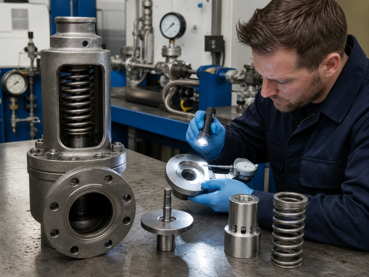
If blowdown is too large for the process, pressure may fall farther than necessary before closure, extending discharge and process interruption. If it is too narrow for the process and installed conditions, the valve may cycle, chatter or fail to reseat cleanly.
Blowdown should not be altered by moving adjusting rings, pilot settings or internal components without the manufacturer’s approved procedure and the applicable test basis. A valve can meet set pressure and still have unacceptable closing behavior.
Reseating behavior can also be affected by:
- back pressure and outlet pressure fluctuation;
- inlet pressure loss;
- valve oversizing and low lift;
- disc, nozzle and guide condition;
- spring, adjusting rings, pilot settings and assembly condition;
- fluid phase and two-phase discharge;
- process pressure control and pulsation;
- temperature, deposits, corrosion and pipe strain.
Composite engineering case
Problem: A steam valve opened correctly but stayed open longer than expected and leaked after reseating. Cause: Blowdown-ring positions had been changed during a previous overhaul, and the discharge line retained condensate. Correction: The approved ring settings were restored, drainage and outlet support were corrected, and the valve completed set-pressure, blowdown and seat-tightness verification before resealing.
Pressure-Term Formula Summary
| Calculation | Formula | Reference Pressure |
|---|---|---|
| Overpressure | (Prelieving − Pset) ÷ Pset × 100 | Set pressure |
| Accumulation | (Pmaximum − MAWP) ÷ MAWP × 100 | Protected equipment limit |
| Blowdown | (Pset − Preseat) ÷ Pset × 100 | Set pressure |
| Operating margin | (Pset − Poperating) ÷ Pset × 100 | Set pressure; use only as a descriptive margin unless the governing procedure defines it |
Use consistent units and the pressure basis required by the applicable calculation procedure. Do not mix gauge and absolute pressure values within one formula, compare a set pressure from one scenario with a maximum pressure from another, or treat the descriptive operating-margin formula as a code acceptance rule.
Formula limitation: These equations explain terminology. They do not establish the allowable percentage, the required relieving pressure, the valve coefficient or the capacity method for a specific project.
Illustrative Example: Why Overpressure and Accumulation Differ
Illustrative calculation — not a code allowance
| Equipment MAWP | 10.0 barg |
|---|---|
| Valve set pressure | 9.5 barg |
| Maximum pressure during relief | 10.5 barg |
| Reseating pressure | 8.8 barg |
Overpressure
(10.5 − 9.5) ÷ 9.5 × 100 = 10.5% approximately.
Accumulation
(10.5 − 10.0) ÷ 10.0 × 100 = 5.0%.
Blowdown
(9.5 − 8.8) ÷ 9.5 × 100 = 7.4% approximately.
Lesson: The same maximum relief pressure produces different overpressure and accumulation values because the reference pressures are different.
Boundary: This example uses a consistent gauge-pressure basis only to demonstrate the reference-point difference. It does not state an allowable code limit or a complete sizing calculation.
How Back Pressure Interacts with Set Pressure and Blowdown
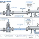
Back pressure is outlet-side pressure acting on the valve. It may exist before opening or be generated by discharge flow. Depending on the design, it can affect opening response, lift, capacity, blowdown and reseating.
A conventional spring-loaded valve, balanced bellows valve and pilot-operated valve should not be assumed to respond identically. Constant superimposed back pressure may be considered in an approved test adjustment for some designs, while variable or built-up back pressure requires an installed-system review.
| Valve Design | Pressure-Term Concern | Review Boundary |
|---|---|---|
| Conventional spring-loaded | Outlet pressure can influence the net force acting on the disc and can change set response, blowdown or capacity. | Confirm allowable constant, variable and built-up back pressure from product data and the installed calculation. |
| Balanced bellows | Bellows reduce specified back-pressure force effects but add pressure, fatigue, corrosion and venting limits. | Do not plug the bonnet vent; check bellows failure consequences and capacity corrections. |
| Pilot-operated | Pilot design can control main-valve pressure response differently and may support close operating pressure in clean service. | Check sensing lines, pilot passages, drainage, filters, freezing, fouling and downstream-pressure behavior. |
Use the Safety Valve Back Pressure Guide for superimposed, built-up and total back-pressure analysis, and the Back Pressure and Bellows Engineering Guide for valve-configuration and bonnet-vent review.
A correct bench set pressure does not validate the outlet system. A valve can pass calibration and still chatter or reseat poorly because of the installed discharge piping.
Calibration, Sealing and Field Adjustment
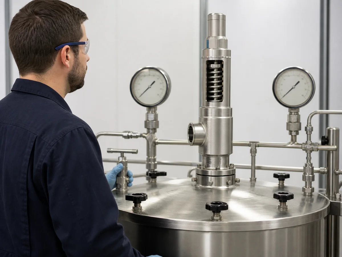
Set-pressure verification should be performed using an approved procedure, suitable test equipment, the correct test medium and traceable instrumentation. The final record should identify the physical valve, the as-found condition where applicable, the accepted as-left adjustment and every service correction used.
After disassembly, lapping, spring replacement, trim replacement or any adjustment that can affect function, the repair scope should restore more than the visible set point. Internal alignment, seat condition, spring range, blowdown components, bellows or pilot parts, seat tightness, locking and sealing should be controlled under the applicable quality system.
Calibration Record Checklist
Valve tag, model and serial number
Nameplate set pressure
Required in-service set pressure
CDTP or test pressure where applicable
Test medium and temperature
Specified back-pressure correction
Observed opening characteristic
Reseating or blowdown result where tested
Seat-tightness result when specified
Instrument identification and calibration status
Final seal and tag condition
Technician, organization and approval date
As-found and as-left results where applicable
Parts replaced and approved interchangeability
For seat leakage testing, use the API 527 Seat Tightness Test Guide. For repaired valves, the applicable owner, jurisdiction and repair authorization route should be followed. Where required, verify the repair organization’s National Board VR authorization rather than assuming any valve shop can alter critical parts or settings.
Why Field Adjustment Is High Risk
Turning an adjusting screw changes only one part of the system. It does not correct an undersized valve, unstable outlet system, damaged seat, wrong fluid assumption or excessive operating pressure. Uncontrolled adjustment also breaks traceability between the valve, nameplate and calibration record.
Return-to-service hold point: Do not return an adjusted or repaired valve to service until the approved set-pressure result, seat-tightness result where specified, seal status, tag, repair record and installed service basis agree.
Pressure-Related Safety Valve Troubleshooting Matrix
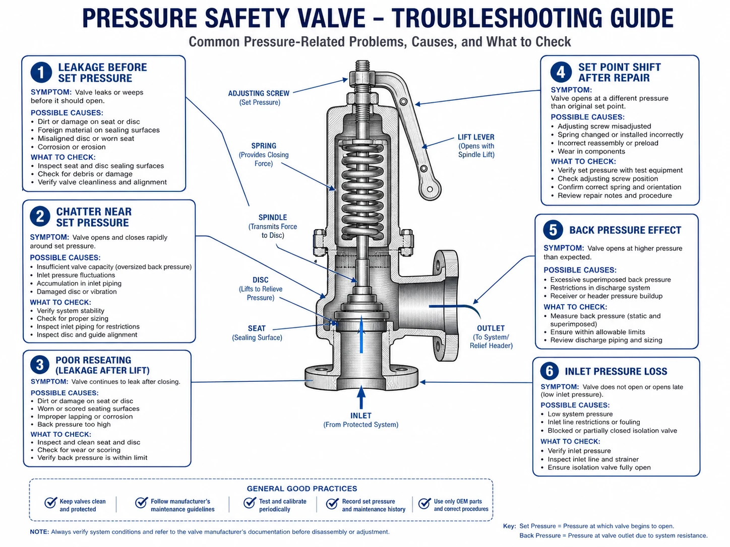
| Observed Symptom | Possible Pressure-Related Causes | Recommended Review |
|---|---|---|
| Leaks or simmers before set pressure | Operating pressure too close to set pressure, pressure pulsation, superimposed back pressure | Operating margin, pressure trend, seat condition, piping load and calibration |
| Opens earlier or later than expected | Wrong test basis, CDTP error, temperature effect, constant back pressure, set drift | Datasheet, test procedure, service correction and calibration record |
| Chatters near set pressure | Inlet loss, oversized valve, process instability, built-up back pressure, unsuitable blowdown | Inlet/outlet calculation, sizing, process trend and valve design |
| Opens but system pressure continues rising | Insufficient certified capacity, wrong relieving pressure, missed relief case, reduced lift | Required load, orifice, certified capacity, fluid phase and back pressure |
| Does not reseat cleanly | Narrow or unsuitable blowdown, changing back pressure, damaged guide or seat, process pressure remains high | Reseating trend, outlet pressure, internals and operating control |
| Set point shifts after repair | Incorrect assembly, spring or seat changes, wrong test correction, poor calibration control | Repair record, parts, CDTP, test equipment, seal and tag |
| Correct set pressure but insufficient protection | Required load increased, effective orifice too small, wrong certified coefficient or missed relief case | Relief calculation, selected orifice, certified capacity and process modification history |
| Bench setting correct but field opening differs | Unapplied temperature or constant back-pressure correction, variable back pressure, inlet loss or pressure-measurement location | CDTP basis, field instruments, upstream pressure loss and outlet-system pressure |
For leakage after discharge, see Why Safety Valves Leak After Popping. For inlet and outlet piping, use the Safety Valve Installation Guide. For repeated problems, compare process trends, as-found test results and installed piping before approving another adjustment.
When Engineering Approval Must Be Held
Unknown MAWP or Code Basis
The set pressure and accumulation limit cannot be approved without the protected equipment basis.
Unknown Required Capacity
A correct opening setting does not prove adequate pressure protection.
Unclear Pressure References
Gauge, absolute and different scenario values are being mixed.
Unresolved Back Pressure
The installed set response, capacity and reseating behavior may differ from the test stand.
Unapproved Set-Pressure Change
The valve nameplate and equipment protection basis would no longer agree.
Missing CDTP Basis
Temperature or constant back-pressure corrections have not been documented.
Repeated Chatter or Leakage
The root cause may be system-level rather than a calibration-only problem.
Calibration and Nameplate Conflict
The physical valve cannot be traced to the approved setting and record.
Unknown Fluid Phase or Relieving Temperature
The relieving pressure, required area, materials and certified-capacity basis cannot be confirmed.
Unverified Valve Type or Orifice
Connection size and set pressure do not prove the opening characteristic or relieving capacity.
Eight-Step Pressure-Term Review Workflow
- Confirm the protected equipment limit.
Identify MAWP, design basis, equipment code and jurisdiction. - Confirm operating pressure and fluctuations.
Review normal, maximum and transient process pressure. - Approve the set pressure.
Connect the valve setting to the protected equipment and relief arrangement. - Establish the relieving pressure and capacity basis.
Use the approved relief scenario, fluid properties, required load, selected orifice and applicable overpressure basis. - Check accumulation separately.
Compare maximum system pressure with the equipment limit. - Review blowdown and reseating needs.
Confirm that the process can fall far enough for stable closure. - Evaluate service corrections and installation.
Review CDTP, temperature, valve type, materials, back pressure, inlet loss and outlet piping. - Document calibration and approval.
Align datasheet, relief calculation, capacity evidence, nameplate, as-found/as-left test record, seal, tag and maintenance system.
Pressure Data to Include in an RFQ or Repair Order
| Data Item | Why It Is Required |
|---|---|
| Protected equipment and tag | Defines the pressure boundary and records link. |
| MAWP / design pressure | Provides the equipment reference for set pressure and accumulation. |
| Normal and maximum operating pressure | Shows the practical margin below set pressure. |
| Required set pressure | Defines the valve’s approved opening-response setting. |
| Relief scenario and required capacity | Connects the setting to the pressure-protection duty. |
| Selected valve type, effective orifice and certified capacity | Confirms that the proposed device can deliver enough verified flow and has the correct opening behavior. |
| Relieving pressure and temperature | Provides the capacity and material basis. |
| Superimposed and built-up back pressure | Supports valve-type, CDTP and installed-performance review. |
| Required blowdown or reseating behavior | Supports stable process recovery where specified. |
| Test medium, test temperature and CDTP basis | Prevents inconsistent workshop calibration and undocumented service corrections. |
| Seat type and critical trim materials | Supports leakage, corrosion, galling, temperature and service-life review. |
| Seat-tightness requirement | Defines the leakage test and acceptance record. |
| Certificate, seal and tagging requirements | Preserves traceability from calibration to installation. |
| As-found / as-left and repair records | Shows set drift, previous damage, parts replaced and final return-to-service condition. |
Use the Safety Valve Procurement Checklist for the full RFQ and supplier-document package.
Standards and Authoritative References
The exact allowable values and test methods depend on the equipment, application, code edition and jurisdiction. The following references should be connected to a specific engineering decision.
| Reference | Role in This Topic | Link |
|---|---|---|
| ASME BPVC Section XIII | Overpressure-protection rules for pressurized equipment and pressure-relief devices, including design, testing and marking topics. | ASME official page |
| ASME BPVC Section I / Section VIII, Division 1 | Protected-equipment context for power boilers and pressure vessels; used with the applicable overpressure-protection route. | Section I / Section VIII-1 |
| API 520 Part I | Sizing and selection, including the pressure and capacity basis used when choosing pressure-relieving devices in covered applications. | API official page |
| API 520 Part II | Installation review, including inlet and outlet conditions and an engineering-analysis route for suitable installations. | API official page |
| API 521 | Pressure-relieving and depressuring-system analysis, including relief scenarios and disposal-system conditions. | API official page |
| API 527 | Seat-tightness test methods and acceptance criteria; it is not a sizing, accumulation or set-pressure-selection standard. | ZOBAI API 527 Guide |
| ISO 4126-1 | General product requirements for safety valves; product compliance does not replace application-specific sizing and installation analysis. | ISO official page |
| NBIC Part 4 / National Board VR | Installation, in-service inspection and repair framework where NBIC applies, plus authorization for pressure-relief-valve repair. | NBIC / VR authorization |
| ZOBAI ASME Guide | Procurement-oriented overview of ASME pressure-relief requirements and documentation. | ASME Safety Valve Standards |
Standards notice: A web article does not replace the official copyrighted standard, the required edition, the protected equipment design documents, manufacturer instructions or the responsible engineer’s approval.
FAQ About Set Pressure, Overpressure and Blowdown
What is safety valve set pressure?
It is the inlet pressure at which the valve is adjusted to demonstrate the specified opening characteristic under defined test conditions. It establishes the required response point but does not prove capacity or stable reseating.
What is the difference between set pressure and relieving pressure?
Set pressure defines the specified opening-response point. Relieving pressure is the pressure condition used to determine or verify relieving capacity.
What is safety valve overpressure?
Overpressure is the pressure increase above set pressure during relief, commonly expressed as a percentage of set pressure.
What is the difference between overpressure and accumulation?
Overpressure is referenced to valve set pressure. Accumulation is referenced to the protected equipment’s MAWP or applicable allowable pressure limit.
What is safety valve blowdown?
Blowdown is the difference between set pressure and reseating pressure, commonly expressed as a percentage of set pressure.
What is cold differential test pressure?
CDTP is an approved test-stand adjustment pressure used when service conditions such as temperature or specified constant back pressure require correction from the cold test condition.
Can set pressure be increased to stop leakage?
It should not be increased as an informal fix. The leakage cause should be diagnosed, and any approved setting change must be recalibrated, sealed, tagged and documented.
Why does a valve chatter near set pressure?
Possible causes include excessive inlet loss, valve oversizing, process instability, built-up back pressure, outlet-system resistance or unsuitable blowdown behavior.
Why can a valve pass calibration but fail in service?
The test stand may not reproduce service temperature, back pressure, inlet loss, outlet resistance, process pulsation or fluid conditions.
Is there one required operating margin below set pressure?
No. The required margin depends on valve design, seat, medium, pressure fluctuation, temperature, back pressure, applicable code and manufacturer guidance.
Can set pressure be higher than MAWP?
There is no universal answer that applies to every protected system. The relationship depends on the equipment code, relief-device arrangement, supplemental protection, relief scenario and jurisdiction. Set pressure should be approved from the actual protected-equipment basis rather than a generic percentage.
Does the same connection size mean the same relieving capacity?
No. Connection size confirms the physical interface. Effective orifice, lift, coefficient, certified fluid and valve configuration determine documented relieving capacity.
When must a repaired safety valve be recalibrated and resealed?
After work that can affect the valve’s function or pressure setting, the applicable repair procedure should define inspection, set-pressure verification, seat-tightness testing where specified, documentation, locking and resealing before return to service.
Need a Set-Pressure or Calibration Review?
Send the protected equipment, MAWP, operating-pressure trend, required set pressure, relief scenario, required capacity, relieving conditions, back pressure, valve nameplate and as-found/as-left calibration record for a technical review.
Upload Valve Data Request a Safety Valve Quote