A pressure relief valve (PRV) is a self-actuated, reclosing pressure-protection device that opens when inlet pressure reaches its specified opening condition, discharges fluid, and closes again after pressure falls through the valve’s reseating range. Its purpose is to keep boilers, pressure vessels, pipelines, heat exchangers, compressor packages and other pressurized systems within the allowable pressure …

A pressure relief valve (PRV) is a self-actuated, reclosing pressure-protection device that opens when inlet pressure reaches its specified opening condition, discharges fluid, and closes again after pressure falls through the valve’s reseating range. Its purpose is to keep boilers, pressure vessels, pipelines, heat exchangers, compressor packages and other pressurized systems within the allowable pressure boundary established by the applicable equipment code and approved relief basis.
“Pressure relief valve” is a broad industry term. Depending on the project standard, fluid and opening characteristic, the actual device may be identified as a safety valve, relief valve, safety relief valve, pressure safety valve or PSV. The abbreviation does not establish the valve type, certified capacity, service fluid, back-pressure capability, seat construction or code acceptance.
A PRV is not selected from connection size alone. Engineering must first define the protected equipment and credible overpressure scenario, calculate the required relieving capacity, then verify that the proposed valve’s certified or otherwise accepted capacity, effective orifice, set pressure, materials and installed performance satisfy that duty.
Engineering takeaway: A PRV that opens at the correct set pressure may still be unsuitable if it cannot pass the governing relief load, becomes unstable because of inlet pressure loss or outlet back pressure, uses incompatible nozzle, disc, guide, spring or seal materials, or lacks the required code and test evidence.
60-Second Pressure Relief Valve Answer
| Question | Practical Engineering Answer |
|---|---|
| What does a PRV do? | It opens automatically during a defined overpressure condition, discharges fluid and recloses after pressure falls. |
| What makes it open? | Inlet pressure reaches the specified opening characteristic for that valve type, test medium and standard. |
| What can it protect? | Boilers, pressure vessels, exchangers, compressor systems, piping, pump discharge and blocked-in liquid sections. |
| What fluids can it handle? | Steam, gas, vapor, liquid, flashing or qualified two-phase service, depending on design, sizing method and certification. |
| Does set pressure prove capacity? | No. Set pressure identifies the opening condition; required flow must be checked against certified or accepted capacity. |
| Does connection size prove capacity? | No. Valves with the same inlet size can have different effective orifices, lift and certified capacities. |
| How do overpressure and accumulation differ? | Overpressure is referenced to set pressure; accumulation is referenced to the protected equipment’s MAWP or allowable pressure boundary. |
| What affects reseating? | Blowdown, operating margin, back pressure, seat condition, guide alignment, contamination and valve design. |
| Is PRV always “pressure relief valve”? | No. PRV can also mean pressure reducing valve. The full device function should be written on an RFQ, P&ID note or replacement order. |
| Is a PRV a normal control valve? | No. It is an abnormal-condition protection device, not the primary process pressure controller. |
Approval hold point: Final selection is not defensible while the governing relief scenario, required relieving capacity, relieving fluid phase or outlet back-pressure condition remains unknown. A supplier may suggest a preliminary family, but the pressure-protection duty has not been verified.
What Is a Pressure Relief Valve?
A pressure relief valve is a reclosing pressure-relief device that responds automatically to inlet pressure. When the specified opening condition is reached, it creates a discharge path from the protected system. After the pressure source is reduced or isolated and pressure falls, the valve is intended to reseat.
The PRV is one layer in an overpressure-protection system. Other layers may include process control, alarms, shutdown systems, rupture disks, depressuring systems, isolation philosophy and operating procedures. The correct architecture depends on the protected equipment, hazard, relief scenarios, code route and owner requirements.
Valve Function
Open, relieve the required load, remain stable and reseat under the approved operating and installation conditions.
System Function
Keep the protected equipment within the code-permitted pressure boundary during the governing overpressure event.
For ASME applications, the equipment construction section and the overpressure-protection rules work together. The equipment MAWP, allowable accumulation, set-pressure arrangement and relieving capacity must therefore be treated as one protection basis rather than as independent catalogue values.
Terminology note: This page uses “pressure relief valve” as a broad introductory term. A project may use safety valve, relief valve, safety relief valve, PSV or PRV more specifically. The approved datasheet, service fluid, opening characteristic and certification basis control the final definition.
What Equipment Does a Pressure Relief Valve Protect?
Pressure Vessels
Receivers, separators, reactors, filters, storage vessels and process drums.
Boilers and Steam Systems
Steam boilers, headers, generators, clean-steam equipment and heated vessels.
Compressors and Gas Systems
Compressor packages, air receivers, gas skids and downstream low-pressure equipment.
Heat Exchangers
Low-pressure sides exposed to tube rupture, blocked outlet or thermal expansion.
Liquid Piping
Blocked-in liquid sections, pump discharge lines and hydraulic systems.
Process and OEM Skids
Packaged equipment whose relief device must still match the final installed system.
The protected equipment establishes the pressure boundary, MAWP or applicable allowable limit, relief scenarios and code route. The valve cannot be evaluated independently of that equipment.
Why a Pressure Relief Valve Is Not a Normal Valve
An isolation or control valve is normally selected to stop, route or regulate process flow. A pressure relief valve is selected to protect equipment during an abnormal condition. That changes the technical approval process.
| Normal Process Valve Review | Pressure Relief Valve Review |
|---|---|
| Line size and pressure class | Protected equipment, MAWP and set pressure |
| Normal flow and pressure drop | Governing relief case and required relieving capacity |
| Control or isolation function | Automatic opening, relieving and reseating behavior |
| Body and trim materials | Body, nozzle, disc, guide, spring, bellows, pilot and seat materials |
| Actuator and control signal | Valve design, operating margin, back pressure and certified performance |
| General inspection documents | Calibration, capacity evidence, pressure test, seat tightness and traceability records |
Mechanical fit is not engineering equivalence. A replacement valve may have the same connections and pressure class yet use a smaller orifice, different capacity basis, unsuitable materials or different back-pressure limits.
How Does a Pressure Relief Valve Work?
-
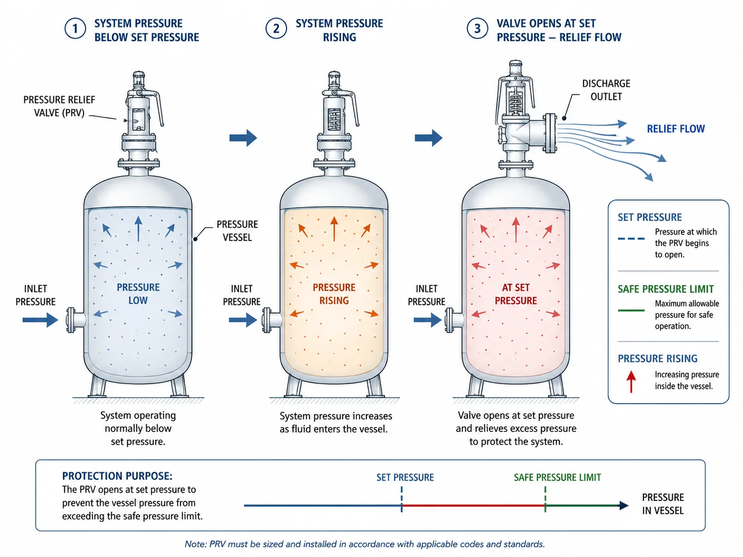
The valve remains closed during normal operation.
A spring, pilot-controlled dome pressure or another approved closing mechanism keeps the disc or main valve on its seat. Adequate operating margin and suitable seat construction are needed to limit simmer and leakage. -
A credible overpressure source raises system pressure.
Examples include blocked outlet, external fire, thermal expansion, regulator failure, tube rupture, gas blow-by or process upset. -
The specified opening condition is reached.
The valve exhibits the opening characteristic defined by its design and test basis. A pop-action gas or steam valve, proportional liquid relief valve and pilot-operated valve should not be assumed to respond identically. -
Lift and flow area develop.
Disc geometry, spring force, pilot action, fluid forces, pressure rise, inlet loss and outlet back pressure affect the available lift and stability. -
The valve relieves the required flow.
The selected effective orifice and certified or otherwise accepted capacity must meet or exceed the governing required relieving load at the approved relieving conditions. -
Pressure remains within the permitted event boundary.
Overpressure is referenced to set pressure, while accumulation is referenced to the protected equipment’s MAWP or other allowable pressure limit. The applicable code and scenario define the permitted boundary. -
The overpressure source is controlled and pressure falls.
Inventory is discharged, incoming energy or flow is reduced, or the initiating fault is removed. -
The valve reseats.
The closing mechanism returns the disc to the seat. Blowdown, back pressure, process pressure recovery, seat damage, guide alignment and contamination influence whether the valve closes tightly and remains stable.
Spring-Loaded Operation
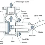
A compressed spring applies closing force through the spindle and disc assembly. Conventional and balanced-bellows versions differ in how outlet pressure influences the force balance.
Pilot-Operated Operation
A pilot and system pressure control the main valve. Performance depends on the pilot design, sensing line, exhaust arrangement, seals and medium cleanliness.
For the detailed direct-spring force sequence, use How a Spring-Loaded Safety Valve Works.
Set-pressure boundary: Set pressure is not one universal “first visible movement” point. The specified opening characteristic depends on valve design, test medium and the applicable standard. A passed set-pressure test does not prove certified capacity, seat tightness or installed-system stability.
What Happens After a PRV Lifts?
After a real relief event, the valve may require inspection when the lift involved chatter, severe vibration, dirty or corrosive fluid, fire exposure, abnormal back pressure, prolonged discharge or post-lift leakage. Re-lapping the seat alone is not a complete corrective action when the root cause is inlet pressure loss, oversizing, discharge-header resistance or unsuitable materials.
Pressure Relief Valve vs Safety Valve vs PSV
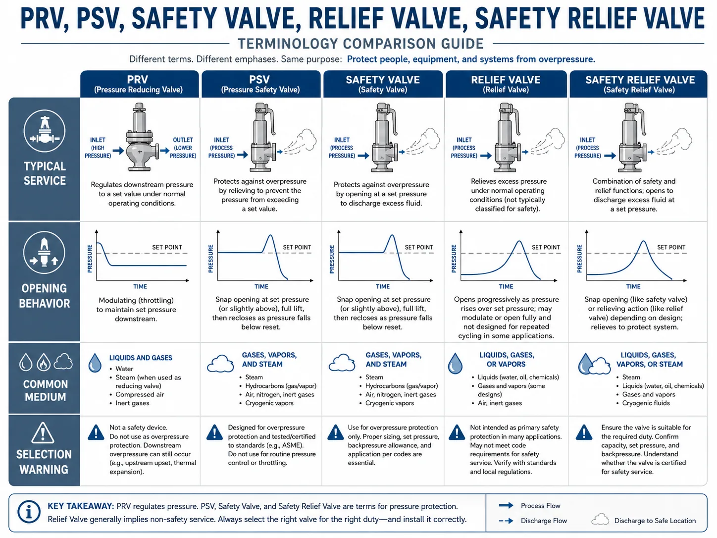
| Term | Common Use | Main Caution |
|---|---|---|
| Pressure relief valve | Broad term for an automatic pressure-relieving valve | Does not define fluid, opening characteristic or construction. |
| Relief valve | Often associated with liquid or proportional-opening duty | Industry usage varies; do not assume liquid-only. |
| Safety valve | Often associated with rapid-opening steam, gas or vapor duty | The name does not prove capacity or code acceptance. |
| Safety relief valve | Broad combined term for specified gas or liquid service | Actual service and capacity basis must be stated. |
| PSV | Common process-plant tag for a pressure safety or relief device | Does not identify spring, bellows or pilot construction. |
| PRV | Often pressure relief valve; sometimes pressure reducing valve | Always write the full function in an RFQ. |
Use PRV vs PSV vs Safety Valve vs Relief Valve for the full terminology comparison.
Main Types of Pressure Relief Valves
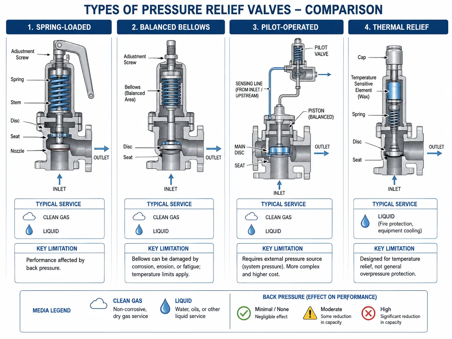
| Valve Type | Basic Principle | Typical Strength | Main Selection Boundary |
|---|---|---|---|
| Conventional spring-loaded | Spring force directly opposes the inlet-pressure force acting on the disc. | Simple, inspectable and widely used for many steam, gas, air and liquid duties. | Operating margin, inlet pressure loss, outlet back pressure, blowdown and required capacity. |
| Balanced bellows | A bellows is added to reduce the influence of outlet pressure on the moving assembly. | Useful where superimposed or built-up back pressure would adversely affect a conventional valve. | Bellows pressure and fatigue limits, corrosion, bonnet venting, failure mode and capacity corrections. |
| Pilot-operated | A pilot and system pressure control the main valve or dome pressure. | Tight shutoff and selected clean, high-pressure, large-capacity or high operating-ratio duties. | Pilot cleanliness, sensing and exhaust routing, seals, condensation, freezing, fouling and maintenance access. |
| Thermal relief valve | A relatively small valve relieves thermal expansion of trapped liquid. | Protects blocked-in liquid sections where heat input causes pressure rise. | Trapped volume, liquid properties, set pressure, safe discharge and whether flashing can occur. |
| Controlled safety pressure relief system | An external control function operates the main relieving valve under the applicable product system. | May be used where a controlled arrangement is specifically engineered and accepted. | System architecture, power or control reliability, applicable ISO 4126-5 route and project acceptance. |
Spring-Loaded vs Pilot-Operated Selection Boundary
A pilot-operated valve is not automatically superior because the set pressure is high or the outlet is connected to a header. It may provide tight shutoff and favorable performance in a suitable clean service, but small pilot passages can be affected by particles, wax, polymer, condensate, ice or corrosion products. A direct spring-loaded valve may be more tolerant of dirty service, while a balanced-bellows design may be preferred when back pressure affects a conventional valve and the bellows material and venting are acceptable.
Composite field example: A pilot-operated PRV was selected for a clean-gas duty because tight shutoff near set pressure was important. After condensate and rust entered the sensing line, the pilot response became inconsistent. The corrective action was not simply to replace the pilot seat; the team corrected drainage and contamination control and reassessed whether the service was clean enough for the pilot design.
For design comparison, use Spring-Loaded vs Pilot-Operated Safety Valves and the Back Pressure and Bellows Engineering Guide.
Key Pressure Relief Valve Parameters
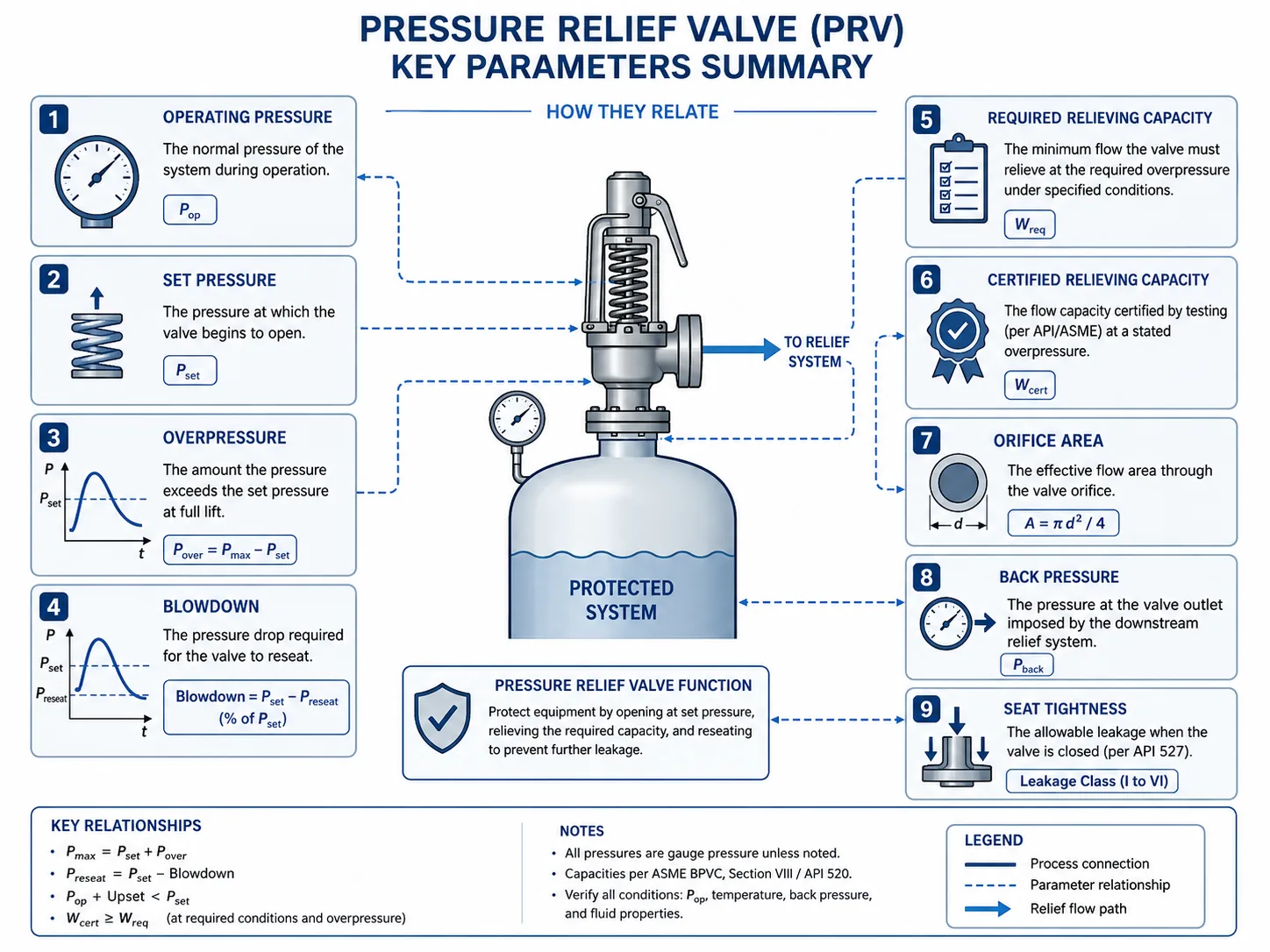
| Parameter | What It Affects | What It Does Not Prove |
|---|---|---|
| Operating pressure | Normal seat loading, leakage tendency and operating margin below the opening region. | That the margin is adequate for the selected valve and process stability. |
| Set pressure | When the valve exhibits its specified opening characteristic under defined conditions. | Full lift, sufficient capacity, acceptable accumulation or tight reseating. |
| Overpressure | The pressure increase above set pressure available while the valve is relieving. | The accumulation relative to the protected equipment’s MAWP. |
| Accumulation | The temporary pressure increase above MAWP or another allowable equipment pressure boundary. | That the selected valve has enough capacity to remain within that boundary. |
| Relieving pressure | The pressure condition used in the approved capacity evaluation. | That the downstream pressure and installation basis are acceptable. |
| Required relieving capacity | The minimum flow generated by the approved governing overpressure scenario. | That any proposed valve can pass that load. |
| Certified / documented capacity | The identified valve model and orifice performance under stated fluid and pressure conditions. | Suitability under different fluid, temperature, back-pressure or trim conditions. |
| Effective orifice / flow area | The rated flow area and therefore the potential relieving capacity. | Mechanical connection size or stable performance if grossly oversized. |
| Inlet pressure loss | Pressure available at the nozzle after flow begins and the risk of cycling or chatter. | Outlet-system suitability. |
| Back pressure | Opening force balance, lift, effective capacity, blowdown and reseating, depending on design. | That a bench-calibrated valve will behave identically after installation. |
| Blowdown / reseating | The pressure range between opening and closure and the process recovery behavior. | Closed-seat leakage acceptance. |
| Seat tightness | Leakage while closed at a specified test condition. | Required capacity, certified capacity or installed stability. |
| Materials | Corrosion, erosion, galling, sticking, leakage, temperature limits and service life. | Compatibility unless the actual fluid composition, temperature and failure mechanism are known. |
Detailed pressure definitions belong on Set Pressure, Overpressure, Accumulation and Blowdown. Capacity calculations belong on the Safety Valve Sizing and Certified Capacity Guide. Seat leakage is a separate acceptance topic covered in the API 527 Seat Tightness Guide.
Composite field example: A replacement valve opened at the approved set pressure but could not control vessel pressure during the revised blocked-outlet case. The cause was not calibration; the new valve had insufficient certified capacity for the increased process flow. The solution was to revalidate the relief calculation and effective orifice rather than adjust the set pressure.
Evidence boundary: A set-pressure certificate, seat-tightness report, certified-capacity record and installation review answer four different engineering questions. None should be used as a substitute for the others.
Where Are Pressure Relief Valves Used?
| Application | Typical Overpressure Concern | Additional Review |
|---|---|---|
| Pressure vessel | Blocked outlet, fire, regulator failure or process upset | MAWP, relief scenario, capacity and equipment code |
| Steam boiler / header | Excess steam generation or blocked discharge | Steam capacity, temperature, drainage and reaction force |
| Air receiver | Compressor control failure or blocked outlet | Pressure cycling, operating margin and pulsation |
| Heat exchanger | Tube rupture, blocked side or thermal expansion | High-to-low pressure interaction and fluid phase |
| Oil, gas, LNG or refinery system | Process upset, fire, gas blow-by or blocked flow | Flare/header back pressure, materials and simultaneous relief |
| Blocked liquid line | Thermal expansion | Discharge destination, material and small-flow basis |
| Process skid | Package-specific failure or upstream pressure source | Final site connections, owner specification and documentation |
What Causes a Pressure Relief Valve to Open?
The valve opens because pressure reaches its specified response condition. The reason pressure rises is called the relief scenario. That scenario determines the required flow and is therefore more important than the catalogue model at the beginning of selection.
Blocked Outlet
Incoming flow continues while the normal discharge path is closed or restricted.
External Fire
Heat input expands vapor or vaporizes liquid inside exposed equipment.
Thermal Expansion
Trapped liquid expands between closed isolation points.
Regulator or Control Failure
High upstream pressure or excess flow enters lower-pressure equipment.
Heat-Exchanger Tube Rupture
High-pressure fluid enters the lower-pressure side.
Reaction or Process Upset
Gas generation, heating, cooling failure or abnormal chemistry increases pressure.
Scenario boundary: This overview does not calculate relief loads. Fire, tube rupture, two-phase flow and reactive cases require the applicable engineering method and project assumptions.
Pressure Relief Valve Selection Basics
This page explains what a PRV is. Final selection should move from definition to the protected equipment and governing relief duty.
Protected equipment → credible relief scenario → required relieving capacity → pressure basis → medium and phase → valve type → certified capacity → back pressure → materials → installation → tests and documents
Protected equipment, MAWP and design temperature identified
Governing relief case approved
Required relieving capacity available with units and revision
Operating, set and relieving pressure confirmed
Overpressure or accumulation basis confirmed
Medium composition and relieving phase confirmed
Relieving temperature confirmed
Superimposed and built-up back pressure reviewed
Valve design selected for the actual service
Effective orifice and certified capacity verified
Body, nozzle, disc, guide, spring, bellows, pilot and seat materials verified
Inlet and outlet piping reviewed
Code, testing, marking and certificate scope defined
Inspection, repair and recalibration route defined
Material Compatibility Is a Component-Level Decision
Specifying only the body material is not enough. The nozzle and disc control seat integrity; the guide and spindle control movement; the spring controls calibrated closing force; the bellows and pilot components add their own corrosion and fatigue limits; and soft seats or O-rings can be restricted by temperature, chemistry, ageing and decompression. Sour service may require NACE MR0175 / ISO 15156 review when H2S service and the project specification make it applicable.
Inspection, Recalibration and Repair Boundary
There is no universal inspection interval for every PRV. The interval depends on jurisdiction, equipment code, service severity, fluid cleanliness, corrosion, lift history, previous as-found results and owner procedures. After disassembly, spring or trim replacement, adjustment or repair, the valve should be tested, documented, locked or sealed and returned to service through the applicable quality system. Where required, a National Board VR-authorized repair route may apply.
Repair-control example: A valve returned from maintenance looked clean and passed a visual inspection, but the as-left set pressure had shifted because the spring and adjusting screw were disturbed during disassembly. The valve was removed again, calibrated, seat-tested, tagged and resealed. The lesson is that cleaning or lapping is not the same as verified return to service.
Use the Safety Valve Selection Guide for the full process, the Safety Valve Material Selection Guide for component-level compatibility, and the Pressure Relief Valves product gateway when the engineering basis is ready for model review.
Common Pressure Relief Valve Mistakes
Selecting by Connection Size
The valve fits the nozzle but may have the wrong effective orifice or insufficient certified capacity.
Confusing Set Pressure With Capacity
A correct opening setting does not prove the valve can relieve the governing load.
Ignoring Fluid Phase
Gas, steam, liquid, flashing and two-phase sizing methods are not interchangeable.
Ignoring Back Pressure
Outlet pressure can change lift, stability, effective capacity, blowdown and reseating.
Ignoring Inlet Pressure Loss
A restrictive inlet can cause pressure collapse at the nozzle, cycling and chatter after the valve opens.
Using PRV Without the Full Function
The buyer may confuse a pressure relief valve with a pressure reducing valve.
Copying an Old Model Number
Throughput, relief scenarios, header pressure, materials or owner requirements may have changed.
Reviewing Body Material Only
Nozzle, disc, guide, spring, bellows, pilot, gaskets and seat materials can govern reliability.
Assuming Pilot-Operated Is Always Better
Dirty, wet, freezing, crystallizing or polymerizing media can restrict pilot and sensing passages.
Accepting a Generic Certificate Pack
Documents may not cover the supplied model, size, material, set pressure, serial number or manufacturing entity.
Repairing Seat Damage Without Finding the Cause
Chatter, oversizing, back pressure or contamination can damage a newly repaired seat again.
Returning a Repaired Valve Without Recalibration
Cleaning or lapping does not prove the final set pressure, seat tightness, parts traceability or seal status.
Use the Back Pressure Guide for outlet-system effects, the Installation Guide for piping checks, and Why Safety Valves Leak After Popping for post-lift leakage diagnosis.
Illustrative Engineering Cases
Fictional training example — not project data
Case 1: Correct Set Pressure, Insufficient Capacity
Problem: A replacement PRV matched the original set pressure and inlet flange, but vessel pressure continued rising during the revised fire case.
Cause: The process had been debottlenecked and the required relieving load increased, while the replacement valve had a smaller certified orifice than the original approved basis.
Correction: Recalculate the governing case, compare required flow with certified capacity and select the correct effective orifice. Do not increase set pressure to compensate for insufficient capacity.
Fictional training example — not project data
Case 2: Stable Shop Test, Chatter After Installation
Problem: A conventional spring-loaded PRV passed set-pressure and seat-tightness testing but chattered after its outlet was connected to a longer common header.
Cause: The header modification increased built-up and variable superimposed back pressure; inlet pressure loss and oversizing also contributed to unstable lift.
Correction: Recalculate the inlet and outlet systems, review simultaneous relief cases and confirm whether conventional, balanced-bellows or pilot-operated construction is appropriate.
Fictional training example — not project data
Case 3: Pilot-Operated PRV in Dirty Gas Service
Problem: A pilot-operated PRV initially provided tight shutoff but later showed delayed opening and poor reseating.
Cause: Condensate and fine solids restricted the sensing line and pilot passages.
Correction: Clean and inspect the pilot circuit, correct drainage and separation, review sensing-line routing and reassess whether a direct spring-loaded design is more tolerant of the actual service.
Fictional training example — not project data
Case 4: Corrosive Trim Causes Early Seat Leakage
Problem: A stainless-steel-bodied PRV developed leakage after a short period in chloride-bearing service.
Cause: The body material was upgraded, but the nozzle, disc and guide remained a general-service trim and suffered localized corrosion and sticking.
Correction: Review the complete wetted and guiding-component material specification, not the body alone, then verify set pressure and seat tightness after repair or replacement.
What Information Is Needed to Buy a Pressure Relief Valve?
| Data Group | Information to Provide | Why It Matters |
|---|---|---|
| Protected equipment | Equipment type, tag, MAWP, design pressure, design temperature and applicable construction code. | Defines the pressure boundary and code route. |
| Relief scenario | Blocked outlet, fire, tube rupture, thermal expansion, regulator failure, gas blow-by or another approved case. | Determines the required relieving load. |
| Capacity | Required relieving flow, units, calculation revision, governing case and fluid basis. | Allows comparison with certified or accepted valve capacity. |
| Pressure basis | Normal and maximum operating pressure, set pressure, relieving pressure, allowable overpressure or accumulation and CDTP basis where applicable. | Defines opening, capacity and test conditions. |
| Medium and phase | Composition, steam/gas/liquid/flashing/two-phase condition, cleanliness, corrosivity and hazards. | Controls sizing method, valve type, materials and disposal requirements. |
| Temperature | Operating and relieving temperature, plus ambient limits where relevant. | Controls body, spring, bellows, pilot, gasket and seat limits. |
| Back pressure | Minimum, normal and maximum superimposed pressure; built-up pressure; outlet destination and simultaneous-relief assumptions. | Influences force balance, lift, capacity, blowdown and reseating. |
| Installation | Inlet/outlet size and rating, orientation, pipe layout, silencer, drainage, support and discharge destination. | Identifies inlet-loss, reaction-force, vibration and back-pressure risk. |
| Valve design | Conventional, balanced bellows, pilot-operated, thermal relief or other approved arrangement. | Defines the operating mechanism and service limitations. |
| Materials | Body, bonnet, nozzle, disc, guide, spindle, spring, bellows, pilot, seals, gaskets and seat requirements. | Controls corrosion, galling, sticking, leakage and service life. |
| Testing | Pressure test, set-pressure test, seat-tightness test, operational test and inspection hold points. | Defines acceptance evidence for the supplied valve. |
| Documents | Approved datasheet, drawing, capacity evidence, material certificates, calibration report, leakage report, nameplate data and installation manual. | Provides traceability and technical acceptance. |
| Repair history | As-found data, replaced parts, recalibration, resealing and VR documentation where applicable. | Required when purchasing or accepting a repaired or recertified valve. |
Use the Safety Valve Procurement Checklist for quotation comparison and supplier-document review, and How to Prepare a Safety Valve Datasheet for RFQ for a controlled data package.
Have a PRV Datasheet or Relief Calculation?
Send the protected equipment, medium, set pressure, required capacity, relieving temperature, back pressure, materials and document requirements for an initial technical review.
Upload PRV Data View Pressure Relief Valves Request a QuoteStandards and Authoritative References
The applicable code depends on the protected equipment, service, industry, jurisdiction and project specification. The official standard and required edition remain controlling. A list of standards is useful only when each document is connected to its actual role.
| Reference | Role in PRV Engineering | Official / Supporting Link |
|---|---|---|
| ASME BPVC Section XIII | Overpressure-protection rules for applicable boilers, pressure vessels and piping systems, including pressure-relief-device requirements. | ASME official page |
| ASME BPVC Section I | Power-boiler construction route and the equipment context for applicable boiler safety valves. | ASME official page |
| ASME BPVC Section VIII, Division 1 | Pressure-vessel construction, inspection, testing and certification context, including the protected equipment’s pressure basis. | ASME official page |
| API 520 Part I | Sizing and selection of pressure-relieving devices in its covered refinery and process-industry scope. | API official page |
| API 520 Part II | Installation and engineering analysis of pressure-relief-device installations. | API official page |
| API 521 | Pressure-relieving and depressuring-system analysis, including scenarios, flare and disposal-system context. | API official page |
| API 526 | Standardized flanged steel pressure relief valve dimensions, connection combinations and letter-designated effective orifices. | ZOBAI API 526 Guide |
| API 527 | Seat-tightness test methods and acceptance criteria for applicable conventional, bellows and pilot-operated pressure relief valves. | API publication information |
| API RP 576 | Inspection practices, failure evaluation and maintenance awareness for pressure-relieving devices. | ZOBAI Standards Hub |
| ISO 4126-1 | General product requirements for safety valves irrespective of the design fluid; it is a product standard, not a complete application guide. | ISO official page |
| ISO 4126-4 | Product requirements for pilot-operated safety valves. | ISO official page |
| ISO 4126-5 | Product requirements for controlled safety pressure relief systems where that architecture is used. | ISO overpressure-protection standards index |
| National Board / NBIC / VR | In-service inspection and pressure-relief-valve repair authorization where adopted by the jurisdiction, owner or project. | National Board VR page |
| NACE MR0175 / ISO 15156 | Material qualification direction when sour H2S service and the project specification make it applicable. | Apply only to confirmed sour-service requirements. |
Standards boundary: API 520 applies to defined refinery/process-industry scopes, ISO 4126-1 is a product standard rather than a complete application guide, and ASME requirements depend on the protected equipment and adopted jurisdiction. Verify the actual project edition, scope and code marking before procurement or repair.
FAQ About Pressure Relief Valves
What is a pressure relief valve?
A pressure relief valve is an automatic reclosing pressure-protection device that opens at a specified pressure condition, discharges fluid from protected equipment and closes after pressure falls through its reseating range.
How does a pressure relief valve work?
The valve remains closed during normal operation. Rising inlet pressure produces the specified opening response, the valve develops lift and relieves flow, and the closing mechanism reseats it after the overpressure source is controlled and system pressure falls.
What is the purpose of a pressure relief valve?
Its purpose is to keep protected pressurized equipment within the allowable pressure boundary established by the approved design, relief scenario and applicable code.
Is a pressure relief valve the same as a safety valve?
Pressure relief valve is often used as a broad term. Safety valve, relief valve and safety relief valve may have more specific meanings based on fluid service, opening characteristic, manufacturer design and project standard.
What is the difference between PRV and PSV?
PRV often means pressure relief valve, while PSV commonly means pressure safety valve in process plants. PRV can also mean pressure reducing valve, so the full device function should be written.
What causes a pressure relief valve to open?
It opens when inlet pressure reaches its specified response condition. The pressure rise may be caused by blocked outlet, fire, thermal expansion, regulator failure, tube rupture, gas blow-by or another credible scenario.
What is the difference between set pressure and overpressure?
Set pressure is associated with the valve’s specified opening characteristic. Overpressure is the pressure increase above set pressure while the valve is relieving.
What is the difference between overpressure and accumulation?
Overpressure is referenced to set pressure. Accumulation is referenced to the protected equipment’s MAWP or other allowable pressure boundary.
Does set pressure prove that the valve has enough capacity?
No. Set pressure identifies the opening condition. Required relieving capacity must be compared with the selected valve’s certified or otherwise accepted capacity.
Why is certified relieving capacity more important than connection size?
Connection size confirms mechanical fit. Certified capacity identifies how much flow a defined valve, orifice and configuration can pass under stated conditions.
How does back pressure affect a pressure relief valve?
Back pressure can affect opening force balance, lift, effective capacity, blowdown and reseating. The effect differs among conventional, balanced-bellows and pilot-operated designs.
When should a pilot-operated pressure relief valve be considered?
It may be considered for suitable clean-service applications requiring tight shutoff, high operating pressure ratio, large capacity or specific back-pressure behavior. Dirty, wet, freezing or polymerizing service requires careful review.
What materials are important in a pressure relief valve?
Review the body, bonnet, nozzle, disc, guide, spindle, spring, bellows, pilot components, gaskets, seals and seat. Body material alone does not establish corrosion or temperature suitability.
Can I replace a pressure relief valve with one of the same size?
Not without engineering review. The same inlet connection does not prove the same effective orifice, certified capacity, valve design, materials, back-pressure limit or code acceptance.
Why can a pressure relief valve pass testing but fail after installation?
The installed system can introduce inlet pressure loss, outlet back pressure, piping loads, process pulsation, contamination, thermal effects and fluid conditions that are not reproduced on a basic test stand.
How often should a pressure relief valve be inspected or recalibrated?
There is no universal interval for every PRV. The interval depends on jurisdiction, equipment code, service severity, fluid cleanliness, corrosion, operating history, previous test results, owner procedures and manufacturer guidance.
What documents should be requested from a PRV supplier?
Request the approved datasheet, drawing, capacity evidence, material certificates, pressure-test report, set-pressure calibration, seat-tightness report where required, nameplate data, installation instructions and repair records when applicable.
When is a National Board VR repair route relevant?
A VR-authorized repair route may be required when the jurisdiction, owner, NBIC program or project specification requires recognized pressure-relief-valve repair authorization.
Start With the Pressure-Protection Duty
Send the equipment data, relief scenario, required capacity, medium, set pressure, temperature and back-pressure condition before selecting the final PRV model.
Upload Engineering Data Request a Pressure Relief Valve Quote