Request a Safety Valve Quote

Share your medium, set pressure, temperature, size,standard, or datasheet, and our team will review yourrequirement and respond with the appropriate next step.

Safety Valve Procurement Checklist for Engineers and Buyers

A safety valve procurement checklist should confirm the protected equipment, governing overpressure scenario, MAWP or other allowable pressure limit, operating pressure, set pressure, allowable overpressure or accumulation basis, required relieving capacity, selected effective orifice, certified or project-accepted capacity, medium and phase at relieving conditions, relieving temperature, superimposed and built-up back pressure, valve design, materials, seat …

Safety Valve Procurement Workflow

A safety valve procurement checklist should confirm the protected equipment, governing overpressure scenario, MAWP or other allowable pressure limit, operating pressure, set pressure, allowable overpressure or accumulation basis, required relieving capacity, selected effective orifice, certified or project-accepted capacity, medium and phase at relieving conditions, relieving temperature, superimposed and built-up back pressure, valve design, materials, seat construction, installation conditions, tests, marking and supplier documentation before purchase.

Buying a safety valve is not the same as buying a general isolation valve. A safety valve, relief valve or safety relief valve is part of the final automatic overpressure-protection system. The terminology used on a plant tag—PSV, PRV, SRV or safety valve—does not by itself define the required opening characteristic, fluid certification or capacity basis. The RFQ must state the actual duty.

A valve can physically fit the equipment nozzle and still be technically unacceptable. The set pressure may be correct while the certified relieving capacity is lower than the approved required load. The body pressure class may be adequate while the nozzle, disc, guide, spring, bellows or soft seat is unsuitable for the medium or relieving temperature. The valve may pass a workshop set-pressure test but chatter or reseat poorly after installation because inlet pressure loss, a silencer, a common discharge header or variable back pressure was omitted from the purchase data.

Procurement approval should therefore distinguish four separate evidence groups: the relief calculation establishes the required load; certified or manufacturer-accepted capacity data establishes the selected valve’s flow capability; set-pressure and seat-tightness records establish specific tested characteristics; and installation review establishes whether the inlet and outlet system supports stable field performance. None of these documents replaces the others.

This checklist explains what engineers and buyers should prepare before requesting a quotation, how to compare technical bids, what certificate scope actually proves, when approval must be held, and what to verify before shipment. For the complete selection sequence, use the Safety Valve Selection Guide. For a line-by-line datasheet workflow, use How to Prepare a Safety Valve Datasheet for RFQ.
Engineering takeaway: Do not release a safety valve purchase order from connection size, pressure class, set pressure and price alone. Release it only after the required pressure-protection duty and the offered valve configuration are technically aligned and supported by traceable documents.
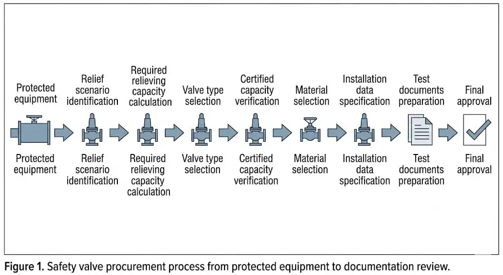
safety valve procurement workflow from protected equipment and relief scenario through required capacity valve type materials testing documentation and approval
Procurement should begin with the protected equipment and governing relief scenario, then proceed through required capacity, valve configuration, materials, installation conditions, evidence review and final acceptance.

Scope and page role: This page covers RFQ preparation, technical-bid evaluation, certificate scope, purchase-order hold points and pre-shipment acceptance. Use the Safety Valve Selection Guide for the overall engineering decision, the Sizing and Certified Capacity Guide for flow and orifice review, the RFQ Datasheet Guide for line-by-line data preparation, and the Resources or Knowledge Center for current document navigation.

Why Safety Valve Procurement Needs Engineering Review

Safety valve procurement needs engineering review because the purchase decision affects pressure protection, not only piping fit. A quotation that matches the inlet flange and pressure class may still be technically unacceptable if the valve does not satisfy the required relieving capacity, material compatibility, back pressure condition or documentation requirement.

A buyer may ask for “a 2-inch safety valve, 10 bar set pressure, carbon steel body.” That information is not enough for engineering selection. The supplier still does not know the protected equipment, MAWP, governing relief scenario, required relieving capacity, medium, relieving temperature, fluid state, back pressure, outlet destination, seat tightness requirement or applicable standard.

Three procurement principles should be clear before any order is placed:

  • Connection size confirms mechanical fit, not relieving capacity.
  • Set pressure confirms when the valve starts to open, not whether it can relieve enough flow.
  • Pressure rating confirms mechanical pressure boundary, not service suitability for the actual medium and installation.

An illustrative replacement case is a valve ordered with the same inlet and outlet size as the original valve. The new valve bolts onto the existing nozzle without difficulty, but the orifice designation and certified relieving capacity are different from the original design basis. If the certified capacity is lower than the required relieving load, the valve is not an equivalent replacement even though it looks correct on the piping.

This is why safety valve procurement should start from the protection requirement, not from the catalog model. The correct procurement sequence is:

protected equipment → relief scenario → required relieving capacity → valve type → certified capacity → material selection → installation data → test documents → final approval

If this sequence is reversed, the valve may look acceptable on a quotation but fail during technical review, inspection or operation.


Quick Procurement Checklist Before Requesting a Quote

Before requesting a safety valve quotation, the buyer should prepare enough technical data for the supplier to make a meaningful recommendation. If the RFQ contains only valve size, pressure rating and material, the response may be a commercial quote rather than an engineering selection.

Data Item Why It Matters
Protected equipment Defines the pressure boundary, code basis and protection duty.
MAWP and design pressure Identify the protected-equipment pressure boundary and should be stated separately where the equipment documentation distinguishes them.
Operating pressure Checks the margin below set pressure and leakage risk.
Set pressure Defines when the valve starts to open under specified conditions.
Relief scenario Identifies the governing case used for capacity selection.
Required relieving capacity Confirms the minimum flow the valve must discharge to protect the system.
Medium Affects sizing, valve type, trim material, seat design and corrosion risk.
Fluid state Gas, steam, liquid, two-phase or flashing flow changes the selection basis.
Relieving temperature Affects body, trim, spring, bellows and seat material limits.
Back pressure Affects capacity, opening stability, blowdown and reseating behavior.
Valve type Spring-loaded, balanced bellows and pilot-operated valves have different limits.
Material requirement Prevents corrosion, erosion, sticking, leakage and premature failure.
Seat type Soft seat and metal seat have different leakage, temperature and chemical limits.
Applicable standard Defines sizing, testing, installation, repair and documentation expectations.
Testing requirement Confirms set pressure, shell or pressure-boundary testing, seat tightness and inspection records.
Allowable overpressure / accumulation basis Connects valve sizing and relieving pressure to the protected equipment’s permitted temporary pressure rise.
Effective orifice / designation Identifies the internal rated flow area; it cannot be inferred from the inlet connection.
Superimposed and built-up back pressure Supports valve-type, capacity, blowdown, CDTP and installed-stability review.
Supplier deviations and exclusions Prevents unlisted changes to capacity basis, materials, tests, markings or document scope.
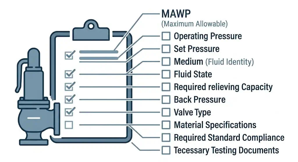
safety valve RFQ data checklist covering MAWP set pressure relief scenario required capacity fluid back pressure materials tests and documents
A complete RFQ should separate process and equipment data, pressure terms, required and certified capacity, back pressure, valve type, materials, testing, deviations and document requirements.

The items that should never be guessed are required relieving capacity, fluid state at relieving conditions, back pressure, material compatibility and certification basis. If these values are unknown, the quotation should be treated as preliminary.

Procurement warning: If the buyer cannot provide the governing relief scenario and required relieving capacity, the supplier can quote only a preliminary configuration. A valve that matches the connection size cannot be confirmed as suitable for pressure protection until the load, fluid state, relieving conditions and back-pressure basis are approved.


Process and Equipment Data Buyers Must Confirm

The first part of a safety valve RFQ should define what the valve is protecting. The protected equipment determines the pressure boundary, code requirement and credible overpressure scenarios.

Protected Equipment and MAWP

The RFQ should clearly state the protected equipment, such as a pressure vessel, boiler, air receiver, heat exchanger, compressor package, LPG tank, separator, reactor, filter, pump discharge line or blocked-in liquid section.

The buyer should identify MAWP, design pressure, design temperature, normal and maximum operating pressure, and normal operating temperature as separate fields where the equipment documentation uses them separately. MAWP and design pressure should not be treated as automatically interchangeable. These values establish the protected pressure boundary, the set-pressure review basis and the operating margin below the valve’s opening region.

Set pressure should be established against the protected equipment’s applicable pressure limit and code arrangement. Do not apply a universal rule that permits every safety valve to be set above MAWP. Boiler, pressure-vessel, multiple-device and supplemental-protection arrangements can have different requirements.

For pressure vessels, ASME BPVC Section VIII Division 1 is a common code direction because it covers rules for construction of pressure vessels, including design, fabrication, inspection, testing and certification. The actual code basis should still be confirmed by the project specification, owner requirement and local jurisdiction.

Operating Pressure and Set Pressure

Operating pressure and set pressure should both be provided. Operating pressure shows how close the system normally runs to the valve opening point. Set pressure defines when the valve starts to open under specified test conditions.

If operating pressure is too close to the valve’s opening region, the valve may simmer, weep, leak or cycle during normal pressure fluctuation. This is especially important for compressed-gas systems, steam headers, reciprocating equipment and pressure-regulator downstream systems. There is no single operating-margin percentage suitable for every valve; the acceptable separation depends on valve design, seat construction, process stability, fluid cleanliness, temperature, back pressure, manufacturer data and the applicable code or owner requirement.

Set pressure should not be increased casually to stop leakage. If the set pressure is changed without engineering review, the protected equipment may no longer be protected within its intended pressure boundary. For detailed pressure terminology, read our Safety Valve Set Pressure, Overpressure and Blowdown Explained.

Pressure-term boundary: Set pressure defines the specified opening-response point. Overpressure is referenced to set pressure during relief. Accumulation is referenced to the protected equipment’s MAWP or applicable allowable pressure limit. Blowdown is the difference between set pressure and reseating pressure. These terms should be stated separately in the engineering basis and should not be collapsed into one generic “pressure allowance.”

Relief Scenario and Required Relieving Capacity

The buyer should identify the credible relief scenario used for sizing. Common scenarios include blocked outlet, external fire, thermal expansion of blocked-in liquid, control valve failure, pressure regulator failure, heat exchanger tube rupture, cooling failure, gas blow-by and process upset.

Normal operating flow should not be used as the relief flow unless it is proven to be the governing relief case. In many real projects, the largest required relieving capacity comes from fire exposure, blocked outlet, regulator failure or tube rupture, not from normal operation.

A common procurement error is asking for a safety valve using only “line size and set pressure.” In an illustrative procurement review, the quoted valve had the correct connection and pressure rating, but the buyer had not provided the fire-case required relieving load. After capacity review, the valve was found to be smaller than required. The correction was to recalculate the relief case and request a valve with certified capacity equal to or greater than the required relieving load.

For capacity-related procurement review, read our Safety Valve Sizing and Certified Relieving Capacity Guide.

Capacity hold point: Do not accept “capacity available on request,” “suitable for NPS 2,” or a catalog maximum as evidence that the offered valve protects the equipment. The supplier response should identify the selected model, effective orifice, capacity medium, relieving pressure and temperature, applicable coefficient or certification basis, and the resulting capacity for the approved case.

Fluid State at Relieving Conditions

The RFQ should describe the fluid state at relieving conditions, not only at normal operating conditions. Gas, steam, liquid, two-phase and flashing flow require different sizing and review methods.

A liquid may flash when pressure drops. A gas may carry liquid droplets. Steam may be saturated or superheated. A clean process fluid on the datasheet may become contaminated after years of operation due to corrosion products, scale, fouling or process carryover.

Fluid Condition Procurement Impact
Steam Check temperature, trim material, spring exposure, drainage and discharge reaction force.
Clean gas May support spring-loaded or pilot-operated designs depending on pressure, capacity and shutoff needs.
Dirty or wet gas Can create pilot line blockage, guide sticking, seat leakage or unstable response.
Liquid Requires suitable valve design, density and viscosity review, and discharge destination check.
Two-phase or flashing flow Requires careful engineering review and should not be treated as simple gas or liquid service.
Corrosive fluid Requires trim, nozzle, disc, guide, spring, bellows and seat material review.

Terminology note: In common process-industry usage, a safety valve is often associated with rapid opening in steam, gas or vapor service, while a relief valve is often associated with more proportional liquid service. A safety relief valve may be designed for compressible or incompressible duty. The RFQ should not rely on the abbreviation PSV or PRV alone; it should define the fluid, phase, opening characteristic and certification basis required for the actual service.


Certified Capacity, Orifice Area and Nameplate Data

Certified relieving capacity is one of the most important procurement approval items. It confirms whether the valve has verified relieving capability for the stated condition. Connection size alone cannot prove protection capability.

safety valve nameplate capacity certificate and datasheet review showing serial number set pressure effective orifice certified capacity and code marking
The approved datasheet, physical nameplate, effective orifice, capacity evidence and order-specific records should refer to the same valve configuration and serial identity.

Why Certified Capacity Matters More Than Nominal Size

Two safety valves may have the same inlet connection but different orifice areas and certified capacities. A buyer who approves a valve by inlet size alone may unintentionally reduce the actual pressure protection capability of the system.

The selected valve should have certified relieving capacity equal to or greater than the required relieving capacity under the specified service basis. If the capacity basis is air, steam or water, the buyer should confirm whether it applies directly to the actual process fluid or whether engineering conversion or manufacturer confirmation is required.

API 520 Part I is a key standard direction for sizing and selection of pressure-relieving devices in refinery service. For procurement, it supports the need to check sizing basis and capacity data before approval.

Orifice Designation and Rated Capacity

The RFQ and quotation should clearly identify the orifice designation or effective discharge area. This is especially important when replacing an existing valve. Same body size or same inlet flange does not necessarily mean same orifice.

For flanged steel pressure relief valves, API 526 is commonly associated with purchase specification details such as orifice designation and area, valve size, pressure rating, materials and dimensional references. The project specification should confirm whether API 526 is required for the purchased valve.

What to Check on the Valve Nameplate

The valve nameplate should match the datasheet, capacity certificate and test documents. Any mismatch should be clarified before shipment or installation.

Nameplate Item Why It Matters
Manufacturer Confirms valve source and traceability.
Model / type Confirms valve design and construction.
Serial number Links the physical valve to certificates and test records.
Set pressure Confirms the adjusted opening pressure.
Orifice designation Confirms internal flow area basis.
Certified capacity Confirms verified relieving capability.
Capacity medium Shows whether the capacity is based on air, steam, water or another basis.
Temperature basis Affects capacity, material and seat suitability.
Code mark or certification mark Supports compliance when required by the project or jurisdiction.
Inlet / outlet size and rating Confirms mechanical compatibility with the piping system.

Capacity Certificate vs Datasheet

A datasheet states the selected valve configuration. A capacity certificate supports the verified relieving capability. A test report confirms specific testing performed on the supplied valve. These documents are related, but they are not the same.

Before purchase approval, the buyer should check that the datasheet, nameplate, capacity certificate and quotation all refer to the same valve type, model, set pressure, orifice, capacity basis and material configuration.


Valve Type Selection: Spring-Loaded, Balanced Bellows or Pilot-Operated

The RFQ should not simply state “safety valve” if the service condition requires a specific design. Spring-loaded, balanced bellows and pilot-operated safety valves respond differently to back pressure, medium cleanliness, seat tightness needs and maintenance conditions.

When a Spring-Loaded Safety Valve Is Suitable

A spring-loaded safety valve is often suitable for general steam, air, utility and many standard pressure vessel applications. It is usually simpler to inspect, repair and recalibrate than a pilot-operated valve.

It may be preferred when the service is dirty, mildly contaminated or maintenance resources are limited. However, conventional spring-loaded valves can be sensitive to back pressure, so discharge system data should still be reviewed.

When a Balanced Bellows Design Should Be Considered

A balanced bellows safety valve may be considered when back pressure would negatively affect a conventional spring-loaded valve. The bellows helps reduce the effect of back pressure on valve operation, but it is also a critical component that must be compatible with temperature, corrosion and fatigue conditions.

The RFQ should state whether the discharge system has constant or variable back pressure. The supplier should confirm allowable back pressure, bellows material, bonnet vent requirements and inspection needs.

When a Pilot-Operated Safety Valve May Be Suitable

A pilot-operated safety valve may be suitable for clean high-pressure gas service, large relieving capacity, tight shutoff requirements or systems operating close to set pressure. It should not be selected blindly for dirty, wet, sticky, crystallizing, polymerizing or particle-containing service.

In an illustrative service example, a pilot-operated safety valve was selected for a high-pressure gas system because the operating pressure was close to set pressure and tight shutoff was important. After installation, the valve response became unstable. The root cause was liquid carryover and fine particles entering the pilot sensing line. The correction included cleaning the pilot circuit, reviewing separation and drainage, checking sensing line arrangement and confirming the manufacturer’s service recommendations.

For detailed valve type comparison, read our Spring-Loaded Safety Valve vs Pilot-Operated Safety Valve.

Service Condition Procurement Direction
General steam or air Spring-loaded valve is often practical, with temperature and drainage review.
Dirty or particle-containing gas Avoid blind pilot-operated selection; review spring-loaded or balanced design.
Clean high-pressure gas Pilot-operated valve may be suitable if certified capacity and back pressure limits are confirmed.
High variable back pressure Balanced bellows or suitable pilot-operated design may be considered.
Poor maintenance access Simple spring-loaded design may reduce lifecycle risk.
Corrosive service Valve type alone is not enough; material and trim must be reviewed.

Back Pressure and Installation Data Required for Procurement

Back pressure and installation data should be included before the valve is purchased. If these items are ignored during procurement, the valve may chatter, lose effective capacity or reseat poorly after installation.

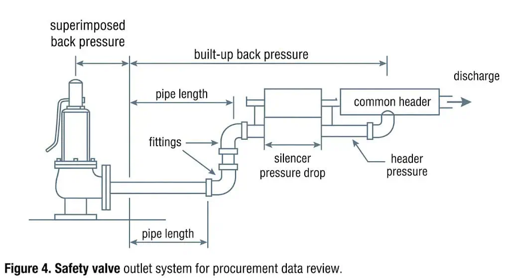
back pressure and installation data required before safety valve procurement including superimposed built-up pressure outlet piping header silencer drainage and inlet loss
Superimposed back pressure, built-up back pressure, outlet piping, silencers, common headers, drainage and reaction loads should be reviewed before purchase.

Superimposed and Built-Up Back Pressure

Superimposed back pressure is pressure already present at the valve outlet before the valve opens. Built-up back pressure is generated after the valve opens and flow passes through the outlet piping, silencer, discharge header or flare system.

The buyer should provide both values if available. If they are not known, the RFQ should state the discharge destination and provide outlet pipe details so the supplier or engineering team can review whether the selected valve type is suitable.

Outlet Pipe, Silencer and Discharge Header

The RFQ should describe the outlet pipe size, length, number of elbows, reducers, silencers, mufflers, tail pipe arrangement, common header pressure and flare or vent system condition.

One common problem occurs when a silencer is added after the valve has been selected. The original selection may assume atmospheric discharge, but the silencer adds outlet resistance and increases built-up back pressure. The valve may pass a shop test but chatter during actual relief. The correction is to recalculate outlet resistance, review manufacturer allowable back pressure and confirm whether the original valve type remains suitable.

API 520 Part II is the relevant API standard direction for installation considerations and engineering analysis for pressure-relieving devices.

Inlet Pressure Loss and Installation Orientation

The inlet line should allow pressure to reach the valve without excessive loss. Long inlet lines, undersized nozzles, restrictions, elbows or isolation valves can contribute to instability. Excessive inlet pressure loss can cause rapid cycling or chatter.

The RFQ should also state whether the valve will be installed vertically or in another orientation. Most spring-loaded safety valves are intended for vertical installation with the spindle upright unless the manufacturer permits another arrangement.

For detailed installation review, read our Safety Valve Installation Guide.

Installation Data Why It Matters in Procurement
Outlet destination Atmosphere, header, flare and closed vent systems behave differently.
Superimposed back pressure Affects opening behavior and force balance.
Built-up back pressure Affects lift, capacity, blowdown and reseating.
Outlet pipe size and length Determines pressure drop and reaction force.
Elbows and fittings Add resistance and turbulence.
Silencer or muffler Can increase outlet resistance and back pressure.
Common header May create variable back pressure during simultaneous relief.
Inlet line configuration Excessive inlet pressure loss can cause unstable operation.
Drainage and low points Important for steam, condensate, freezing and corrosive service.

Material, Trim and Seat Design Checklist

Material review should not stop at body material. Many safety valve failures start at the nozzle, disc, guide, spring, bellows or seat. These components are exposed to pressure, temperature, corrosion, erosion, deposits and repeated opening events.

Body and Bonnet Material

The body and bonnet material should match pressure rating, temperature range, external environment and project specification. Common materials include carbon steel, stainless steel, alloy steel, bronze or special alloys depending on service.

Carbon steel may be acceptable for many general services, but it may not be suitable for corrosive media, low-temperature service or specific project requirements. Stainless steel may improve corrosion resistance, but the exact grade should be confirmed against the fluid chemistry.

Nozzle, Disc and Guide Material

The nozzle and disc form the seating surface. If these surfaces corrode, erode, wire-draw or become damaged by particles, leakage can increase even when set pressure remains correct.

In chloride-containing or acidic service, early leakage may be caused by localized corrosion on the nozzle or disc seating line. The correction is not only to lap the seat. The trim material and corrosion mechanism must be reviewed.

Spring and Bellows Material

The spring must retain its mechanical behavior under the actual temperature and environmental condition. High temperature, corrosion and external exposure can affect spring performance over time.

If a balanced bellows valve is selected, the bellows material should be compatible with the process, discharge system and temperature. Bellows fatigue, corrosion and blocked bonnet vent conditions should be considered during procurement.

Soft Seat vs Metal Seat

Soft seats can provide better tightness in clean and temperature-compatible service, but they have chemical and temperature limitations. Metal seats are often more suitable for high-temperature steam, abrasive service and severe conditions, but seat tightness depends on surface finish, loading, lapping quality and test requirements.

Component Procurement Check
Body Pressure rating, temperature, corrosion and external environment.
Bonnet Open or closed bonnet, service temperature and venting needs.
Nozzle Corrosion, erosion, wire drawing and seat leakage risk.
Disc Seat contact, erosion resistance and compatibility with medium.
Guide Sticking, galling, fouling and alignment risk.
Spring Temperature exposure, corrosion and relaxation risk.
Bellows Back pressure service, corrosion, fatigue and vent condition.
Seat Soft seat or metal seat, leakage class, temperature and chemical limits.

For sour service, NACE MR0175 / ISO 15156 may be relevant to material selection. It should only be specified when sour service applies, not inserted as a general requirement for every safety valve.


Certificate Scope and Traceability: What Each Document Actually Proves

A certificate image, website badge or generic sample should never be accepted as proof that every valve, size, material, manufacturing site or order is covered. Procurement should identify whether each document applies to the legal manufacturing entity, an approved quality system, a product design, a tested range, a material heat or the individual supplied valve.

Company or Management-System Certificate

Applies to the named legal entity, location and stated quality-management or manufacturing scope. It does not automatically certify every safety-valve design, code mark, capacity or material option.

Product, Design or Type-Test Certificate

Applies only to the product family, design, size or pressure range, medium, standard edition and extension rules stated by the issuing body. The quoted valve must fall inside that scope.

Certified Capacity Evidence

Supports flow capability for a defined model, effective orifice, pressure basis, test medium and configuration. It does not prove that the buyer’s required relief load or scenario is correct.

Material Certificate

Links a stated material grade and heat, lot or batch to a component or manufacturing record. Traceability should continue from the certificate to the bill of materials, component and valve serial number where required.

Order-Specific Test Report

Records a specified test on the individual valve or production order, such as pressure-boundary testing, set-pressure calibration or seat tightness. Each report proves only the test and condition it identifies.

Repair or Recertification Record

Identifies the as-found condition, parts replaced, approved repair scope, as-left setting, seat test, lock or seal status and repair authorization where applicable.

Review the exact document title, issuing organization, certificate or report number, revision or validity status, product scope, referenced standard and connection to the supplied serial number. Use the Safety Valve Resources Center and Safety Valve Knowledge Center for current resource navigation rather than relying on an unverified deep-link path.

Controlled-original rule: A public preview, redacted sample or sales attachment is not automatically the controlled project document. The purchase order should define whether the buyer requires an original digital file, authenticated copy, inspection release, electronic verification or a document linked to the individual serial number.
Evidence hierarchy: A datasheet describes the selected configuration; a relief calculation defines the required duty; certified capacity supports flow capability; a nameplate identifies the physical valve; material certificates support traceability; test reports document specific tests; and a repair record documents work performed. Procurement approval should reconcile all of them.

Testing and Inspection Documents to Request from the Supplier

A complete safety valve order should define the required document package before purchase. Missing documents can delay inspection, installation, commissioning or future repair review.

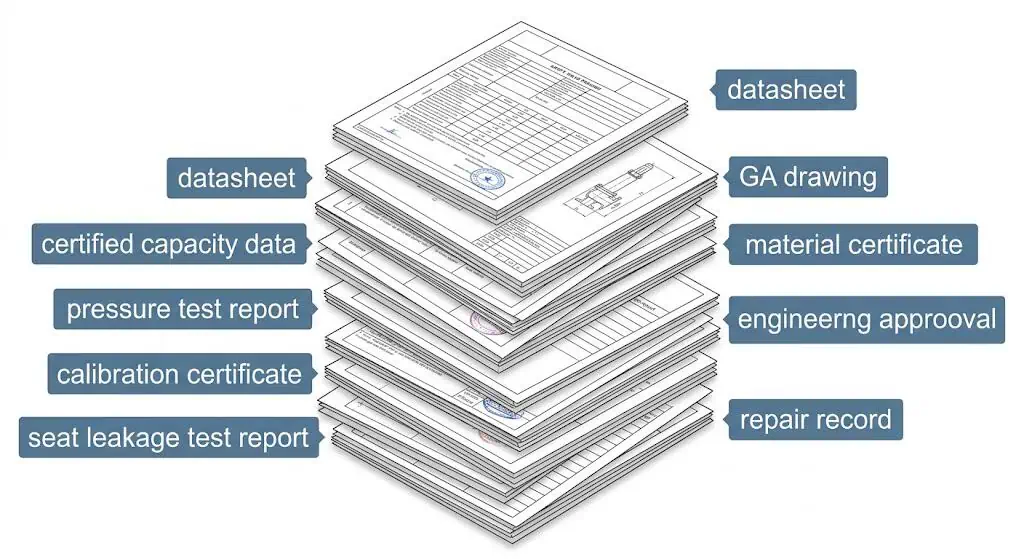
safety valve supplier document package including approved datasheet capacity evidence material certificates pressure test calibration seat tightness nameplate and repair records
Procurement approval should reconcile the technical datasheet, capacity evidence, drawings, material traceability, test reports, marking and supplier deviations.

Datasheet and General Arrangement Drawing

The datasheet should confirm valve type, model, inlet and outlet size, pressure rating, set pressure, orifice, certified capacity, material, seat type, code basis and testing scope. The general arrangement drawing should show dimensions, connection details, flow direction, lifting lever or cap arrangement and installation envelope.

Certified Capacity Data

The capacity data should show the certified relieving capacity, capacity basis, set pressure, relieving pressure, orifice designation and valve model. It should be consistent with the required relieving load and procurement datasheet.

Material Certificates

Material certificates should confirm the body, bonnet, nozzle, disc, guide, spring, bellows and seat materials where required by the project specification. For corrosive or sour service, material traceability is more than an administrative requirement; it affects long-term reliability and compliance.

Set Pressure Calibration Certificate

The calibration certificate should confirm the actual set pressure, test medium, pressure reference, ambient or service correction basis and test condition. Where cold differential test pressure is applicable, the certificate and datasheet should identify the approved correction for service temperature and constant superimposed back pressure rather than using an undocumented shop adjustment.

After repair or adjustment, a safety valve should not be returned to service without proper recalibration, locking or sealing, tagging and traceable documentation. A calibration certificate proves the as-left opening setting under the stated test basis; it does not prove certified flow capacity or installed-system stability.

Seat Leakage Test Report

If seat tightness is important, the RFQ should state the test method, medium, pressure, acceptance criterion and reporting requirement. API 527 is commonly referenced for applicable metal- and soft-seated pressure relief valves, including conventional, bellows and pilot-operated designs.

Test-evidence boundary: Set-pressure calibration confirms the adjusted opening point. Seat-tightness testing confirms leakage under a specified closed-valve test condition. Pressure-boundary testing confirms shell integrity. Certified capacity data confirms flow performance for a defined configuration. Procurement should request the evidence actually required and should not use one report as a substitute for another.

Repair and Recertification Records

If the valve is repaired rather than new, the buyer should request repair records, replaced parts list, set pressure calibration record, seat leakage test record and recertification documents as applicable.

The National Board VR Certificate of Authorization is relevant where pressure relief valve repair authorization is required by code, jurisdiction, owner specification or project requirement.

Document What It Confirms
Valve datasheet Selected configuration and technical basis.
General arrangement drawing Dimensions, connection and installation envelope.
Certified capacity data Verified relieving capability.
Material certificate Material traceability and compatibility.
Pressure test report Body and pressure boundary testing.
Set pressure calibration certificate Actual opening pressure adjustment.
Seat leakage test report Seat tightness performance.
Nameplate information Traceability and field identification.
Installation manual Required orientation, piping and maintenance precautions.
Repair record, if applicable Repair route, replaced parts, recalibration and resealing record.

Standards and Compliance Checks Before Purchase

Standards should be connected to a specific procurement decision rather than listed as generic evidence of quality. The purchase order should identify the governing equipment code, product or sizing standard, required edition where applicable, code mark, capacity basis, testing scope, inspection route and repair requirements.

Standard / Code Direction Procurement Role and Boundary Official Reference
ASME BPVC Section XIII Provides the ASME overpressure-protection rules framework for pressurized equipment. It should be read with the construction code applicable to the protected boiler, pressure vessel or piping system. ASME official page
ASME BPVC Section VIII, Division 1 Provides pressure-vessel construction, inspection, testing and certification context. It does not replace the valve sizing, installation or supplier-document review. ASME official page
ASME BPVC Section I Applies when the protected equipment is a power boiler or related boiler component under that code route. A general process-valve quotation should not be accepted as an automatic boiler-safety-valve equivalent. ASME official page
API 520 Part I Supports sizing and selection of pressure-relieving devices in refinery and related applications. Procurement should connect the required load, relieving conditions and selected capacity basis. API official page
API 520 Part II Supports installation review, including inlet and outlet conditions and applicable engineering analysis. It is not a certified-capacity or seat-tightness standard. API official page
API 521 Supports definition of pressure-relief and depressuring scenarios, flare or vent-system conditions and system-level disposal review. API official page
API 526 Standardizes key purchase dimensions and letter-designated effective orifices for applicable flanged steel pressure relief valves. It does not calculate the required relief load or prove service suitability. Confirm the required project edition and product scope.
API 527 Defines seat-tightness methods and acceptance criteria for applicable metal- and soft-seated pressure relief valves. It does not prove required or certified capacity. API official publication page
API RP 576 Supports inspection, condition assessment, maintenance and failure evaluation of pressure-relieving devices. It is relevant to lifecycle and repaired-valve procurement. Confirm the edition required by the owner or inspection plan.
ISO 4126-1 Provides general product requirements for safety valves irrespective of fluid. ISO identifies it as a product standard, not an application-selection standard. ISO official page
ISO 4126-4 Provides product requirements for pilot-operated safety valves. Pilot suitability still depends on the medium, pilot exhaust, sensing arrangement, back pressure and maintenance capability. ISO official page
National Board / NBIC / VR May govern installation, in-service inspection and authorized repair depending on jurisdiction and owner requirements. VR authorization is relevant where recognized pressure-relief-valve repair is required. National Board official page
NACE MR0175 / ISO 15156 Relevant only when sour-service material requirements apply. It should not be inserted into every safety-valve purchase specification by default. Confirm the project’s sour-service basis and material limits.
Compliance boundary: “ASME,” “API,” “ISO,” “PED,” “CE” or “National Board” should not be accepted as a complete supplier statement. Require the exact standard, edition or conformity route, product scope, marking, certificate number and manufacturing entity that apply to the offered valve.

How to Review a Safety Valve Quotation

A safety valve quotation should be reviewed technically before price comparison. A lower-price quotation may be incomplete if it excludes capacity certification, material certificates, seat leakage testing, calibration documents or special material requirements.

Check Whether the Quotation Matches the RFQ Data

First confirm that the quotation reflects the same protected equipment data, set pressure, required relieving capacity, medium, relieving temperature and back pressure condition provided in the RFQ. If the supplier changed assumptions, those changes should be clearly identified.

Compare Certified Capacity, Not Only Model Number

Two quotations may show similar models or the same inlet size, but the certified capacity may differ. The technical review should compare orifice designation, capacity basis, certified capacity and set pressure before comparing price.

Confirm Valve Type and Material Details

The quotation should clearly state whether the valve is conventional spring-loaded, balanced bellows or pilot-operated. It should also identify body material, trim material, spring material, bellows material and seat material where applicable.

Clarify Exclusions Before Purchase

Common exclusions include special testing, material certificates, third-party inspection, lifting lever, gag, special painting, spare parts, installation manual, seat leakage test report, calibration certificate and repair documentation.

Require a Supplier Deviation and Assumption Register

Every bidder should identify deviations, substitutions, exclusions and assumptions in one controlled list. Silence should not be treated as acceptance of every purchase-order requirement. The register should identify the affected datasheet line, supplier proposal, technical consequence and whether buyer approval is required.

Common hidden deviation: The quotation states the requested inlet and outlet sizes but substitutes a different effective orifice, seat material, spring range, bellows material, capacity basis, code mark or document scope. These differences can change pressure protection even when the commercial description looks similar.
Quotation Item Review Question
Valve model Does it match the service and valve type requirement?
Inlet / outlet size Does it fit the piping and match the selected design?
Pressure class Is it suitable for design pressure and temperature?
Set pressure Does it match the approved protection basis?
Orifice designation Does it support the required capacity?
Certified capacity Is it equal to or greater than required relieving capacity?
Capacity basis Air, steam, water or actual process condition?
Material Are body, trim, spring, bellows and seat materials defined?
Testing scope Are pressure test, calibration and seat leakage test included?
Documents Are datasheet, certificates and manuals included?
Delivery Does lead time include approval drawings, testing, third-party inspection, document review and release?
Supplier assumptions Are the relief scenario, fluid phase, relieving conditions, back pressure and capacity conversions identical to the RFQ basis?
Deviations and substitutions Are all material, design, code, marking, testing and document differences explicitly listed for approval?
Lifecycle support Are approved spare parts, repair instructions, calibration support and maintenance requirements available?

In an illustrative quotation review, the lower-price offer looked attractive because the valve size and pressure rating matched the RFQ. A closer review showed that seat leakage testing and material certificates were excluded. For a clean gas system operating close to set pressure, those exclusions were not acceptable. The buyer revised the technical requirement and compared only complete quotations.


Pre-Shipment Inspection Checklist

Pre-shipment inspection helps confirm that the supplied valve matches the approved technical requirement before it reaches site. This is especially important for shutdown replacement, code-controlled equipment and overseas procurement.

Nameplate Check

The inspector should confirm that the nameplate matches the approved datasheet and certificate. Set pressure, serial number, model, orifice, capacity, inlet size, outlet size and code marking should be checked.

Calibration and Seal Check

The set pressure calibration record should be reviewed. If the valve has been adjusted, the seal and tag should match the final calibrated condition. A valve with broken or missing seals should be investigated before installation.

Visual and Mechanical Check

Check the flange faces, threaded connections, lifting lever, cap, drain plug, shipping protection, paint condition and flow direction. Confirm that no foreign material is present in the inlet or outlet.

Document Package Review

The final document package should be complete before shipment. Missing documents can delay installation, commissioning or inspection acceptance.

Pre-Shipment Item Confirmed
Nameplate matches approved datasheet
Serial number matches certificates
Set pressure calibration record available
Certified capacity data available
Seat leakage test report available if required
Material certificates available
Flange faces protected
Inlet and outlet are clean
Seal and tag condition checked
Installation manual included
Supplier deviations closed or approved
Capacity basis matches the approved relief case
Material and certificate scope verified
Shipping gag or transit restraint status identified
Bonnet vent, drain and pilot connections protected but not incorrectly plugged

Common Procurement Mistakes That Cause Safety Valve Problems

Most safety valve procurement mistakes are caused by incomplete data, not by lack of suppliers. The following problems are common in technical bid reviews and field failure investigations.

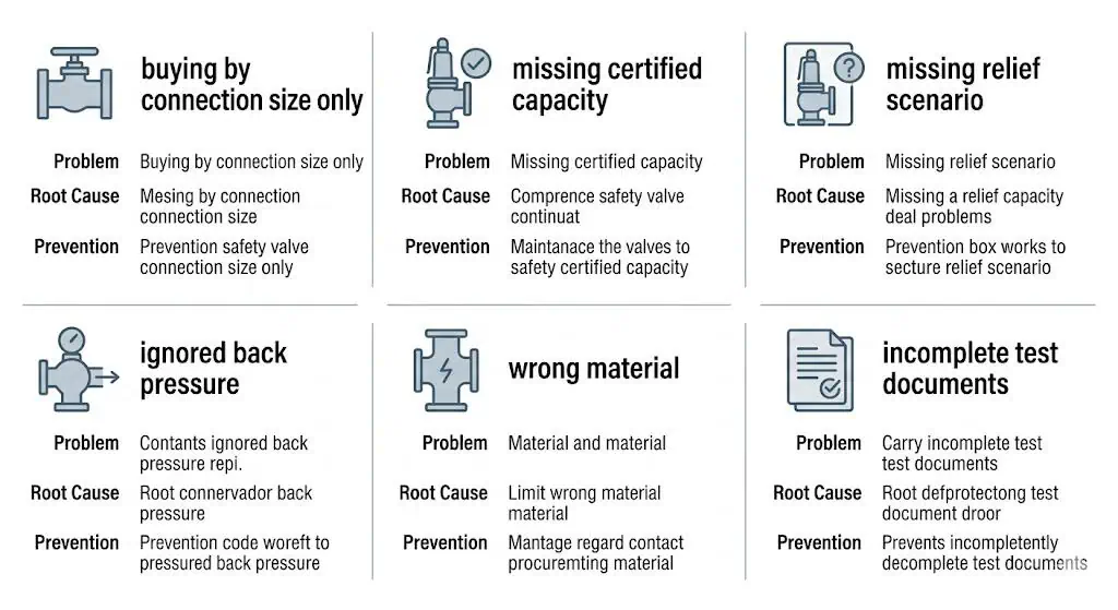
common safety valve procurement mistakes including connection size only insufficient capacity ignored back pressure wrong materials pilot contamination and missing documents
Most procurement failures begin with incomplete relief data, unreviewed supplier assumptions, mismatched certificate scope or missing acceptance evidence.

Buying by Connection Size Only

A valve with the same inlet size may have a different orifice area and certified relieving capacity. This can happen during replacement if the original datasheet and capacity basis are not reviewed.

Problem: Same connection size replacement was approved.

Root cause: Orifice designation and certified capacity were not compared.

Correction / prevention: Require certified capacity data and confirm equivalence before purchase.

Not Providing the Relief Scenario

A supplier cannot confirm required capacity without knowing the governing relief scenario. Fire case, blocked outlet, regulator failure and tube rupture may produce very different required loads.

Problem: Valve was quoted from normal operating data.

Root cause: Governing relief case was not included in the RFQ.

Correction / prevention: Provide relief scenario and required relieving capacity before quotation approval.

Ignoring Back Pressure

Back pressure can affect valve lift, capacity, stability and reseating. A valve that passes shop testing may chatter after installation if the outlet system creates excessive built-up back pressure.

Problem: Valve chattered after installation.

Root cause: Silencer and common header pressure were not included in procurement review.

Correction / prevention: Provide outlet system data and confirm allowable back pressure before ordering.

Choosing Pilot-Operated Valves for Dirty Service

Pilot-operated valves can be effective in clean gas service, but dirty gas, liquid carryover or particles can affect pilot stability.

Problem: Pilot-operated valve response became unstable.

Root cause: Wet gas and fine particles contaminated the pilot sensing line.

Correction / prevention: Review medium cleanliness, separation, drainage, filtration, sensing line arrangement and maintenance access.

Ignoring Material Compatibility

Corrosion at the nozzle and disc seating surface can cause early leakage. Body material alone is not enough. Trim, spring, guide, bellows and seat materials should be reviewed.

Problem: Safety valve leaked shortly after service exposure.

Root cause: Chloride or acidic medium damaged seating surfaces.

Correction / prevention: Confirm trim material compatibility before purchase.

Accepting Incomplete Test Documents

A valve may be delivered with a datasheet but without capacity certificate, calibration certificate, seat leakage report or material certificate. Missing documents can become a problem during inspection, commissioning or future repair.

Problem: Valve could not be accepted at site.

Root cause: Required test documents were not specified in the purchase order.

Correction / prevention: Define document package in the RFQ and quotation before purchase.

Returning Repaired Valves Without Recalibration

A repaired valve should not be returned to service only because it looks clean. Set pressure, seat tightness, reseating behavior and seal condition should be verified.

Problem: Repaired valve opened at a shifted pressure.

Root cause: Repair was completed without proper recalibration and documentation.

Correction / prevention: Require repair records, calibration certificate, seat leakage report and resealing confirmation.


When Safety Valve Procurement Approval Must Be Held

Do not release the purchase order or shipment while any of the following points remains unresolved:

Unknown Required Capacity

The valve cannot be proven adequate for the governing relief case.

Unclear Fluid Phase

Flashing, two-phase or wet service may invalidate a single-phase assumption.

Unresolved Back Pressure

Valve type, capacity, CDTP basis and stability cannot be confirmed without the downstream condition.

Certificate Scope Mismatch

The document does not cover the quoted design, size, material, code route or manufacturing entity.

Datasheet and Nameplate Conflict

Set pressure, model, effective orifice, serial number, marking or material information does not agree.

Unapproved Material Substitution

The proposed alternative changes corrosion, temperature, leakage, fatigue or compliance performance.

Missing Required Test Evidence

The purchase order or inspection plan requires records that are not available or not linked to the supplied valve.

Unlisted Supplier Deviations

The quotation appears compliant but uses different technical assumptions, exclusions or substituted components.

Final Safety Valve Procurement Checklist

The following checklist can be used before issuing an RFQ, approving a quotation or accepting a safety valve before shipment.

Checklist Item Confirmed
Protected equipment identified
MAWP and design pressure basis confirmed
Operating pressure confirmed
Set pressure confirmed
Relief scenario confirmed
Required relieving capacity confirmed
Certified capacity verified
Orifice designation checked
Medium and fluid state confirmed
Relieving temperature confirmed
Back pressure reviewed
Valve type selected and justified
Body and trim material confirmed
Seat type confirmed
Standard / code basis confirmed
Test reports required in purchase order
Nameplate data checked
Installation manual requested
Repair / VR documents requested if applicable
Final document package reviewed before shipment
Allowable overpressure / accumulation basis confirmed
CDTP or test correction basis confirmed if applicable
Inlet pressure loss and outlet-system condition reviewed
Supplier deviations, substitutions and exclusions approved
Certificate scope linked to offered model and manufacturing entity
Post-repair locking, sealing and tagging requirements defined if applicable

Final buyer question: Can the offered valve discharge the approved required load under the actual medium, phase, relieving pressure and temperature, back pressure, material condition and installation arrangement—and can the supplier prove that configuration with consistent, traceable documents?

If the answer is unclear, the purchase is not ready for approval. Record the unresolved item as a technical hold point rather than transferring the uncertainty to site commissioning or maintenance.

For detailed RFQ preparation, use How to Prepare a Safety Valve Datasheet for RFQ.

Related safety valve engineering guides:


Prepare a Complete Safety Valve RFQ

Send the protected equipment, relief scenario, required relieving capacity, medium and phase, relieving conditions, set pressure, back pressure, connections, materials, installation arrangement and document requirements for a technically comparable quotation.

Upload RFQ or Datasheet Request a Safety Valve Quote View Safety Valve Resources

FAQ About Safety Valve Procurement

What information is needed to buy a safety valve?

Provide the protected equipment and tag, governing relief scenario, MAWP or other allowable pressure limit, operating pressure and temperature, set pressure, allowable overpressure or accumulation basis, required relieving capacity, medium and phase at relieving conditions, relieving temperature, superimposed and built-up back pressure, valve type, effective orifice, materials, seat construction, installation data, testing, marking and document requirements.

Can I buy a safety valve by connection size only?

No. Connection size confirms the piping interface. It does not prove the effective orifice, certified relieving capacity, fluid suitability, back-pressure performance, material compatibility, opening characteristic or documentation scope.

What is the difference between required and certified relieving capacity?

Required relieving capacity is the flow demand calculated from the governing overpressure scenario. Certified or project-accepted capacity is the documented flow capability of the selected valve and configuration under a defined pressure, temperature and fluid basis. The offered capacity must satisfy the approved required load.

Why is certified relieving capacity more important than connection size?

Two valves with the same inlet and outlet connections can have different effective orifices, coefficients, lifts and certified capacities. A physically interchangeable valve can therefore provide less pressure protection than the original design.

Should back pressure be included in the RFQ?

Yes. State the superimposed back-pressure range, whether it is constant or variable, the calculated built-up back pressure at the governing relief flow, outlet piping, silencers, common-header or flare conditions and discharge destination. These conditions can affect valve type, capacity, stability, blowdown and reseating.

When should a pilot-operated safety valve be considered?

A pilot-operated design may be considered for suitable clean service where tight shutoff, operating pressure close to set pressure, large capacity or specific back-pressure performance provides a real benefit. The RFQ must also address pilot exhaust, sensing lines, condensation, freezing, fouling, seals and maintenance capability.

What materials should be specified for corrosive safety-valve service?

Review the body, bonnet, nozzle, disc, guide, spindle, spring environment, bellows, gaskets, O-rings and seat materials against the actual corrosion mechanism, pressure and relieving temperature. Body material alone does not prove trim or seal compatibility.

What documents should a safety valve supplier provide?

The required package may include the approved datasheet, general arrangement drawing, certified capacity evidence, material certificates, pressure-boundary test report, set-pressure calibration record, seat-tightness report, nameplate details, installation and maintenance instructions, inspection release, deviation register and repair records where applicable.

What should be checked on a safety valve nameplate?

Check the manufacturer, model or type, serial number, set pressure, inlet and outlet size and rating, effective-orifice or designation data where marked, certified-capacity information where required, capacity medium, code or certification marking and consistency with the approved datasheet and records.

What is the difference between a datasheet, capacity certificate and test report?

A datasheet describes the selected configuration. Capacity evidence supports the documented flow capability of a defined valve and orifice. A test report records a specific test performed on an individual valve or order. These documents are related but are not interchangeable.

Do I need a safety valve calibration certificate?

A set-pressure calibration record is normally required when specified by the purchase order, code, owner or repair program. It should identify the valve, as-left set pressure, test medium and test basis, applicable CDTP or service correction, test equipment traceability, date and seal or tag status.

Should repaired safety valves have repair and recertification documentation?

Yes. Request the as-found condition, work scope, parts replaced, approved component interchangeability, as-left set pressure, seat-tightness result, pressure test where applicable, lock or seal confirmation and recognized repair authorization such as National Board VR where required.

How should safety valve quotations be compared?

Compare every bid against the same protected-equipment data, relief scenario, required capacity, relieving conditions, back pressure, valve type, effective orifice, materials, tests, markings, documents, deviations and delivery scope before comparing price.

When should safety valve procurement approval be held?

Hold approval when the required capacity, fluid phase, relieving temperature, back pressure, effective orifice, capacity basis, material compatibility, code route, certificate scope, supplier deviations or required test evidence is unresolved.

What standards should be checked before buying a safety valve?

The applicable standards depend on the protected equipment and service. Common directions include ASME BPVC Section XIII with the relevant construction code, API 520 Parts I and II, API 521, API 526, API 527, API RP 576, ISO 4126-1, ISO 4126-4 and National Board or NBIC repair requirements where applicable.