Share your medium, set pressure, temperature, size, standard, or datasheet, and our team will review your requirement and respond with the appropriate next step.
Can a Safety Valve Replace a Relief Valve? Risks and Checks Before Replacement
A safety valve should not be treated as a direct replacement for a relief valve, and a relief valve should not be treated as a direct replacement for a safety valve, merely because their connection sizes, pressure classes, body materials, or set pressures appear similar. A substitution may be technically acceptable only after the proposed replacement …
A safety valve should not be treated as a direct replacement for a relief valve, and a relief valve should not be treated as a direct replacement for a safety valve, merely because their connection sizes, pressure classes, body materials, or set pressures appear similar. A substitution may be technically acceptable only after the proposed replacement has been verified for the actual protected equipment, governing overpressure scenario, relieving fluid and phase, opening characteristic, required relieving capacity, certified or project-accepted capacity, back pressure, materials, installation, testing, and applicable code route.
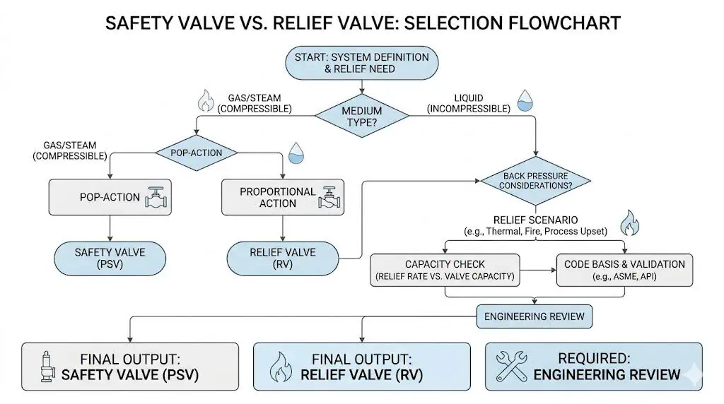
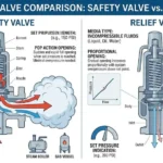
In common API and process-industry usage, a safety valve is generally associated with rapid or pop opening in steam, gas, air, or vapor service. A relief valve is generally associated with progressive or proportional opening in liquid service. This distinction is useful, but it is not an absolute global naming rule. ISO terminology and some manufacturer product families use “safety valve” more broadly, including products intended for different fluids. The actual product design, capacity certification, test basis, and application data must therefore control the replacement decision.
The most important question is not whether the new valve physically fits. The important question is whether it provides an equivalent or better pressure-protection function under the real relieving conditions. A one-for-one swap without that review can result in chatter, hydraulic shock, poor reseating, seat leakage, insufficient capacity, unstable lift, excessive back pressure, unsuitable material performance, failed inspection, or expensive field rework.
Wrong replacement can create unstable lift, flutter, chatter, or repeated cycling.
Seat leakage after operation may result from unsuitable opening behavior, blowdown, back pressure, materials, or installation—not only poor seat finishing.
Required and certified capacity can change even when the inlet and outlet sizes remain identical.
A valve can pass bench set-pressure testing and still perform poorly in the installed system.
A replacement can be mechanically interchangeable but technically or legally unacceptable.
The words PSV, PRV, safety valve, relief valve, and safety relief valve must not be used as substitutes for a complete service definition.
This page addresses a practical question engineers, buyers, inspectors, and maintenance teams often face during shutdowns, repairs, retrofits, and procurement: can one valve type replace the other without creating a new pressure-protection risk? For a broader terminology comparison, see PRV vs PSV vs safety valve vs relief valve.
When Substitution Creates Risk
Why a One-for-One Valve Swap Is Often Unsafe
A one-for-one replacement becomes unsafe when the review stops at valve size, flange class, set pressure, body material, or model appearance. Those items confirm only part of the requirement. They do not prove that the replacement valve has the correct effective orifice, certified capacity, fluid-service approval, opening characteristic, blowdown, seat design, back-pressure capability, temperature range, or code marking.
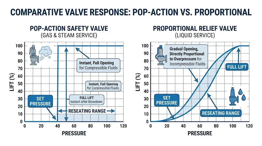
In common process-industry terminology, a rapid-opening safety valve and a proportional-opening liquid relief valve perform different functions during the early stages of lift. A compressible fluid expands as pressure falls through the nozzle and can generate the additional flow forces used to produce pop action. A liquid generally requires a more progressive response, although flashing and two-phase services need separate analysis.
The replacement decision can change all of the following:
Opening action: Whether lift develops rapidly or progressively after the set condition is reached.
Required relieving capacity: The flow that must be discharged during the governing overpressure scenario.
Certified capacity: The documented capacity supported for the selected valve, orifice, fluid, pressure, temperature, and configuration.
Blowdown and reseating: The pressure interval between opening and reclosing and the likelihood of stable shutoff after relief.
Back-pressure response: How outlet pressure affects opening force, lift, capacity, and reseating.
Seat tightness: Whether leakage after assembly or repair satisfies the specified acceptance method.
Code acceptance: Whether the replacement still satisfies the construction, certification, inspection, and repair basis of the protected equipment.
Rapid pop action and proportional lift represent different pressure-relief behavior. Final suitability must be confirmed from the actual product design, fluid certification, capacity, and system conditions.
Engineering note: Matching flanges and pressure class establish physical compatibility only. They do not establish functional, capacity, material, installation, or code equivalence.
Composite engineering scenario: A shutdown team installed a warehouse spare on a liquid pump skid because it had the same NPS inlet, outlet, flange class, and set pressure as the removed valve. During commissioning, the replacement opened abruptly, the discharge line vibrated, and the valve repeatedly cycled before developing seat leakage. Review showed that the spare was configured and documented for compressible-fluid service rather than the package’s liquid-relief duty. The correction was to recalculate the blocked-discharge case, select a liquid-certified proportional relief valve, and review the outlet reaction and return-line pressure.
Typical Situations Where Users Try to Substitute
Most substitution requests are created by schedule pressure, unavailable stock, obsolete models, unclear plant terminology, or procurement shortcuts—not by a new relief-system review.
An emergency shutdown requires a replacement before the original model can be delivered.
A buyer finds another valve with the same size, set pressure, and flange class.
The original manufacturer or model is obsolete.
A plant tag calls every device a PSV even though some protect gas and others protect liquid.
A retrofit keeps the original nozzle but changes the medium, throughput, relief scenario, or outlet header.
A maintenance shop wants to use an available spring, disc, or trim from another model.
A process debottleneck increases the required relieving load without changing the connection size.
A new flare or vent-header tie-in changes superimposed or built-up back pressure.
The old datasheet is missing and the replacement is being selected from the nameplate or a photograph.
These situations do not automatically prohibit replacement, but they mean the proposed valve must be treated as an engineering change. The existing nameplate can provide useful identification data, but it does not prove that the original valve was correctly selected for the current process or that the process conditions have remained unchanged.
A defensible replacement review should ask whether the protected equipment, MAWP, set-pressure arrangement, relief scenario, required capacity, fluid phase, temperature, back pressure, inlet piping, outlet piping, materials, and applicable standard remain the same. Any unresolved difference can invalidate the assumption of interchangeability.
Why Safety Valves and Relief Valves Are Not Direct Replacements
Service Medium and Opening Behavior
The first replacement boundary is the relieving fluid and its phase at the valve—not merely the normal process description. Steam, gas, vapor, liquid, flashing liquid, and two-phase flow create different density, compressibility, velocity, force, noise, reaction, and stability conditions as the valve opens.
A safety valve commonly uses disc and huddling-chamber geometry to produce rapid opening in compressible-fluid service. A proportional liquid relief valve generally increases lift as pressure rises above the opening region. Neither behavior should be assumed from the valve name alone. The selected product must have the correct trim, test basis, and documented capacity for the actual medium.
Protected Service
Typical Starting Point
Replacement Risk
Steam
Rapid-opening, steam-certified safety valve under the applicable boiler or pressure-vessel route.
A liquid-only relief valve may lack the required opening action, steam capacity, materials, blowdown control, or code marking.
Gas, Air, or Vapor
Gas-certified safety valve or safety relief valve.
A liquid-only device may not provide verified compressible-flow capacity or stable rapid lift.
Non-Flashing Liquid
Liquid-certified proportional relief valve or suitable safety relief valve.
A gas-oriented pop-action valve may create hydraulic shock, cycling, or unstable lift if not approved for liquid duty.
Flashing Liquid
Case-specific valve and approved flashing or two-phase sizing method.
Treating the service as fully liquid or fully gas can produce an incorrect required area.
The statement “safety valves are for gas and relief valves are for liquid” should therefore be treated as a common API and process-industry starting point, not a universal definition. ISO 4126-1 applies to safety-valve products irrespective of fluid. The actual product documentation and application standard must decide whether a specific valve is suitable.
Composite engineering scenario: A general process relief valve was proposed as a replacement for a boiler safety valve because the connection dimensions and set pressure matched. Engineering rejected the substitution because the replacement did not carry the required boiler safety-valve certification or documented steam capacity and did not have the approved blowdown and lifting-device arrangement. The issue was not physical fit; it was the absence of evidence that the valve could perform and be accepted under the boiler code route.
Capacity, Blowdown, and Reseating Can Change
A replacement with the same set pressure can still provide a different effective orifice, certified capacity, opening curve, blowdown, and reseating pressure. Set pressure confirms when the specified opening response begins under the applicable test procedure. It does not prove how much fluid the valve can pass or whether the valve will remain stable in service.
Set pressure affects when protective opening begins.
Overpressure is the pressure increase above set pressure while the valve is relieving.
Accumulation is the pressure increase above the protected equipment’s MAWP or other allowable pressure boundary during the event.
Required relieving capacity is the flow demand determined from the governing relief scenario.
Certified or project-accepted capacity is the documented flow performance of the selected valve and configuration.
Effective orifice area influences the rated flow capacity and cannot be inferred from the inlet flange alone.
Blowdown affects the pressure interval between opening and reseating.
Seat tightness affects normal-service leakage but does not prove adequate relieving capacity.
Required relieving capacity must be compared with the documented capacity of the proposed replacement. A valve that opens but cannot pass the required load may allow the protected pressure to continue rising beyond the permitted accumulation. Conversely, an unnecessarily large orifice can contribute to chatter if the actual relief load cannot sustain stable lift.
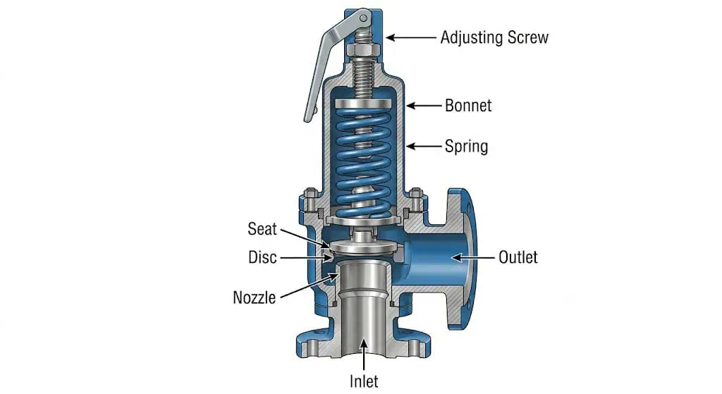
Similar external bodies can contain different nozzles, discs, effective orifices, springs, guides, seats, and blowdown arrangements. These differences can change capacity and replacement suitability.
Composite engineering scenario: A process unit was debottlenecked, increasing the maximum blocked-outlet flow. During the next turnaround, procurement ordered a dimensionally identical replacement based on the old nameplate. The new valve had the correct set pressure but a smaller documented effective orifice than the original configuration and could not satisfy the revised required relieving load. The correction was to repeat the sizing review and select a larger certified orifice rather than approve the same connection size as proof of equivalence.
Reseating behavior also matters. A replacement with different internal geometry or blowdown settings may remain open longer, close too early, cycle around the set point, or leak after operation. Operating pressure close to set pressure, variable back pressure, dirty media, and damaged seating surfaces can amplify these differences.
Back Pressure and Piping Effects Do Not Disappear During Replacement
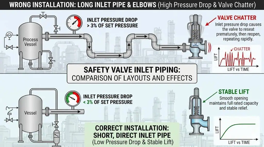
Replacement review must include the complete installed inlet and outlet system because bench test results do not reproduce all field pressure losses and piping forces. A correct set-pressure test confirms the valve’s adjustment under defined conditions. It does not prove that the installed inlet branch is non-restrictive, that the discharge header pressure is acceptable, or that the piping is correctly supported.
A restrictive inlet can cause pressure at the valve nozzle to fall after lift, even while the protected vessel remains above the required pressure. The valve may then close, pressure rebuilds, and the opening cycle repeats. This is a common mechanism behind chatter.
Outlet pressure can be divided into:
Superimposed back pressure: Pressure present at the valve outlet before it opens.
Built-up back pressure: Pressure generated by relieving flow through the valve outlet, discharge piping, silencer, common header, vent, or flare system.
Back pressure can influence opening force, lift, effective capacity, blowdown, and reseating. Conventional spring-loaded, balanced bellows, and pilot-operated designs do not have identical back-pressure behavior. Replacing a balanced valve with a conventional valve, or changing the pilot arrangement, requires manufacturer-supported performance data and a current outlet-system calculation.
A replacement valve can pass workshop testing and still chatter when the installed inlet creates excessive relieving-flow pressure loss or the outlet creates unacceptable back pressure.
Composite engineering scenario: A conventional replacement valve passed set-pressure and seat-tightness tests but chattered after a plant connected additional relief devices to the same flare header. The replacement valve was blamed initially. Review showed that the modified header generated higher built-up back pressure during simultaneous relief. The corrective action was to recalculate the flare-header condition, review the valve’s back-pressure envelope, and select a suitable balanced or pilot-operated configuration rather than repeatedly adjust the spring.
Any substitution should be treated as a new valve-selection review unless documented interchangeability already exists for the exact models, internals, certification, and service. The following checks establish whether the replacement provides functional equivalence rather than dimensional similarity.
Check Item
Why It Matters
Minimum Evidence
Protected equipment
Defines the pressure boundary that must remain protected.
Equipment datasheet, MAWP, design temperature, and code route.
Governing relief scenario
Determines the required relieving load.
Approved blocked-outlet, fire, tube-rupture, gas-blowby, thermal-expansion, pump, or other relief calculation.
Fluid composition and phase
Controls sizing method, opening behavior, materials, and capacity basis.
Relieving-condition composition, phase, density, molecular weight, viscosity, or two-phase data as applicable.
Operating pressure and set pressure
Determine operating margin and when protective opening begins.
Operating envelope, MAWP or allowable limit, set-pressure basis, and manufacturer data.
Overpressure and accumulation
Define the permitted temporary pressure rise during the event.
Applicable code provision and approved relief basis.
Required relieving capacity
Defines the flow that must be discharged.
Approved engineering calculation.
Certified or accepted capacity
Confirms that the selected valve and orifice satisfy the required load.
Certified capacity data, manufacturer sizing report, or project-approved performance basis.
Opening characteristic
Determines whether rapid or proportional lift is appropriate.
Product datasheet, fluid certification, test standard, and manufacturer statement.
Blowdown and reseating
Affect process recovery, cycling, product loss, and seat condition.
Manufacturer data and applicable test or adjustment requirement.
Superimposed and built-up back pressure
Can alter lift, effective capacity, blowdown, and reseating.
Outlet-system calculation and valve performance envelope.
Inlet pressure loss
Can cause unstable opening and chatter.
Relieving-flow calculation or approved engineering analysis.
Materials
Control corrosion, erosion, galling, sealing, and temperature capability.
Affect alignment, drainage, reaction loads, and safe discharge.
Approved installation drawing and manufacturer instructions.
Code and certification
Determine legal, owner, and inspection acceptance.
Exact code, edition, nameplate marking, certificates, and inspection plan.
Repair route
Controls adjustment, component replacement, testing, documentation, and resealing.
Approved repair procedure and authorization where required.
A replacement decision starts with the protected equipment and governing relief scenario, then proceeds through fluid, capacity, valve behavior, piping, materials, testing, and code acceptance.
A replacement should not be approved while required capacity, relieving phase, outlet back pressure, or certification remains unknown. Missing information may allow a preliminary quotation, but it does not allow a defensible final selection.
Procurement and maintenance teams do not need to perform the full relief calculation, but they must prevent technical data from being reduced to size, set pressure, and price.
Before issuing a purchase order or installing the replacement, confirm:
The submitted datasheet identifies the same protected equipment and relief scenario.
The medium, composition, phase, operating temperature, and relieving temperature are correct.
The set pressure and applicable equipment limit are clearly separated.
The required relieving capacity is stated with units and calculation basis.
The offered valve’s certified or accepted capacity meets the required load.
The selected orifice is identified; it is not inferred from the inlet connection.
The valve type and opening characteristic are suitable for the fluid.
Superimposed and built-up back pressure have been declared.
The inlet and outlet piping remain within the accepted installation basis.
Body, nozzle, disc, guide, spring, bellows, gaskets, and seat materials are specified.
Metal-seat or soft-seat requirements and leakage acceptance are stated.
The applicable code, standard, edition, nameplate marking, and certification route are identified.
Set-pressure and seat-tightness test records will be supplied.
Material certificates, inspection records, and capacity documents are included where required.
The valve can be safely installed, removed, tested, and maintained.
Any field adjustment, component substitution, or repair has an approved procedure.
The adjustment is locked, sealed, documented, and traceable after calibration.
Procurement warning: The most common replacement shortcut is buying by connection size, pressure class, and set pressure only. Those three fields do not prove relieving capacity, fluid suitability, back-pressure performance, or code equivalence.
A controlled safety valve datasheet for RFQ should be used whenever the original model is obsolete, process conditions have changed, or a different valve family is proposed.
Maintenance teams should also compare the old valve’s failure history with the new selection. Repeated seat leakage, set-pressure drift, chatter, guide sticking, corrosion, or bellows damage may indicate a system problem that will not be corrected by installing another valve of the same nominal size.
Common Problems After the Wrong Replacement
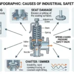
Chatter, Cycling, and Seat Damage
Chatter is repeated high-amplitude contact between the disc and seat, while flutter generally describes lower-amplitude rapid movement. Both indicate unstable interaction between the valve and the pressure system. A replacement can contribute to instability when its opening characteristic, orifice, blowdown, inlet requirements, or back-pressure limits do not match the duty.
Typical causes include:
A rapid-opening valve used in unsuitable liquid service.
An oversized orifice that cannot maintain stable lift at the actual flow.
Excessive inlet pressure loss after the valve starts relieving.
Variable or excessive outlet back pressure.
Incorrect blowdown adjustment.
Two-phase, flashing, pulsating, or acoustically unstable flow.
Guide friction, deposits, corrosion, misalignment, or spring problems.
Heavy unsupported outlet piping applying load to the valve body.
Chatter can damage the nozzle, disc, guide, spindle, spring assembly, bellows, piping, and equipment nozzle in a short period. Increasing spring compression or repeatedly lapping the seat does not correct an inlet-loss, oversizing, or back-pressure problem.
Observed Symptom
Possible Replacement Error
Correct Review
Rapid repeated opening
Wrong opening characteristic, oversized orifice, or restrictive inlet.
Check fluid duty, required capacity, selected orifice, and inlet loss.
Valve vibrates during discharge
Unstable lift, outlet back pressure, poor support, or two-phase flow.
Review valve dynamics, outlet hydraulics, support, and phase behavior.
Seat damaged after few lifts
Chatter, debris, hydraulic shock, or incorrect blowdown.
Inspect internals and correct the system cause before repair.
Valve fails to reach stable lift
Insufficient flow, wrong trim, inlet pressure collapse, or high back pressure.
Revalidate the relief load and complete system installation.
Poor Reseating and Nuisance Leakage
Leakage after relief is often blamed on the seat, but the root cause may be the replacement valve’s operating margin, blowdown, outlet pressure, materials, or installation. The valve may have passed a seat-tightness test before installation and still leak after a real event because the installed conditions damage or contaminate the seating surfaces.
Common causes include:
Normal operating pressure remains too close to set pressure.
Pressure pulsation causes repeated simmer or micro-lift.
Blowdown or closing behavior does not suit the process.
Variable back pressure prevents stable reseating.
Debris is carried into the nozzle and seat during lift.
The disc, guide, or spindle is misaligned.
Pipe strain or non-approved mounting orientation creates side load.
Nozzle and disc materials are unsuitable for corrosion or erosion.
A soft seat is incompatible with temperature or fluid chemistry.
Repair adjustment was not verified or resealed correctly.
Seat tightness testing and capacity verification should not be confused. API 527 or another approved method can establish leakage acceptance for applicable valves, but it does not prove that the valve has enough capacity or that the outlet system is acceptable. See the API 527 seat-tightness guide.
Composite engineering scenario: A replacement valve began leaking several weeks after installation in chloride-bearing condensate service. The new valve had a corrosion-resistant body, but the nozzle, disc, and guide materials had been copied from a general-service trim. Localized corrosion damaged the seat and increased guide friction. The corrective action was to specify the complete wetted and guiding-component materials rather than treating body material as proof of compatibility.
A replacement can appear to operate correctly and still be rejected because its certification, capacity evidence, marking, testing, or repair history does not match the protected equipment.
Typical nonconformities include:
Using a general process relief valve in a boiler position requiring an applicable boiler safety-valve route.
Using a valve with no documented capacity for the specified steam, gas, or liquid service.
Installing a model with the correct set pressure but the wrong effective orifice.
Accepting “ASME compliant” without confirming the required code marking or certification scope.
Using the wrong standard edition or an unsupported material substitution.
Changing a spring, nozzle, disc, or adjusting ring without manufacturer-approved interchangeability.
Performing repair or adjustment without the required quality-system controls.
Failing to perform or document set-pressure and seat-tightness tests after repair.
Returning the valve to service without locking or sealing the adjustment.
Installing the valve differently from the arrangement used for approval.
Document or Evidence
What It Proves
What It Does Not Prove
Nameplate and model details
Valve identity, size, set pressure, and applicable markings.
That the current relief scenario and required capacity were correctly calculated.
Set-pressure test
The adjusted opening condition under the specified test procedure.
Certified capacity or installed-system stability.
Seat-tightness test
Leakage performance at the specified test condition.
Required capacity, inlet-loss acceptability, or back-pressure suitability.
Certified capacity data
Documented flow performance for a defined configuration and fluid basis.
That the proposed process scenario is correct.
Material certificates
Traceability of the specified pressure-containing or internal components.
Compatibility unless the actual medium and temperature were evaluated.
Repair report and seal record
What was repaired, adjusted, tested, and secured.
That the original system-selection problem has been corrected.
Where the owner, jurisdiction, or NBIC route requires recognized pressure-relief-valve repair authorization, the repair organization’s National Board VR scope should be confirmed before the valve is returned to service.
When a Replacement May Be Considered
Conditions That Must Be True Before Engineers Approve It
A replacement may be approved when engineering review demonstrates that the proposed valve provides an acceptable pressure-protection function for the actual duty. This does not mean safety valves and relief valves are generally interchangeable. It means the specific proposed model, configuration, and installation have been revalidated.
At minimum, all of the following should be true:
The protected equipment and applicable pressure boundary are clearly identified.
The governing relief scenario has been confirmed or recalculated.
The relieving fluid, composition, phase, and temperature are known.
The proposed valve is designed and documented for the actual fluid duty.
The set pressure satisfies the applicable code and equipment limit.
The allowable overpressure or accumulation basis remains valid.
The required relieving capacity has been recalculated or confirmed.
The proposed valve’s certified or project-accepted capacity meets or exceeds the required load.
The selected effective orifice is suitable and is not unnecessarily oversized.
The opening characteristic is appropriate for the service.
Operating margin, blowdown, and reseating behavior are acceptable.
Superimposed and built-up back pressure are within the supported performance envelope.
Inlet pressure loss and outlet resistance have been checked at relieving flow.
Body, nozzle, disc, guide, spindle, spring, bellows, gasket, and seat materials are compatible.
The pressure-temperature rating is suitable at relieving conditions.
The mounting orientation, support, drainage, venting, and discharge location are acceptable.
The applicable construction code, product standard, nameplate, and certification requirements are satisfied.
The required set-pressure, seat-tightness, material, inspection, and capacity documents will be supplied.
The maintenance and repair route is available for the new design.
The substitution has been documented and approved through the project’s management-of-change or equivalent process.
Practical conclusion: A replacement is justified by demonstrated engineering equivalence and documented acceptance—not by visual similarity, warehouse availability, or the fact that the flanges align.
Relevant standards and their roles should also be separated correctly:
Authorization and VR stamp for pressure relief valve repair.
Relevant where the owner, jurisdiction, or applicable NBIC route requires authorized repair.
The purchased standard edition, local regulations, protected-equipment code, manufacturer data, and owner requirements remain controlling. The replacement file should identify the exact basis rather than state only “ASME,” “API,” or “ISO compliant.”
So, can a safety valve replace a relief valve, or can a relief valve replace a safety valve? Not as an automatic one-for-one substitution. A specific replacement can be considered only after the complete pressure-protection duty has been verified and the proposed valve has demonstrated suitable opening behavior, capacity, pressure limits, back-pressure performance, materials, installation, testing, certification, and maintainability.
In practical plant work, most incorrect substitutions occur because teams compare hardware before they compare the relief function. That sequence should be reversed: define the protected equipment and governing scenario first, then select and document the valve.
FAQ
Can a safety valve replace a relief valve?
Not automatically. A specific safety valve may replace a relief valve only when it is designed, sized, certified, and approved for the actual liquid or other service. A gas- or steam-oriented pop-action valve should not be accepted for liquid duty merely because its connections and set pressure match.
Can a relief valve replace a safety valve?
Not automatically. A liquid-only proportional relief valve may not provide the required rapid opening, compressible-fluid capacity, blowdown behavior, or code certification for steam, gas, air, or vapor service. The complete duty must be revalidated.
What should be checked before replacing one with the other?
Check the protected equipment, governing relief scenario, fluid and phase, set pressure, overpressure or accumulation basis, required capacity, certified capacity, opening characteristic, blowdown, back pressure, piping, materials, temperature, code route, testing, and maintenance requirements. The replacement should be processed as an engineering change, not as a dimensional spare-parts substitution.
Why do wrong substitutions often leak after installation?
Because tight reseating depends on more than the bench set pressure. Unsuitable opening behavior, inadequate operating margin, incorrect blowdown, back pressure, inlet pressure loss, contamination, pipe strain, corrosion, seat materials, and poor repair control can all cause post-installation leakage.
Does the same connection size mean the valves have the same capacity?
No. Connection size confirms the physical piping interface. Valves with the same inlet and outlet sizes can have different effective orifices, coefficients, lifts, certified capacities, fluid approvals, and application limits.
Why is certified relieving capacity more important than connection size?
Certified or project-accepted capacity shows whether the selected valve can pass the required relief load under defined conditions. A valve that physically fits but cannot discharge the governing load does not adequately protect the equipment.
Can a safety valve be used in liquid service?
Yes, when the specific valve design and certification support liquid service. The term safety valve is used more broadly in some standards and manufacturer product families. The actual liquid capacity, opening characteristic, stability, and application data must be checked.
How does back pressure affect replacement suitability?
Back pressure can affect opening force, lift, effective capacity, blowdown, and reseating. A replacement with a different conventional, balanced bellows, or pilot-operated configuration may have different allowable back-pressure limits. The complete outlet system must be reviewed.
Does passing a set-pressure test prove the replacement is suitable?
No. A set-pressure test verifies the adjusted opening condition under the specified test procedure. It does not prove sufficient relieving capacity, acceptable inlet pressure loss, allowable outlet back pressure, correct materials, or stable field performance.
What standards matter when reviewing a replacement?
The relevant standards depend on the protected equipment and service. Common directions include ASME BPVC Section I for power boilers, Section VIII for pressure vessels, API 520 Part I for sizing and selection, API 520 Part II for installation, API 521 for relief systems, API 526 for standardized flanged PRVs, API 527 for seat tightness, API RP 576 for inspection, ISO 4126 for product requirements, and National Board or NBIC requirements for applicable repair routes.
When is a pilot-operated replacement worth considering?
A pilot-operated valve may be considered when tight shutoff, a high operating-pressure ratio, large capacity, or specific back-pressure behavior provides a real benefit. The service must also be suitable for the pilot circuit. Dirt, wax, polymer, liquid carryover, freezing, blocked sensing passages, and limited maintenance capability can make a pilot-operated replacement less reliable.
Related Engineering Guides
Continue with these focused guides when the engineering review reaches the corresponding sizing, selection, installation, or maintenance question:
To provide the best experiences, we use technologies like cookies to store and/or access device information. Consenting to these technologies will allow us to process data such as browsing behavior or unique IDs on this site. Not consenting or withdrawing consent, may adversely affect certain features and functions.
Functional
Always active
The technical storage or access is strictly necessary for the legitimate purpose of enabling the use of a specific service explicitly requested by the subscriber or user, or for the sole purpose of carrying out the transmission of a communication over an electronic communications network.
Preferences
The technical storage or access is necessary for the legitimate purpose of storing preferences that are not requested by the subscriber or user.
Statistics
The technical storage or access that is used exclusively for statistical purposes.The technical storage or access that is used exclusively for anonymous statistical purposes. Without a subpoena, voluntary compliance on the part of your Internet Service Provider, or additional records from a third party, information stored or retrieved for this purpose alone cannot usually be used to identify you.
Marketing
The technical storage or access is required to create user profiles to send advertising, or to track the user on a website or across several websites for similar marketing purposes.