A lever-loaded safety valve uses a weight acting through a lever arm to hold the disc on the seat. System pressure produces an upward force beneath the disc. When the pressure force and resulting moment overcome the closing load created by the weight and lever geometry, the disc lifts and the valve discharges. This traditional …

A lever-loaded safety valve uses a weight acting through a lever arm to hold the disc on the seat. System pressure produces an upward force beneath the disc. When the pressure force and resulting moment overcome the closing load created by the weight and lever geometry, the disc lifts and the valve discharges.
This traditional design is also called a weight-and-lever safety valve or weighted safety valve. It must not be confused with a modern spring-loaded safety valve fitted with a lifting, easing or try lever. In the modern design, the spring supplies the normal closing force; the lever is only an auxiliary manual lifting device.
Engineering takeaway: The operating principle is a moment balance, but reliable protection depends on more than weight position. Disc area, lever ratio, pivot friction, seat condition, linkage wear, required relieving capacity, outlet condition, tamper control and the applicable legacy-equipment rules must all be reviewed.
First Clarify What “Lever Safety Valve” Means
| Term Used in an RFQ | Actual Construction | What the Lever Does | Recommended Wording |
|---|---|---|---|
| Lever-loaded safety valve | Weight-and-lever direct-loaded valve | Provides the main closing load | “Lever-loaded / weight-and-lever safety valve” |
| Safety valve with lifting lever | Usually spring-loaded | Allows controlled manual lifting where permitted | “Spring-loaded safety valve with lifting lever” |
| Packed lever safety valve | Spring-loaded valve with sealed manual lifting mechanism | Allows manual lift while reducing leakage through the cap | State spring-loaded construction and packed lever option |
| Try lever / easing lever | Accessory on a modern safety valve | Checks that moving parts can be lifted under approved conditions | State the actual valve type plus try/easing lever |
Procurement warning: Do not write only “lever safety valve.” ZOBAI’s current product page uses that phrase mainly for modern safety valves fitted with lifting or try levers, while this article addresses the older lever-loaded mechanism.
For modern lifting-lever products, see Safety Valves with Lifting, Try or Packed Levers. For the spring-loaded operating principle, see How a Spring-Loaded Safety Valve Works.
60-Second Working Sequence
| Stage | What Happens | Main Risk |
|---|---|---|
| Closed | The weight produces a closing moment through the lever and linkage. | Seat leakage, weight movement or linkage friction. |
| Pressure rises | Upward force increases beneath the disc. | Sticking can delay the real opening point. |
| Moment balance is reached | The opening moment becomes equal to or greater than the closing moment. | Weight position or pivot wear can change the effective setting. |
| Disc lifts | The valve creates a flow path through the seat and outlet. | Opening alone does not prove adequate capacity. |
| Pressure is relieved | Steam, air or gas leaves the protected equipment. | Outlet obstruction or insufficient flow area. |
| Pressure falls and valve reseats | The lever-weight load returns the disc to the seat. | Seat damage, vibration or linkage friction can prevent tight closure. |
What Is a Lever-Loaded Safety Valve?
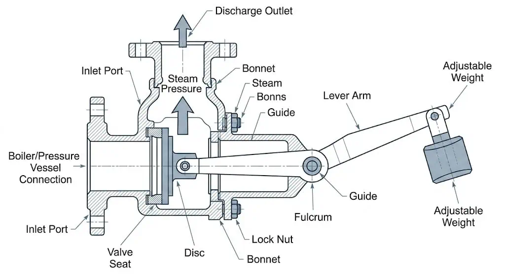
A lever-loaded safety valve is a direct-loaded pressure-relief device in which a weight and lever mechanism oppose the opening force produced by pressure beneath the disc. The weight does not usually act directly above the seat. Its load is transmitted through a lever, fulcrum, link and spindle or disc mechanism.
This design appears mainly in:
- older steam-boiler installations;
- legacy marine or stationary equipment;
- historical boiler drawings and textbooks;
- training rigs used to demonstrate force balance;
- replacement evaluations where original records are incomplete.
The design is mechanically visible, but that does not make its operating pressure or capacity self-evident. A complete review still requires the protected equipment, MAWP or approved pressure basis, set pressure, required capacity, valve flow area, discharge system and applicable jurisdiction.
Standards terminology: A lever-and-weight valve belongs to the broader family of direct-loaded safety valves. A spring-loaded safety valve is also direct-loaded, but uses a spring instead of an external weight-and-lever mechanism.
Main Parts and Their Functions
| Part | Function | What to Inspect |
|---|---|---|
| Valve body | Contains pressure and forms the internal flow path. | Pressure rating, cracking, corrosion, erosion and nozzle connection. |
| Nozzle / seat | Provides the inlet throat and sealing edge. | Wire drawing, scale, corrosion, deposits and seat damage. |
| Disc / plug | Closes the seat and lifts to admit relieving flow. | Alignment, deposits, wear, sticking and surface damage. |
| Lever arm | Converts the weight force into a moment at the valve mechanism. | Bending, unauthorized modification, interference and geometry. |
| Weight | Provides the adjustable gravitational load. | Correct mass, marked position, locking, seal and evidence of movement. |
| Fulcrum / pivot | Provides the lever rotation point. | Wear, corrosion, looseness, binding and lubrication condition where applicable. |
| Link / spindle | Transfers lever force to the disc. | Misalignment, mechanical play, distortion and friction. |
| Stops and locking features | Limit movement and prevent unauthorized weight relocation. | Missing stops, broken seals and improvised fasteners. |
| Outlet | Routes relieved fluid to a safe location. | Obstruction, condensate, drainage, piping load and personnel exposure. |
Working Principle: Force and Moment Balance
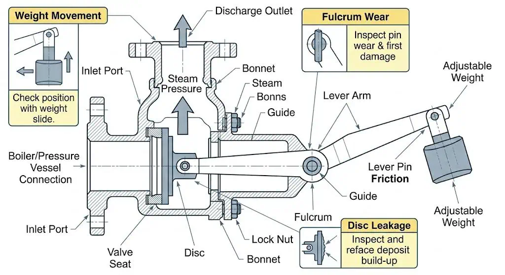
The basic opening force is produced by inlet pressure acting over the effective disc area:
Opening force: Fp ≈ P × Aeffective
The opening force acts through the valve linkage at an effective distance from the pivot. The weight produces an opposing moment:
Opening moment: Mopen ≈ Fp × Lvalve
Closing moment: Mclose ≈ W × Lweight
Where:
- P is inlet pressure;
- Aeffective is the effective pressure area beneath the disc;
- Lvalve is the effective moment arm from the valve linkage to the pivot;
- W is the gravitational force of the weight;
- Lweight is the distance between the weight and pivot.
In a simplified friction-free model, opening begins when the opening moment equals or exceeds the closing moment. Real operation also includes disc weight, linkage geometry, friction, seat adhesion, flow reaction, vibration and manufacturing tolerances.
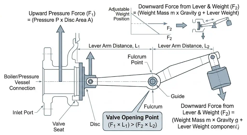
Equation boundary: These simplified equations explain the mechanism. They do not establish a legal set pressure, certified capacity or an acceptable field-adjustment method.
The Six-Stage Operating Cycle
-
The valve remains closed.
The lever-weight closing moment keeps the disc on the seat while the protected-system pressure remains below the opening condition. -
Pressure force increases.
As inlet pressure rises, upward force beneath the disc increases. Any seat adhesion or linkage friction can delay motion. -
The mechanism reaches the opening balance.
The effective opening moment equals or exceeds the closing moment. The actual response depends on geometry, friction and valve condition. -
The disc lifts.
A flow path forms between the disc and seat. The lift may remain limited by the design and linkage travel. -
The valve discharges.
The valve must pass enough flow to control the credible overpressure scenario. Outlet restriction can affect performance and safety. -
The valve reseats.
After pressure falls, the closing moment returns the disc to the seat. Contamination, wear or vibration may prevent tight closure.
Opening is not the same as protecting the equipment. A valve may lift mechanically yet lack the required flow capacity or documentation for the current boiler, vessel or operating duty.
Why the Weight Position Changes Opening Pressure
Moving the weight farther from the fulcrum increases the closing moment when the mass remains the same. Moving it closer reduces the closing moment. This makes an exposed weight a major tamper and maintenance risk.
Weight Moved Outward
Closing moment generally increases. The valve may open at a higher pressure than intended.
Weight Moved Inward
Closing moment generally decreases. The valve may open early or discharge during normal fluctuation.
The weight position should be identified, secured and connected to a controlled test record. Paint marks alone are weak evidence because they can be recreated after an unauthorized change.
Do not move the weight to stop leakage. Leakage can result from seat damage, scale, operating pressure, distortion or outlet vibration. Increasing closing load can hide the symptom while raising the real opening pressure.
How Friction, Wear and Sticking Change Real Operation
The simple moment equation assumes free movement. Legacy equipment rarely behaves as an ideal frictionless mechanism.
| Condition | Effect on the Mechanism | Possible Result |
|---|---|---|
| Corroded pivot | Adds resistance to initial movement. | Late or irregular opening. |
| Worn pin or oval hole | Changes effective geometry and creates lost motion. | Uncertain opening point and unstable reseating. |
| Scale at the seat | Creates adhesion or blocks free disc movement. | Sticking, leakage or delayed opening. |
| Bent lever | Changes moment arms and alignment. | Changed load transfer and mechanical interference. |
| Loose linkage | Introduces backlash before the disc responds. | Inconsistent lift and impact. |
| Outlet vibration | Applies cyclic force to the valve body and mechanism. | Seat damage, weight movement or poor reseating. |
A visual check that confirms “the lever moves” is not equivalent to set-pressure verification, relieving-capacity confirmation or a controlled return-to-service test.
Mechanical Opening vs Required Relieving Capacity
The lever mechanism establishes a closing load. It does not by itself establish the valve’s flow capacity.
Capacity depends on:
- nozzle and minimum flow area;
- disc lift and curtain area;
- steam, air, gas or other medium;
- set and relieving pressure;
- relieving temperature;
- discharge coefficient or approved performance data;
- outlet pressure and discharge arrangement.
Set-Pressure Question
At what pressure does the valve demonstrate its approved opening response?
Capacity Question
Can the valve pass at least the required relief load under the approved conditions?
When original capacity records are missing, do not infer capacity from connection size, lever length or external appearance. Use the Safety Valve Sizing and Certified Capacity Guide for the modern review sequence.
Lever-Loaded vs Spring-Loaded Safety Valves
| Selection Factor | Lever-Loaded / Weighted Valve | Modern Spring-Loaded Valve |
|---|---|---|
| Main closing load | External weight acting through a lever | Compressed spring acting through the spindle and disc assembly |
| Adjustment method | Weight mass and position, plus lever geometry | Controlled spring compression and valve-specific adjustment |
| Tamper exposure | High when the weight is externally accessible | Usually controlled by cap, seal, tag and calibration record |
| Friction points | External pivot, pin, link and internal seat/disc | Guide, spindle, spring washers, disc and seat |
| Capacity documentation | Often incomplete on old equipment | More commonly supported by current manufacturer data and certification |
| Typical project context | Legacy boiler, marine rule, historical or training equipment | Modern boiler, vessel, process and utility applications |
| Replacement approach | Legacy-equipment engineering review | Select from the current relief basis and applicable product route |
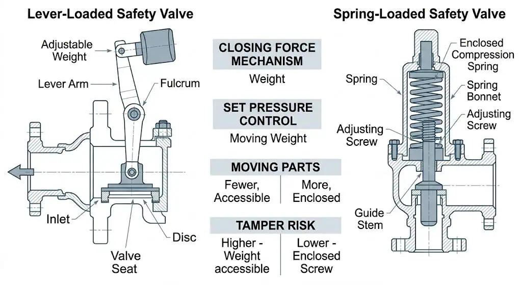
For current spring-loaded products, see Spring-Loaded Safety Valves. For design selection, use the Safety Valve Selection Guide.
What a Lifting Lever Does—and Does Not Prove
A lifting, easing or try lever is an accessory on many spring-loaded safety valves. It mechanically lifts the disc when used under approved conditions. It does not provide the normal closing load.
| A Lifting Lever May Help Confirm | A Lifting Lever Does Not Prove |
|---|---|
| The mechanism can be manually moved under the specified test condition. | The valve opens at the correct set pressure. |
| The disc is not completely seized at the time of the check. | The valve has sufficient certified relieving capacity. |
| The external lever and linkage operate. | The seat meets the specified leakage acceptance. |
| A required service or inspection function is available. | The inlet and outlet piping are correctly designed. |
Manual-lift safety: Do not operate a lifting lever casually. The procedure must consider minimum pressure, hot or hazardous discharge, downstream routing, personnel exposure and the manufacturer’s instructions.
Where Lever-Loaded Valves May Still Be Found
Lever-loaded or weighted safety valves may remain on older steam boilers, marine boilers and other legacy equipment. The engineering question is not simply whether the mechanism still moves; it is whether continued use is allowed and whether the valve still provides verifiable protection.
Review:
- the current jurisdiction and equipment code;
- whether existing service, repair or replacement is permitted;
- the protected equipment’s current MAWP and capacity;
- changes to burners, steam generation, pressure or process duty;
- original valve capacity and test records;
- availability of qualified repair procedures and parts;
- outlet routing, drainage and personnel exposure.
Specific U.S. marine example: Current 46 CFR 52.01-120 states that lever or weighted safety valves already installed may continue in use and may be repaired, but when repairs are not possible they must be replaced by valves conforming to that section. This is a marine-boiler rule and should not be generalized to other jurisdictions.
Engineering Risks and Common Failure Modes
| Failure Mode | Likely Cause | Potential Consequence | Required Review |
|---|---|---|---|
| Weight movement | Unauthorized adjustment, vibration or missing lock | Unknown opening pressure | Weight identification, position, seal and controlled test |
| Seat leakage | Scale, corrosion, damage or pressure too close to opening condition | Steam loss, erosion and unsafe informal adjustment | Seat inspection, pressure trend and approved repair |
| Late opening | Pivot friction, seat adhesion, bent linkage or excess closing moment | Equipment pressure exceeds intended limit | Mechanism inspection and calibrated functional test |
| Insufficient relief | Small flow area, restricted lift, blocked outlet or changed boiler duty | Pressure continues rising after opening | Required load and documented valve capacity |
| Poor reseating | Seat damage, loose pin, vibration, deposits or outlet force | Continuous leakage and further damage | Seat, linkage, outlet and pressure-decay review |
| Broken traceability | Informal repair, unmarked weight or missing records | Cannot prove setting, capacity or authorization | Repair dossier, nameplate, test report and jurisdiction |
Illustrative Legacy-Equipment Cases
Fictional training example — not field data
Case 1: Leakage “Fixed” by Moving the Weight
An operator moved the weight outward after noticing steam leakage. Leakage reduced, but the real opening pressure became unknown. Inspection later found a damaged seat and operating-pressure fluctuation.
Correct response: restore controlled configuration, inspect the seat and linkage, verify the equipment pressure basis and perform an authorized test. Do not use weight position as a leakage-control adjustment.
Fictional training example — not field data
Case 2: Buyer Ordered the Wrong “Lever Valve”
A buyer intended to purchase a modern spring-loaded steam valve with a lifting lever but wrote only “lever safety valve.” The supplier interpreted the request as a lever-loaded legacy design.
Correct response: revise the RFQ to state the full construction, required lifting-lever type, set pressure, capacity, steam condition, connections and documentation.
Fictional training example — not field data
Case 3: Same Connections, Unknown Protection
A visually similar replacement matched the inlet and outlet sizes of an old weighted valve. The original flow area and required boiler capacity were not available.
Correct response: hold the purchase until the protected equipment, pressure basis, required capacity and current code route are established.
Inspection and Engineering Review Workflow
-
Identify the actual valve type.
Confirm lever-loaded construction versus a spring-loaded valve with lifting lever. -
Record the existing configuration.
Photograph the nameplate, weight, marked position, lever, pivot, linkage, inlet and outlet. -
Confirm the protected equipment basis.
Identify the equipment, MAWP or design pressure, current duty and jurisdiction. -
Inspect the pressure boundary and seating parts.
Check body, nozzle, disc and seat for corrosion, cracking, erosion and deposits. -
Inspect the external mechanism.
Check the lever, weight, fulcrum, pins, links, stops, locking and evidence of adjustment. -
Review the relief load and capacity.
Do not infer capacity from connection size. Establish the required current duty. -
Review the outlet and installation.
Check obstruction, drainage, reaction, piping load and safe discharge. -
Determine the authorized test or repair route.
Use the applicable jurisdiction, owner procedure and qualified repair organization. -
Make a repair-versus-replacement decision.
Consider capacity evidence, condition, parts, documentation and future maintenance.
Use the Safety Valve Maintenance and Inspection Guide for broader plant inspection planning.
When Repair May Be Reasonable—and When Replacement Is Safer
| Review Condition | Repair May Be Considered When | Replacement Is Usually Stronger When |
|---|---|---|
| Jurisdiction | Continued use and repair are expressly permitted. | Renewal rules require a current conforming design. |
| Capacity | The current required load and valve capacity remain verifiable. | Original capacity evidence is missing or current duty has changed. |
| Mechanism | Lever, pivot and linkage can be restored to controlled geometry. | Parts are worn, improvised, cracked or unavailable. |
| Seat and body | Pressure boundary and seating surfaces are repairable by an authorized route. | Cracking, severe corrosion or repeated leakage reduces confidence. |
| Traceability | Identification, test basis and repair records can be established. | Nameplate, setting, weight and service history cannot be reconstructed. |
| Lifecycle | The site has trained personnel and controlled inspection procedures. | Future adjustment, tampering and spare-parts risk remain high. |
A replacement does not have to reproduce the old external mechanism. It must reproduce or improve the approved pressure-protection function while meeting the current project and jurisdictional requirements.
Replacement RFQ and Document Checklist
Existing valve photographs and readable nameplate
Lever length, weight mass and marked weight position
Protected equipment type and tag
MAWP / design pressure and temperature
Normal operating pressure and temperature
Required set pressure
Governing relief scenario
Required relieving capacity and units
Steam, air, gas or other medium
Inlet and outlet connections
Outlet destination and any back pressure
Current jurisdiction and code basis
Repair history and last test record
Required material and test certificates
Need for lifting, easing or packed lever on replacement
Installation dimensional constraints
Replacing a Lever-Loaded or Weighted Safety Valve?
Send the existing valve photos, nameplate, protected-equipment data, set pressure, required capacity, medium, connections, outlet arrangement and jurisdictional requirements.
Upload Existing Valve Data Review Modern Spring-Loaded Valves Request a Replacement QuoteStandards and Legal References
The permitted continued use, repair and replacement route depends on the equipment and jurisdiction. The references below have different scopes.
| Reference | Relevant Role | Important Boundary |
|---|---|---|
| 46 CFR 52.01-120 | Current U.S. Coast Guard marine-boiler rule containing a specific provision for existing lever or weighted safety valves | Marine scope only; not a universal industrial rule. eCFR official text |
| ASME BPVC Section XIII | Overpressure-protection and pressure-relief-device rules where the ASME framework applies | Verify the protected equipment section, current edition, marking and certification. ASME official page |
| API 520 Part I | Sizing and selection of modern pressure-relieving devices in covered refinery and process applications | Not a blanket authorization for legacy lever-loaded valves. API official page |
| API 520 Part II | Installation and engineering analysis of modern pressure-relief-device systems | Project-specific inlet and outlet analysis remains required. API official page |
| ISO 4126-1 | General product requirements for safety valves under the ISO route | A product standard, not a complete legacy-equipment replacement decision. ISO official page |
| National Board / NBIC | Inspection, repair and authorization framework where adopted or required | Confirm jurisdiction, repair organization and applicable edition. National Board official page |
| ZOBAI Standards Hub | Navigation to ASME, API, ISO and related procurement guides | Supporting overview only; official standards control. Safety Valve Standards |
Compliance boundary: Do not claim that a repaired or replacement valve is code compliant because it opens or fits the existing piping. Verify the legal manufacturer, capacity, marking, test records, installation and jurisdictional acceptance.
FAQ About Lever-Loaded Safety Valves
What is a lever-loaded safety valve?
It is a direct-loaded safety valve that uses a weight acting through a lever mechanism to apply the main closing load to the disc.
How does a lever-loaded safety valve work?
Pressure beneath the disc creates an opening force and moment. The weight creates an opposing closing moment through the lever. The valve begins to lift when the effective opening moment overcomes the closing moment and mechanical resistance.
Is a lever-loaded valve the same as a safety valve with a lifting lever?
No. In a lever-loaded valve, the weight and lever provide the main closing load. In a spring-loaded valve with a lifting lever, the spring provides the closing load and the lever is only an auxiliary manual lifting device.
Why does moving the weight change the opening pressure?
Moving the weight changes its distance from the fulcrum and therefore changes the closing moment. Moving it outward generally increases closing load; moving it inward generally reduces it.
Can the weight be moved to stop leakage?
No. Moving the weight can change the actual opening pressure. Leakage should be diagnosed through seat, pressure, alignment and mechanism inspection followed by an authorized test.
Are lever-loaded safety valves still allowed?
It depends on the equipment and jurisdiction. Some rules permit continued use or repair of existing valves but require a current conforming replacement when repair is not possible. Confirm the exact applicable rule.
Does a manual lift check prove the set pressure?
No. It may show that the mechanism can move under the check condition, but it does not prove set pressure, certified capacity, leakage acceptance or installation suitability.
Does the connection size prove the relieving capacity?
No. Capacity depends on the flow area, lift, medium, pressure, temperature, discharge coefficient and outlet condition.
When should an old weighted valve be replaced?
Replacement should be strongly considered when capacity evidence, setting, traceability, mechanism condition, qualified repair capability or jurisdictional acceptance cannot be established.
What information is needed for a replacement quote?
Provide valve photos and nameplate, protected equipment, MAWP, set pressure, required capacity, medium, temperature, connections, outlet arrangement, existing dimensions and jurisdictional requirements.
Do Not Replace a Legacy Valve by Appearance Alone
Upload the existing valve, nameplate and protected-equipment data so the replacement can be reviewed against pressure, capacity, installation and legal requirements.
Upload Legacy Valve Data Request a Replacement Review