Share your medium, set pressure, temperature, size, standard, or datasheet, and our team will review your requirement and respond with the appropriate next step.
Difference Between a Safety Valve and a Relief Valve
A safety valve typically develops rapid or pop opening for steam, gas, air, or vapor duty, while a relief valve typically opens progressively for liquid duty. This is the common API and process-industry selection distinction. It is not a universal naming rule: the exact valve design, opening characteristic, fluid certification, certified capacity, and governing equipment code …
A safety valve typically develops rapid or pop opening for steam, gas, air, or vapor duty, while a relief valve typically opens progressively for liquid duty. This is the common API and process-industry selection distinction. It is not a universal naming rule: the exact valve design, opening characteristic, fluid certification, certified capacity, and governing equipment code control the final choice.
ISO 4126-1 uses “safety valve” as a product term irrespective of fluid and identifies itself as a product standard rather than an application standard. Regional practice, manufacturer product families, and plant tags may therefore use the names differently. A safety relief valve may cover steam, gas, vapor, liquid, or more than one fluid category only when the selected design, capacity certification, test basis, materials, and application limits support that duty. PRV and PSV are useful abbreviations, but neither should replace a complete engineering definition on the datasheet.
Both safety valves and relief valves are overpressure-protection devices. Neither should be selected as a normal process-control valve simply because it can open and pass flow. The correct choice must protect the equipment during the governing overpressure scenario, provide sufficient certified or project-accepted relieving capacity, remain stable with the installed inlet and outlet piping, and reseat within an acceptable pressure range.
Users often assume the two valves are interchangeable because their bodies, flange sizes, materials, and pressure classes can look similar.
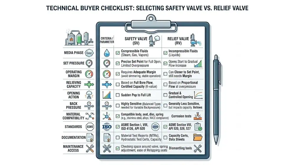
Engineers normally review the medium and phase, opening characteristic, required relieving capacity, set-pressure basis, back pressure, materials, installation, and code route before accepting the valve type.
Incorrect substitution can cause chatter, hydraulic shock, poor reseating, seat leakage, insufficient capacity, unsuitable discharge behavior, or rejection during technical and regulatory review.
Connection size confirms physical fit; it does not prove the valve’s effective orifice, certified capacity, fluid certification, or suitability for the relief scenario.
Expert view: Engineers do not separate safety valves and relief valves by product name alone. They review the protected equipment, governing relief scenario, fluid behavior, opening action, required capacity, back pressure, installation, and applicable certification basis.
Safety valves are commonly associated with rapid opening in compressible-fluid service, while relief valves are commonly associated with proportional opening in liquid service. Final selection still depends on the actual product design, certification, capacity, and system conditions.
What Is a Safety Valve and What Is a Relief Valve
Safety Valve Definition
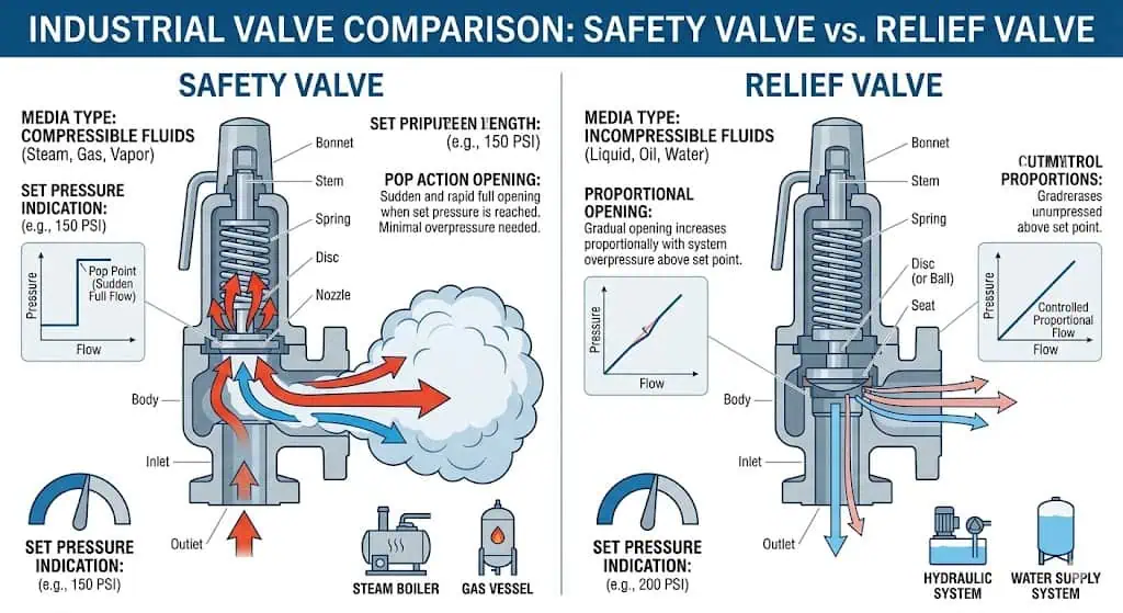
In common process-industry usage, a safety valve is a self-actuated pressure-relieving device characterized by rapid opening and commonly applied to compressible fluids such as steam, gas, air, or vapor. The valve remains closed during normal operation. When inlet pressure reaches the defined set pressure under specified conditions, the disc begins to lift. Flow and pressure forces acting on the disc and huddling-chamber geometry can then produce rapid opening or pop action, allowing the valve to develop a larger relieving area quickly.
The valve must do more than pop open. It must pass the required relieving capacity, remain stable during discharge, limit accumulation within the applicable code boundary, and reseat after pressure falls through the valve’s blowdown range. A valve that opens at the correct set pressure but has insufficient capacity does not provide adequate protection.
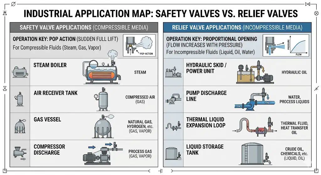
Typical applications include power and process steam systems, boilers, air receivers, gas vessels, compressor systems, vapor spaces, and other pressure equipment containing compressible media. The exact valve type, certification, capacity, and installation requirements depend on the applicable code route and service conditions.
Table: Safety Valve in Practical Use
Item
Practical Meaning
Engineering Check
Typical Media
Steam, air, gas, and vapor.
Confirm the actual fluid composition, phase, relieving temperature, and certification basis.
Opening Characteristic
Rapid opening or pop action is common.
Confirm that the selected model is designed for the required opening behavior.
Main Purpose
Overpressure protection of the protected equipment.
Define the governing relief scenario and required capacity.
Typical Services
Boilers, steam systems, gas vessels, air receivers, and compressor systems.
Confirm ASME, API, ISO, local, or project-specific requirements.
Closing Behavior
Reseats after pressure falls below set pressure through the blowdown range.
Check blowdown, back pressure, seat condition, and process recovery requirements.
In common API and process-industry usage, a relief valve is a self-actuated pressure-relieving device that opens progressively in proportion to increasing pressure and is normally associated with incompressible-liquid service. As inlet pressure rises above the opening region, the valve develops increasing lift and flow area. As pressure falls, the valve reduces lift and eventually reseats.
A relief valve is still an overpressure-protection device. It should not be confused with a pressure-control valve, pressure-reducing valve, bypass regulator, or continuously modulating control valve. Although proportional opening can appear similar to normal pressure control, the relief valve is intended to protect equipment during abnormal pressure conditions.
Typical applications include hydraulic systems, positive-displacement pump discharge, blocked-in liquid sections, thermal expansion relief, liquid process equipment, and storage or transfer systems. The required capacity may be small for thermal expansion or much larger for pump or process-failure scenarios. The valve must therefore be sized from the actual relief case rather than selected from line size alone.
Table: Relief Valve in Practical Use
Item
Practical Meaning
Engineering Check
Typical Media
Water, oil, hydraulic fluid, liquid hydrocarbons, and process liquids.
Confirm density, viscosity, temperature, corrosivity, and whether flashing can occur.
Opening Characteristic
Gradual or proportional lift is common.
Confirm liquid-service design and capacity certification.
Main Purpose
Overpressure protection or pressure limitation during abnormal liquid-service conditions.
Define thermal expansion, blocked discharge, pump, or other governing scenario.
Typical Services
Hydraulic skids, pump discharge, blocked-in liquid piping, storage, and transfer systems.
Check reaction forces, liquid hammer, discharge destination, and valve stability.
Closing Behavior
Lift reduces as pressure falls before the valve reseats.
Check leakage, pressure cycling, viscosity, and contamination.
A liquid can flash when pressure falls through the valve, and a relief scenario can involve two-phase flow. In those cases, describing the service simply as “liquid” is not enough. The approved sizing method, inlet pressure, thermodynamic state, outlet pressure, and phase behavior must be reviewed.
Why Users Often Confuse the Two
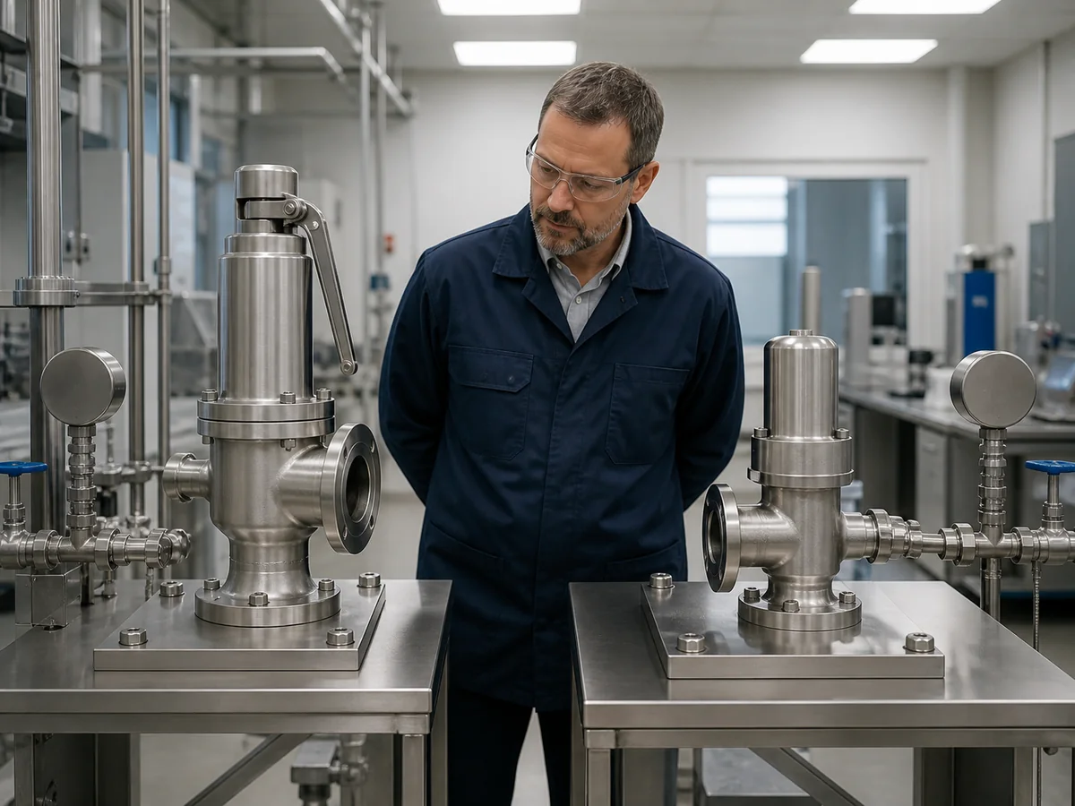
Users confuse safety valves and relief valves because many external features overlap while the important differences are internal, functional, and documentary. The same body casting may be offered with different trim, spring, nozzle, disc, lift, certification, or fluid-service options. Similar flange sizes and pressure classes can therefore conceal different effective orifices, certified capacities, and opening characteristics.
The terminology becomes more difficult when PRV, PSV, SRV, safety relief valve, pressure safety valve, and pressure relief valve are used as broad project abbreviations. A plant may label all overpressure valves as PSVs even though some devices serve gas and others serve liquid. Another project may use PRV as the umbrella term for every pressure-relieving valve.
PRV: Often used as an umbrella abbreviation for pressure relief valve or pressure-relieving device, but it can also be confused with pressure-reducing valve.
PSV: Frequently used in process plants for pressure safety valve, regardless of whether the actual device has pop or proportional behavior.
Safety relief valve: A broad combined term for a valve that may serve gas, vapor, steam, or liquid when its design and certification support the duty.
Relief valve: Commonly associated with proportional liquid-service opening.
Safety valve: Commonly associated with rapid compressible-fluid opening.
Composite engineering scenario: A project team compared two valves only by a 2-inch inlet, 3-inch outlet, similar set pressure, and the same flange class. The replacement valve physically fitted the liquid process skid, but its opening characteristic and capacity documentation were based on compressible-fluid service. The system developed pressure oscillation and hydraulic shock during testing. The cause was functional misapplication, not flange mismatch. The correction was to calculate the liquid relief case and select a liquid-certified proportional relief design.
Terminology Boundary: Common API Usage vs ISO Product Language
The gas-versus-liquid distinction is useful for process-industry communication, but it must not be presented as a universal global naming rule. In common API-oriented practice, “safety valve” is often associated with rapid opening in steam, gas or vapor service, while “relief valve” is often associated with proportional liquid service. By contrast, ISO 4126-1 specifies general product requirements for safety valves irrespective of the fluid and explicitly describes itself as a product standard rather than an application standard.
Term
Common Process-Industry Use
What the Term Does Not Prove
Datasheet Control
Safety valve
Often rapid or pop opening for compressible service.
Actual certified fluid, capacity, code route or suitability for every steam/gas application.
State fluid, opening characteristic, model, orifice, capacity basis and certification.
Relief valve
Often proportional or modulating opening for liquid service.
That the valve is unsuitable for every gas duty or approved for every liquid scenario.
State liquid properties, flashing risk, required capacity and accepted product basis.
Safety relief valve
Broad term for a reclosing device that may serve specified compressible or liquid duties.
The exact opening action, fluid certification or code marking.
Write the complete protective duty instead of relying on the combined name.
PRV / PSV
Plant abbreviations or umbrella terms.
Construction, fluid, capacity, back-pressure response or certification.
Define the full valve function; PRV can also mean pressure-reducing valve in other documents.
Procurement rule: Use the term as a search and document label. Approve the valve from the protected equipment, governing relief scenario, fluid state, opening action, required and certified capacity, back pressure, materials, installation and code route.
Safety Valve vs Relief Valve: The Real Differences That Affect Selection
Opening Action and Operating Mechanism
The most visible difference is how lift develops after the opening condition is reached, but the underlying difference is the interaction between fluid behavior and valve geometry.
In a pop-action safety valve, initial lift exposes additional disc area or huddling-chamber geometry to pressure and flowing-fluid forces. With a compressible fluid, expansion through the nozzle can rapidly increase the opening force and drive the disc toward a larger lift. This helps the valve establish a substantial flow area quickly.
In a proportional relief valve, lift generally increases with inlet pressure above the opening region. The valve progressively develops more flow area as the liquid pressure rises. This behavior can reduce abrupt liquid acceleration and can better match many hydraulic, pump, and thermal-expansion duties.
Pop action develops lift rapidly in many compressible-fluid safety valves. Proportional relief valves generally increase lift as liquid pressure rises. The actual characteristic remains product- and certification-specific.
Table: Opening Mechanism Comparison
Feature
Safety Valve
Relief Valve
Typical Lift Style
Rapid or pop opening.
Gradual or proportional opening.
Typical Fluid Behavior
Compressible steam, gas, air, or vapor.
Incompressible liquid, subject to flashing review.
Pressure Response
Moves quickly from initial lift toward a larger relieving area.
Lift generally increases with pressure above the opening region.
Primary Selection Concern
Rapid capacity development, stable lift, blowdown, and discharge reaction.
Liquid capacity, stable proportional lift, hydraulic reaction, and reseating.
Misapplication Risk
Hydraulic shock or unsuitable liquid behavior if used without liquid certification.
Insufficiently rapid or uncertified compressible-fluid performance if misapplied.
The opening characteristic cannot be confirmed from the body shape alone. The model datasheet, product standard, certified capacity data, selected trim, and manufacturer documentation must support the required duty.
Service Media and Typical Applications
Fluid phase is a primary selection input, but it must be reviewed at relieving conditions rather than copied from the normal process description.
A process normally described as liquid can flash after pressure falls through the valve. A gas system may contain liquid carryover or condensate. Steam can be saturated, superheated, or wet. These conditions affect required area, reaction forces, stability, materials, and the appropriate capacity certification.
Media phase provides the initial selection direction, but engineers must also check relieving conditions, flashing, two-phase behavior, pressure, temperature, capacity, and code route.
Typical safety-valve review cases:
Power and process steam boilers.
Steam drums, headers, and superheater systems.
Compressed-air receivers.
Gas separators and pressure vessels.
Compressor discharge and gas-process equipment.
Vapor spaces and compressible-fluid process systems.
Typical relief-valve review cases:
Hydraulic power units and skids.
Positive-displacement pump discharge.
Blocked-in liquid thermal expansion.
Liquid storage and transfer equipment.
Water, oil, chemical, and liquid-hydrocarbon process systems.
Jacketed or heat-traced liquid piping.
Industry comparison: A boiler drum and a blocked-in liquid pipeline can both experience overpressure, but their relief mechanisms are different. Steam expansion can create a large compressible-fluid load requiring rapid capacity development. A trapped liquid segment can generate high pressure from a small thermal expansion volume and may require only a relatively small liquid-relief capacity. Copying the same valve logic between these cases is not technically justified.
A capacity value is meaningful only when its test or calculation basis matches the actual relieving duty. Steam, air, process gas, liquid and two-phase capacities cannot be exchanged by comparing only a number and unit. Engineers should verify the capacity medium, relieving pressure, relieving temperature, molecular weight or density, compressibility, viscosity, back pressure and selected valve configuration.
Capacity Evidence
What to Match
Common Error
Approval Decision
Steam capacity
Steam condition, set/relieving pressure, temperature and applicable code basis.
Applying a steam-table value to gas or liquid duty.
Accept only when the selected model and steam basis cover the required load.
Air or gas capacity
Gas properties, molecular weight, compressibility, temperature and back pressure.
Treating air capacity as universal process-gas capacity.
Recalculate or use manufacturer-supported data for the actual gas.
Liquid capacity
Density, viscosity, pressure differential, overpressure basis and flashing behavior.
Using a compressible-fluid coefficient or ignoring viscosity/flashing.
Confirm a liquid-service design and accepted liquid capacity basis.
Two-phase capacity
Approved two-phase method, phase behavior and manufacturer acceptance.
Forcing the case into a single-phase gas or liquid shortcut.
Hold selection until the project calculation method is defined.
The official API 520 Part I page identifies sizing and selection as a distinct engineering activity. It does not define the plant relief scenario by itself and does not make connection size a capacity certificate.
Set Pressure, Overpressure, and Reseating Behavior
Set pressure alone does not describe the complete opening and closing cycle of either device. Engineers must also review normal operating pressure, operating margin, relieving pressure, overpressure, accumulation, blowdown or closing-pressure behavior, and the applicable equipment limit.
Set pressure: The pressure at which the valve is adjusted to begin its specified opening response.
Overpressure: The pressure increase above set pressure while the valve is relieving.
Accumulation: The pressure increase above the protected equipment’s MAWP or other allowable pressure boundary during the event.
Blowdown: The difference between set pressure and reseating pressure, commonly associated with pop-action safety valves and other reclosing pressure relief valves.
Operating margin: The separation between normal operating pressure and the valve’s opening region.
The relationship between set pressure and MAWP is controlled by the protected-equipment code, the approved relief scenario, and the adopted project edition. It should not be inferred from the valve name or copied as one universal percentage. Multiple-device, fire, boiler, and process-vessel cases may use different pressure boundaries.
Cold differential test pressure (CDTP), where specified, is a shop-test setting that accounts for defined service effects such as back pressure or temperature. It is not an independent protection limit and should not be used to justify arbitrary field adjustment. The as-left test record must remain traceable to the service set-pressure basis.
The required operating margin is not one universal percentage. It depends on valve type, seat design, service cleanliness, pressure pulsation, temperature, required tightness, manufacturer data, blowdown, and project requirements. Operating too close to set pressure can produce simmer, premature leakage, or repeated cycling.
Back pressure also affects the cycle. Superimposed back pressure exists before the valve opens. Built-up back pressure develops as flow passes through the outlet piping. Depending on valve type, it can affect opening force, lift, effective capacity, blowdown, and reseating. A conventional spring-loaded safety valve, balanced bellows valve, and pilot-operated valve should not be assumed to respond identically.
Composite engineering scenario: A steam safety valve opened at the expected set pressure but leaked after reseating. The initial assumption was seat damage from normal wear. Investigation showed that the outlet header had been modified, increasing built-up back pressure, while the operating pressure had also moved closer to set pressure. The corrective action included recalculating the outlet system, reviewing the valve configuration and operating margin, repairing the seat, and completing set-pressure and seat-tightness testing before resealing.
Design and Construction Differences
The functional distinction can be created by disc geometry, nozzle and huddling-chamber design, lift, spring characteristics, adjusting rings, guiding arrangement, and the product’s certified flow basis.
A pop-action safety valve is designed to develop rapid lift and high flow area in compressible-fluid service. A proportional relief valve is designed so lift follows increasing inlet pressure more progressively. Some safety relief valve product families use a common body with different internal trims or certifications for gas and liquid duties.
Spring-loaded and pilot-operated construction are separate from the safety-valve-versus-relief-valve naming distinction. A direct spring-loaded valve provides a comparatively direct mechanical force balance, while a pilot-operated valve can support tight shutoff, high operating-pressure ratios, or specific back-pressure behavior in suitable service. Pilot passages and sensing lines introduce additional sensitivity to dirt, condensation, freezing, polymerization, routing, and maintenance quality.
Critical components include:
Nozzle and seat: Define the pressure-sensing area, sealing surface, and flow entrance.
Disc and disc holder: Control lift, flow forces, and seat contact.
Spring: Provides the calibrated closing force and influences set pressure and reseating.
Guide and spindle: Control alignment and movement; corrosion, fouling, or galling can cause sticking.
Adjusting rings or blowdown components: Influence opening and reseating behavior in applicable designs.
Bellows: Can reduce back-pressure influence but introduces material, fatigue, and bonnet-vent requirements.
Soft or metal seat: Changes tightness, temperature capability, chemical compatibility, and maintenance behavior.
Table: Construction and Functional Intent
Design Aspect
Safety Valve Tendency
Relief Valve Tendency
Opening Geometry
Designed to encourage rapid lift or pop action.
Designed to develop proportional lift with pressure.
Typical Certification Fluid
Steam, gas, air, or vapor, depending on product.
Liquid, depending on product and standard.
Flow Development
Large flow area develops quickly after initial lift.
Flow area generally increases progressively.
Reseating
Often defined by a measurable blowdown below set pressure.
Closing response follows falling liquid pressure and product design.
Primary Misapplication Risk
Unsuitable hydraulic response, shock, or lack of liquid certification.
Unsuitable compressible-fluid opening or insufficient certified gas/steam capacity.
Expert note: Material and construction review must extend beyond the body. The nozzle, disc, seat, guide, spindle, spring, bellows, gasket, and soft parts can each control corrosion resistance, leakage, sticking, and service life.
Can a Safety Valve Replace a Relief Valve or Vice Versa
Substitution requires verification of the complete protective duty. Matching size, pressure class, and set pressure is not sufficient.
When Interchangeability Creates Risk
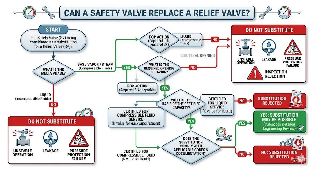
A safety valve and a relief valve should not be treated as automatically interchangeable, but substitution may be possible when the proposed valve is specifically designed, sized, tested, documented, and approved for the actual duty.
The correct answer is therefore not a universal “never,” but it is also not “yes if the connections match.” The proposed device must provide the required opening characteristic and certified capacity for the fluid and relieving conditions. Its set pressure, pressure-temperature rating, materials, seat tightness, back-pressure tolerance, installation, and code route must also be acceptable.
Common high-risk substitutions include:
Using a liquid-only relief valve on steam or gas service without compressible-fluid certification.
Using a gas-oriented pop-action valve on a hydraulic system without liquid certification or hydraulic-stability review.
Replacing an ASME boiler safety valve with a general process relief valve.
Replacing a balanced bellows valve with a conventional valve while retaining a high-back-pressure outlet system.
Replacing a pilot-operated valve with a spring-loaded valve without reviewing operating margin, capacity, and back pressure.
Approving a replacement from set pressure and flange size without checking the effective orifice and certified capacity.
Composite engineering scenario: A buyer proposed replacing a boiler safety valve with a general liquid relief valve because the inlet size, outlet size, set pressure, and pressure class matched. Engineering rejected the substitution because the replacement had no appropriate steam-capacity certification, different opening behavior, and no support for the boiler code route. The problem was not product quality or physical fit. It was a mismatch in protection duty and certification.
Composite engineering scenario: After a process debottlenecking project, maintenance ordered a dimensionally identical replacement pressure relief valve. The new valve had the correct set pressure but a smaller effective orifice and insufficient certified capacity for the revised blocked-outlet case. The error was discovered during final technical review. The prevention was to revalidate required relieving capacity whenever process throughput or relief scenarios change.
What Users Should Verify Before Substitution
Substitution should be treated as a new engineering selection unless documented interchangeability has already been approved for the exact models and service.
Buyer Review Checklist Before Any Substitution
Review Item
Why It Matters
Required Evidence
Protected equipment and relief scenario
Defines what the device must protect and what causes the pressure rise.
Relief calculation, equipment datasheet, or approved design basis.
Fluid composition and phase
Determines sizing method, opening characteristic, materials, and capacity basis.
Process composition and relieving-condition data.
Required relieving capacity
Defines the minimum flow needed to protect the equipment.
Approved calculation for the governing case.
Certified or accepted capacity
Confirms the proposed valve can pass the required flow.
Certified capacity data, manufacturer report, or approved capacity basis.
Set pressure, overpressure, and accumulation
Controls opening and the allowable pressure rise during relief.
Code basis and approved datasheet.
Operating margin and blowdown
Affect leakage, simmer, cycling, and process recovery.
Manufacturer data and operating envelope.
Back pressure
Can affect opening force, capacity, blowdown, and reseating.
Superimposed and built-up back-pressure calculation.
Materials and seat type
Control corrosion, temperature capability, tightness, and life.
Material specification and certificates where required.
Inlet and outlet piping
Control pressure loss, stability, discharge reaction, and safe disposal.
Installation drawing and engineering review.
Applicable code and certification
Determines legal, owner, and inspection acceptance.
Nameplate, certification, exact standard, and edition.
Maintenance and repair pathway
Ensures the valve can be tested and repaired under the required quality system.
Maintenance plan, repair authorization, and test procedures.
Passing one test does not prove that a safety valve and a relief valve are interchangeable. Set-pressure, seat-tightness, capacity and installation evidence answer different questions and must remain traceable to the exact model and service.
Evidence
What It Supports
What It Cannot Prove Alone
Set-pressure / CDTP record
Opening adjustment under the recorded test conditions.
Full lift, certified capacity, fluid suitability or field stability.
Required capacity, correct set-pressure basis or suitability of installed piping.
Certified or accepted capacity
Supported relieving performance for a defined model, fluid and condition.
That the process relief calculation or outlet system is correct.
Nameplate and marking
Valve identity, set pressure and certification information within the marking scope.
That the current process duty is unchanged or that a same-size replacement is equivalent.
As-found / as-left report
In-service condition and final workshop condition.
That an incorrect valve type, orifice or discharge system has been corrected.
Where ASME/National Board certification is part of the project route, the National Board NB-18 database can be used to verify certified manufacturers, assemblers and device types. The listing must still be matched to the exact manufacturer, design, valve configuration and capacity basis.
Comparison Table: Safety Valve vs Relief Valve
Side-by-Side Functional Comparison
The following comparison reflects common API and process-industry terminology. Product-specific documentation and the governing project standard still control the final classification.
Feature
Safety Valve
Relief Valve
Typical Opening Style
Rapid or pop opening.
Gradual or proportional opening.
Usual Fluid Service
Steam, gas, air, or vapor.
Liquid.
Primary Function
Overpressure protection with rapid capacity development.
Overpressure protection with progressive liquid relief.
Typical Applications
Boilers, steam systems, gas vessels, air receivers, and compressor systems.
Hydraulic systems, pumps, liquid piping, storage, and thermal expansion.
Lift Development
Large lift develops rapidly after initial opening.
Lift generally increases as inlet pressure rises.
Closing Behavior
Typically reseats below set pressure through a defined blowdown range.
Lift reduces as liquid pressure falls before reseating.
Capacity Evidence
Must support the specified steam, gas, or vapor duty.
Must support the specified liquid duty.
Back-Pressure Sensitivity
Depends on conventional, balanced, or pilot-operated construction.
Depends on design, discharge system, and liquid flow conditions.
Primary Misapplication Risk
Unsuitable liquid behavior, hydraulic shock, or lack of liquid certification.
Unsuitable compressible-fluid response or insufficient gas/steam capacity.
Connection Size
Confirms physical interface only.
Confirms physical interface only.
Interchangeability
Only after complete engineering, capacity, certification, material, installation, and code review.
Quick user rule: For steam, gas, air, or vapor, begin with a safety-valve or compressible-fluid safety-relief-valve review. For liquid, begin with a liquid-certified relief-valve review. Then verify the exact product design and complete duty.
How to Choose the Right Valve for Your System
Selection Factors Users Should Review First
The correct valve is selected from the overpressure scenario and system conditions, not from the catalog name or existing connection size.
Users should review the following sequence:
Identify the protected equipment: Boiler, pressure vessel, pump, piping segment, hydraulic skid, storage equipment, or another pressure boundary.
Define the governing relief scenario: Blocked outlet, external fire, control failure, tube rupture, gas blowby, pump deadhead, thermal expansion, or another credible event.
Confirm the medium and phase: Steam, gas, vapor, liquid, flashing liquid, or two-phase flow at relieving conditions.
Establish pressure limits: Operating pressure, MAWP or other allowable limit, set pressure, allowable overpressure or accumulation, and blowdown requirement.
Calculate required relieving capacity: Use the approved sizing method for the governing case.
Verify certified capacity: Confirm the selected model, effective orifice, coefficient, fluid, pressure, temperature, and configuration provide enough documented capacity.
Review back pressure: Determine superimposed and built-up outlet pressure.
Maintenance teams: Seat leakage, access, lifting arrangements, spare parts, test capability, repair route, and reinstatement controls.
Inspectors: Code marking, nameplate, set pressure, capacity basis, material traceability, test records, seals, and repair authorization.
A technically correct valve that cannot be safely removed, tested, repaired, or reinstated creates lifecycle risk. Likewise, a valve that is easy to purchase and maintain but lacks enough certified capacity is not an acceptable solution.
Return-to-Service After Repair or Valve-Type Change
A repaired valve or an approved substitute should not return to service on the strength of a workshop set-pressure result alone. The release package should connect the repaired or replacement device to the approved duty and installed system.
Record the as-found set pressure, leakage, contamination, corrosion, seal condition and identity.
Confirm the approved model, trim, spring range, seat type, orifice and material configuration.
Complete the required as-left set-pressure, seat-tightness and functional tests.
Restore nameplate traceability, adjustment seals and repair documentation.
Verify inlet cleanliness, inlet pressure loss, outlet support, drainage, back pressure and installation orientation.
Close the root cause of chatter, corrosion, contamination, thermal distortion or repeated leakage.
Update the plant register, datasheet, relief calculation and management-of-change record when the type or duty changed.
Where the owner or jurisdiction requires an authorized repair route, the National Board VR program and the adopted NBIC requirements control the repair organization’s authorization, quality management system, testing, marking, and documentation scope. The 2025 NBIC places pressure-relief-device repair and conversion requirements in Part 4. VR authorization does not replace relief sizing, capacity confirmation, management of change, or installed-system review.
Common Mistakes When Comparing Safety Valves and Relief Valves
Choosing by Name, Size, or Pressure Class Only
The most common mistake is treating the catalog name, flange size, or pressure class as proof that the valve is suitable.
Pressure class confirms a pressure-temperature rating for the specified body material and connection standard. Inlet and outlet sizes confirm the physical interface. Neither proves:
The effective orifice area.
The certified relieving capacity.
The opening characteristic.
The approved fluid or phase.
The blowdown or closing behavior.
The back-pressure tolerance.
The material compatibility of internal components.
The code or certification route.
A larger connection does not necessarily provide more capacity, and a larger effective orifice is not automatically safer. Excessive oversizing can contribute to unstable lift and chatter when the process cannot sustain the selected valve’s flow demand.
Composite engineering scenario: A chemical plant replaced a corroded valve with the same nominal size and a stainless-steel body. Leakage returned within one operating cycle. The body remained sound, but chloride attack had damaged the nozzle, disc, and guide materials, which had not been upgraded. The correction was to specify complete wetted-trim and guiding-component materials instead of using body material as the only compatibility criterion.
Ignoring Media Phase and Flow Behavior
Gas, vapor, steam, liquid, flashing liquid, and two-phase mixtures do not produce the same force, lift, sizing, or discharge behavior.
A normal-process label can also be misleading. A liquid may flash at the valve inlet or nozzle because the relieving pressure falls below its bubble point. A gas stream may carry liquid droplets, solids, wax, or condensate. Steam can contain water or become superheated. These conditions affect valve type, sizing method, material selection, stability, and outlet design.
Ignoring the phase can cause:
Use of an incorrect sizing equation or coefficient.
Selection of an unsuitable opening characteristic.
Insufficient certified capacity.
Chatter or unstable lift.
Hydraulic shock or excessive reaction force.
Unexpected flashing, noise, vibration, or outlet back pressure.
Seat erosion and post-operation leakage.
Composite engineering scenario: A liquid process duty was reviewed using compressible-fluid assumptions because the upstream stream contained dissolved gas. The selected valve produced unstable pressure response and repeated maintenance complaints. Reanalysis showed that the controlling flow at the valve was flashing two-phase service, not clean gas or incompressible liquid. The correction required an approved two-phase sizing method and a valve accepted for the actual relieving conditions.
Failure Patterns That Point to Misapplication
The observed symptom should be traced back to the complete valve duty rather than treated as a seat problem by default.
Observed Symptom
Possible Engineering Cause
Review / Corrective Direction
Chatter or rapid cycling
Oversizing, excessive inlet loss, high built-up back pressure, wrong opening characteristic or insufficient sustainable flow.
Recheck the relief case, selected orifice, inlet line and outlet system.
Hydraulic shock
Pop-action valve applied to liquid duty, abrupt discharge routing or trapped liquid.
Confirm liquid-service design, proportional behavior and discharge piping.
Persistent leakage after lift
Seat damage, contamination, poor operating margin, thermal distortion, back pressure or incorrect reseating behavior.
Compare as-found condition with installed pressure and piping data before lapping or replacement.
Revalidate the governing relief load and capacity evidence.
Pilot response delay
Dirty, freezing, polymerizing or wet service affecting pilot passages and sensing lines.
Review direct spring-loaded alternatives, filtration, heating, drainage and maintenance access.
Early corrosion or sticking
Body material selected correctly but nozzle, disc, guide, spring, bellows or seals are incompatible.
Specify component-level materials and damage mechanisms.
Overlooking Standards and Documentation Requirements
A technically plausible valve can still be unacceptable if the certification, capacity evidence, testing, materials, and repair pathway do not match the project requirements.
Generic statements such as “ASME compliant,” “API valve,” or “ISO safety valve” are not enough. The technical offer should identify the exact product standard, code marking, edition where required, fluid capacity basis, set pressure, model, materials, tests, and supplied records.
Table: Documentation Users Should Check
Document or Data
What It Verifies
Approved datasheet
Protected equipment, fluid, pressure, temperature, set pressure, materials, and project requirements.
Relief calculation
Governing scenario, required relieving capacity, relieving conditions, and required area.
Certified or accepted capacity data
That the selected valve and orifice can satisfy the required flow for the stated fluid basis.
Nameplate and model details
Valve identity, size, set pressure, certification markings, and traceability.
Set-pressure test record
Opening adjustment under the specified test procedure.
Seat-tightness test record
Leakage performance under the applicable acceptance method.
Material certificates
Traceability of specified body, bonnet, nozzle, disc, spring, bellows, and other components.
Installation manual
Orientation, back-pressure limits, inlet and outlet requirements, venting, drainage, and handling.
Repair and calibration history
Previous defects, replaced parts, adjustment, testing, seal status, and return-to-service basis.
Inspection and release documentation
Completion of purchaser, third-party, or regulatory inspection requirements.
After disassembly, adjustment, or repair, the valve should be recalibrated, seat-tested, documented, and resealed according to the applicable quality system and jurisdiction. Where a recognized pressure-relief-valve repair authorization is required, the National Board VR route may apply. For a lifecycle workflow, review the safety valve maintenance and inspection guide.
Codes and Standards That Matter in This Comparison
ASME, API, and ISO Basics
Each standard has a different function. No single document covers every aspect of relief scenario definition, sizing, product construction, installation, testing, certification, inspection, and repair.
2025 NBIC; pressure-relief-device repair and conversion requirements are addressed in Part 4.
In-service inspection and authorized repair framework where adopted by the jurisdiction or owner.
Repair authorization controls the repair route; it does not replace original sizing, selection, or system revalidation.
The purchased project edition, protected-equipment code, owner specification, and local regulatory adoption control. Current public pages show a 2025 ASME BPVC edition, API 520 Part I 10th Edition, API 520 Part II 7th Edition, API 521 7th Edition, API 526 8th Edition, API 527 5th Edition, API RP 576 5th Edition, and ISO 4126-1:2013 / ISO 4126-4:2013 confirmed current in 2025. A quotation should still identify the exact adopted edition, addenda, errata, marking, capacity basis, and jurisdiction instead of using a generic “ASME/API/ISO compliant” statement.
ISO 4126-1 applies to safety-valve products irrespective of fluid, which is why the gas-versus-liquid distinction should be described as a common API and industry usage pattern rather than a universal global definition. Product design, test certification, and application data remain decisive.
Authoritative Evidence Hierarchy for Technical Approval
Technical approval should use the most specific evidence available and should not rely on a generic compliance phrase.
Evidence Level
Examples
Approval Use
Project and jurisdiction basis
Protected-equipment code, owner specification, local regulation and approved relief philosophy.
Defines the legal and technical acceptance route.
Approved engineering calculation
Relief scenario, required load, relieving conditions, back pressure and required area.
Defines what the pressure relief device must accomplish.
Shows whether the selected device can meet the approved duty.
Order-specific test and material records
Set pressure, seat tightness, material certificates, nameplate and inspection release.
Shows that the supplied serial-numbered valve matches the order.
Installation and lifecycle records
Inlet/outlet review, as-found/as-left reports, repair authorization and return-to-service record.
Shows that the installed and maintained system remains acceptable.
The 2025 edition of ASME BPVC Section XIII provides rules for overpressure protection of boilers, pressure vessels and piping systems and includes requirements for pressure-relief-device design, material, inspection, assembly, testing and marking. It does not replace the protected-equipment section or project-specific relief calculation.
Why Standards Affect Buyer Decisions, Not Just Compliance
Standards determine what evidence is required to show that the valve can perform the intended protective function.
They separate sizing and selection from installation review.
They distinguish set-pressure testing from seat-tightness testing and capacity certification.
They connect the valve to the protected equipment’s allowable pressure boundary.
They establish product marking, certification, inspection, and repair requirements.
They prevent a similar-looking valve from being accepted without proof of the correct fluid and capacity basis.
They help maintenance teams decide whether a valve can be adjusted locally or must be repaired under an authorized quality system.
A code-marked or standard-compliant valve can still be misapplied if the relief scenario, required capacity, medium, materials, back pressure, or installed piping are incorrect. Compliance and application engineering must support the same duty.
The difference between a safety valve and a relief valve is not merely a naming preference. It describes a common difference in opening behavior and typical fluid service that can directly affect system protection. Safety valves are commonly associated with rapid opening in steam, gas, air, or vapor service. Relief valves are commonly associated with proportional opening in liquid service. Safety relief valves may cover either duty when their design and certification support it.
Users should not choose between them by name, connection size, pressure class, or body material alone. The final decision must address the protected equipment, relief scenario, fluid state, set-pressure basis, required and certified capacity, back pressure, materials, installation, testing, and applicable code route.
Final Buyer Check Before Selection
Checklist Item
Decision Question
Protected Equipment
What exact pressure boundary must the valve protect?
Relief Scenario
What credible event creates the required relieving load?
Fluid and Phase
Is the relieving flow steam, gas, vapor, liquid, flashing liquid, or two-phase?
Opening Characteristic
Does the duty require rapid pop action or proportional liquid lift?
Pressure Basis
Do set pressure, overpressure, accumulation, and operating margin match the protected equipment and code?
Capacity
Does certified or project-accepted capacity meet the calculated required load?
Back Pressure
What superimposed and built-up back pressure will the valve experience?
Materials
Are the body, nozzle, disc, guide, spring, bellows, gasket, and seat compatible?
Installation
Are inlet loss, outlet resistance, support, drainage, orientation, and discharge routing acceptable?
Documents
Does the supplied package support the exact code, testing, certification, and repair requirements?
A disciplined engineering review leads to more reliable pressure protection, fewer leakage and chatter problems, lower lifecycle cost, and stronger technical and regulatory acceptance.
Engineering review note: This article supports technical education and preliminary selection. Final approval must use the protected equipment, governing relief scenario, actual relieving fluid state, required capacity, selected model data, installed piping, adopted code edition, and jurisdiction.
FAQ
What is the main difference between a safety valve and a relief valve?
In common API and process-industry usage, a safety valve is associated with rapid or pop opening in steam, gas, air, or vapor service, while a relief valve is associated with gradual or proportional opening in liquid service. This is a practical starting distinction rather than a universal naming rule. The product design, fluid certification, required capacity, and governing standard must confirm the final selection.
Can a safety valve be used for liquid systems?
Yes, but only when the specific valve design is suitable, sized, tested, documented, and approved for liquid service. Do not assume that a gas- or steam-certified pop-action safety valve is acceptable for liquid merely because the size and pressure rating match. ISO and some manufacturer terminology may use “safety valve” more broadly than common API terminology.
How often should safety valves be tested or replaced?
There is no universal inspection, test, or replacement interval suitable for every valve. The interval depends on the governing regulation, owner program, service severity, corrosion, contamination, operating cycles, consequence of failure, and previous test history. Abnormal lift, severe chatter, fire exposure, process change, or unexplained leakage can justify earlier inspection.
What certifications should buyers look for in safety or relief valves?
Buyers should look for the certification and documentation required by the protected equipment, jurisdiction, owner specification, and project standard. This may include applicable ASME marking, certified capacity data, API or ISO product requirements, set-pressure records, seat-tightness tests, material certificates, inspection records, and an approved repair route.
Why do datasheets sometimes list both valves under similar specifications?
Body style, connections, pressure class, and materials can overlap even when the internal trim, opening characteristic, certified capacity, and fluid-service basis differ. The buyer should check the model configuration, effective orifice, certified fluid, seat type, blowdown, back-pressure limits, and applicable standard rather than compare only the visible data.
Can a relief valve be used for steam or gas service?
Only when the specific device is designed, certified, and approved for the compressible-fluid duty. A liquid-only proportional relief valve should not be used as an automatic substitute for a steam or gas safety valve. The required opening behavior, certified capacity, code route, materials, and discharge system must be verified.
What is a safety relief valve?
A safety relief valve is a broad term for a reclosing pressure-relieving valve that may be suitable for gas, vapor, steam, or liquid depending on its design and application. The term alone does not prove whether the valve has pop or proportional opening or whether it is certified for the required fluid. The datasheet must state the actual duty.
What is the difference between set pressure and overpressure?
Set pressure is the pressure at which the valve is adjusted to begin its specified opening response. Overpressure is the pressure increase above set pressure while the valve is relieving. Accumulation is referenced to the protected equipment’s MAWP or allowable pressure boundary, while blowdown is the difference between set pressure and reseating pressure.
Why is certified relieving capacity more important than connection size?
Connection size confirms physical fit, while certified relieving capacity confirms how much flow the selected valve can pass under defined conditions. Two valves with identical connections can have different effective orifices, coefficients, lift, capacity, fluid certification, and application limits.
How does back pressure affect safety valves and relief valves?
Back pressure can affect opening force, lift, effective capacity, blowdown, and reseating, depending on valve design. Superimposed back pressure exists before opening, while built-up back pressure develops during discharge. Conventional, balanced bellows, and pilot-operated designs can have different back-pressure limits and correction requirements.
When should a pilot-operated valve be considered?
A pilot-operated valve may be considered when tight shutoff, high operating-pressure ratio, large capacity, or specific back-pressure behavior justifies it. Cleanliness, pilot-line routing, condensation, freezing, fouling, materials, maintenance capability, and project acceptance must also be reviewed. A pilot-operated design is not automatically more suitable for dirty or polymerizing service.
Does API 527 prove that a valve has enough relieving capacity?
No.API 527 addresses seat tightness for applicable pressure relief valves. A passing leakage result does not prove required capacity, correct set pressure selection, suitable fluid certification or acceptable installed piping.
Can same-size safety valves and relief valves be interchangeable?
Not by size alone. Same-size valves can have different effective orifices, opening characteristics, fluid certifications, capacity, materials, blowdown and back-pressure limits. Interchangeability requires model-specific engineering approval.
What causes chatter after replacing a pressure relief valve?
Common causes include oversizing, excessive inlet pressure loss, increased built-up back pressure, wrong opening characteristic, insufficient sustainable process flow or mechanical piping load. The relief calculation and installed inlet/outlet system should be reviewed before treating chatter as a simple adjustment problem.
How should flashing or two-phase relief service be classified?
It should not be forced into a simple gas-versus-liquid label. Use the project-approved two-phase sizing method, actual thermodynamic state, relieving pressure and temperature, outlet pressure and manufacturer acceptance for the selected valve.
What should be checked after a safety or relief valve is repaired?
Check the approved model and trim, replacement parts, spring range, seat condition, as-left set pressure, seat tightness, nameplate, seal, installation condition and repair documentation. Also close the system cause of corrosion, contamination, chatter or repeated leakage before return to service.
What does National Board NB-18 verify?
NB-18 provides searchable certification information for pressure relief device manufacturers, assemblers and certified device types. It supports certification checks but must be matched to the exact manufacturer, model, configuration and capacity basis.
Is a pressure relief valve the same as a pressure-reducing valve?
No. A pressure relief valve opens during an abnormal overpressure condition to protect equipment. A pressure-reducing valve regulates downstream pressure during normal operation. Because both may be abbreviated PRV, datasheets and tags should write the full function.
Related Engineering Guides
Continue with these focused guides when the engineering review reaches the corresponding sizing, selection, installation, or maintenance question:
To provide the best experiences, we use technologies like cookies to store and/or access device information. Consenting to these technologies will allow us to process data such as browsing behavior or unique IDs on this site. Not consenting or withdrawing consent, may adversely affect certain features and functions.
Functional
Always active
The technical storage or access is strictly necessary for the legitimate purpose of enabling the use of a specific service explicitly requested by the subscriber or user, or for the sole purpose of carrying out the transmission of a communication over an electronic communications network.
Preferences
The technical storage or access is necessary for the legitimate purpose of storing preferences that are not requested by the subscriber or user.
Statistics
The technical storage or access that is used exclusively for statistical purposes.The technical storage or access that is used exclusively for anonymous statistical purposes. Without a subpoena, voluntary compliance on the part of your Internet Service Provider, or additional records from a third party, information stored or retrieved for this purpose alone cannot usually be used to identify you.
Marketing
The technical storage or access is required to create user profiles to send advertising, or to track the user on a website or across several websites for similar marketing purposes.