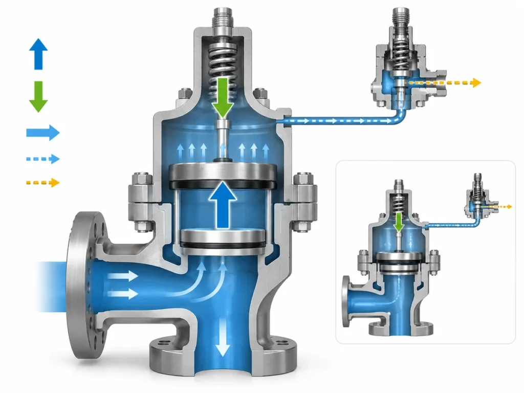
Learn what a full lift safety valve means, how it differs from low lift and full bore, why the label does not prove capacity, and what to verify before selection.

A full lift safety valve is a safety valve designed to lift far enough that disc position no longer determines the available discharge area. Once full lift is reached, the opening between the disc and seat is no longer the limiting flow restriction. The term describes a lift-and-flow-area characteristic; by itself, it does not prove relieving capacity, code compliance, or suitability for a particular relief duty.
That distinction matters when reading datasheets and RFQs. “Full lift” tells you something specific about how the valve opens and how its flow area develops, but it does not describe the rest of the valve. For broader terminology, see what a safety valve is.
What Does “Full Lift” Mean in a Safety Valve?
The engineering meaning becomes clearer when you look at the flow geometry between the disc and seat.
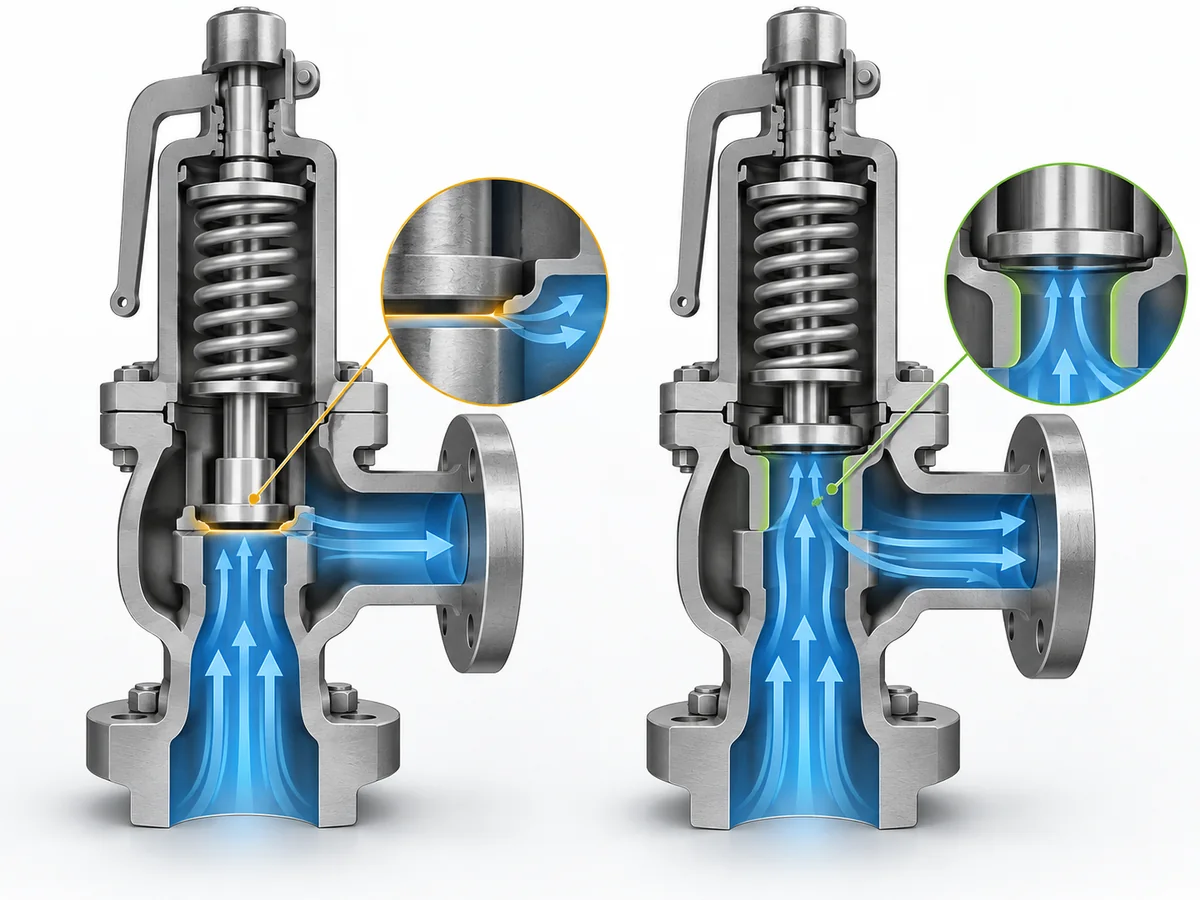
As a safety valve opens, the disc moves away from the seat. The gap between the seating surfaces forms an opening through which fluid can pass. Pressure-relief-valve engineering terminology commonly describes this opening as the curtain area and distinguishes it from the bore area and actual discharge area.
In common safety-valve engineering usage, a valve has reached full lift when the disc has travelled far enough that this curtain opening is no longer what limits the discharge area. Spirax Sarco uses the same practical distinction: in a low-lift valve, disc position determines the discharge area; in a full-lift valve, it does not.
Spirax Sarco safety-valve technical guidance
This is more precise than saying that a full lift safety valve simply “opens completely.” The useful question is whether further disc travel would still increase the controlling flow area.
“Full lift” is therefore one technical characteristic of the valve, not shorthand for its capacity, pressure class, certification, bonnet design, lifting device, or suitability for a particular process.
What Changes as a Safety Valve Reaches Full Lift?
At the start of opening, the gap between the disc and seat is relatively small. The curtain area created by that gap can therefore be the controlling restriction in the flow path. As the disc rises, the curtain area increases.
In a full-lift design, the disc eventually travels far enough that the curtain opening is no longer the smallest effective flow restriction. Further travel then stops increasing the discharge area in the same way, because another fixed part of the internal flow path—commonly the bore or another minimum passage—controls the available area.
Engineering sequence:
disc rises → curtain area increases → curtain area stops being the limiting flow area → a fixed internal flow area becomes controlling.
This is the hydraulic reason “full lift” means more than visible disc movement. It does not mean disc lift alone determines how much mass or volume the valve can relieve. Available flow area is only one part of relieving performance; valve design, relieving conditions, and the applicable capacity basis still matter.
Full Lift vs Low Lift: What Is the Practical Difference?
The clearest comparison is not “large opening versus small opening.” It is whether the disc-to-seat opening still controls the discharge area.
| Characteristic | Low Lift | Full Lift |
|---|---|---|
| Does disc position still affect the available discharge area? | Yes | Not after the full-lift condition is reached |
| Can the curtain area remain the controlling restriction? | Yes | No, once full lift is reached |
| Does the label by itself prove adequate capacity for the project? | No | No |
Spirax Sarco distinguishes low lift from full lift on this basis. In its technical explanation, disc position determines discharge area in a low-lift valve, while it no longer does so once a full-lift valve reaches full lift.
A low-lift valve does not travel far enough for the disc-to-seat opening to cease being part of the controlling flow restriction. A full-lift design travels farther, allowing the curtain area to grow beyond that controlling point.
That does not make full lift automatically “better.” The terms describe different lift and flow-area conditions. The correct valve still has to satisfy the required relief duty, service conditions, and project requirements.
Nor should the distinction be turned into a blanket service rule such as “full lift is always for gas” or “low lift is only for liquids.” Fluid phase matters in safety-valve selection, but it cannot be determined from lift classification alone.
Full Lift Is Not the Same as Full Bore, Pop Action, or Other Valve Features
Specifications often place several valve descriptors next to one another. They do not all describe the same design characteristic.
Full Lift vs Full Bore
Full lift describes the relationship between disc travel and the controlling discharge area. Full bore describes the geometry of the internal flow passage.
Spirax Sarco treats these as separate definitions: a full-lift valve is one in which disc position no longer determines the discharge area, while a full-bore valve is defined through the internal bore and the location of the controlling orifice.
Full lift ≠ full bore.
Using the terms interchangeably can create the wrong assumption about internal geometry or available flow area.
Full Lift vs Pop Action
Pop action describes how the valve moves open; full lift describes the lift condition it reaches.
In a spring-loaded safety valve, pressure acting on the valve geometry can cause rapid opening once the valve starts to relieve. LESER describes this as opening rapidly with a “pop” and notes that full lift is reached in most cases rather than defining pop action itself as full lift.
LESER spring-loaded safety valve guidance
For more detail on the force and opening sequence, see
how a spring-loaded safety valve works.
- Pop action describes opening behavior.
- Full lift describes the lift/discharge-area condition reached.
The two can be related without being synonyms.
Full Lift vs Spring, Bonnet, Lever, Bellows, or Pressure-Class Descriptions
A valve specification may also include terms such as spring-loaded, balanced or bellows, enclosed bonnet, lifting lever or spanner, or high-pressure construction. These describe other parts of the design.
The ZOBAI product catalog illustrates the distinction: different product names combine full lift with separate descriptors such as enclosed, with spanner, and high pressure.
A buyer should therefore treat “full lift” as one field in the technical description, not as a summary of the complete valve configuration.
Why “Full Lift” Alone Does Not Prove Relieving Capacity
A full-lift designation does not prove that a valve can relieve the required load for a particular system.
How much capacity does the protected system require?
The required relieving load comes from the protected equipment and the governing overpressure scenario. It does not come from the valve catalog.
Can the candidate valve provide that capacity under the required conditions?
That requires performance evidence for the specific valve and capacity basis.
ASME’s current PTC 25-2023 addresses performance testing of pressure-relief devices, including flow-capacity testing under defined inlet and outlet conditions. Capacity testing is therefore separate from assigning a design label such as “full lift.”
ASME Pressure Relief Devices Performance Test Code
The National Board likewise publishes methods for determining certified relieving capacities. That capacity basis is established independently rather than inferred from the words in a product name.
National Board certified relieving capacity guidance
For the actual sizing workflow, ZOBAI’s
Safety Valve Sizing and Certified Relieving Capacity Guide
separates required relieving capacity, relieving conditions, orifice selection, and certified-capacity verification instead of treating connection size or lift terminology as a substitute for sizing.
A valve can therefore be genuinely full lift and still be the wrong capacity for a specific relief case.
Does “Full Lift” Mean the Same Thing in Every Standard?
Not necessarily. Safety-valve terminology is used across different standards, codes, and manufacturer engineering systems. The underlying concepts can overlap without the formal wording being identical.
A numerical threshold or definition taken from one source should therefore not automatically be turned into a global rule.
ASME currently lists PTC 25-2023 as its Pressure Relief Devices Performance Test Code.
ASME PTC 25
ISO lists ISO 4126-1:2013 as the current edition of its safety-valve product standard and notes that the edition was confirmed again in 2025. ISO also states that Part 1 is a product standard rather than an application standard for selecting safety valves for individual installations.
ISO 4126-1
It is useful to separate two levels of meaning:
-
General engineering interpretation:
a full-lift safety valve reaches a condition where further disc position no longer controls the available discharge area. -
Project-specific formal interpretation:
the governing code, standard, specification, and applicable edition determine the terminology and acceptance criteria used for that project.
This article deliberately does not turn a single lift-to-bore ratio into a universal definition. Technical guides may use geometric descriptions of that type, but the applicable project basis should control when formal classification matters.
Referencing a standard also does not by itself prove that a particular valve is correctly sized, certified for the required scope, or suitable for a particular installation.
What Should You Verify When a Valve Is Described as Full Lift?
Seeing full lift on a datasheet is a useful starting point, not a complete selection decision.
Before approving a candidate valve or preparing an RFQ, verify the following:
-
Terminology and code basis.
Confirm which project specification, standard, or manufacturer terminology is being used when the valve is called full lift. -
Required relieving duty.
Establish the relieving capacity required by the protected system for the governing relief case. -
Capacity evidence.
Check the rated, certified, or otherwise documented capacity basis for the specific candidate valve and the conditions to which that capacity applies. -
Set and relieving conditions.
Confirm the relevant pressure basis used for opening and capacity evaluation. -
Fluid and phase.
Identify whether the relief duty involves gas, vapour, steam, liquid, or another defined state. The words “full lift” do not answer that question. -
Temperature.
Verify the applicable operating and relieving temperature against the selected valve configuration and materials. -
Back pressure.
Determine whether outlet or back-pressure conditions affect the required configuration or performance basis. -
The rest of the valve configuration.
Confirm spring-loaded or other actuation, conventional or balanced construction where relevant, bonnet arrangement, lifting device, materials, seat construction, connections, and any project-required documentation separately.
These variables are consistent with established pressure-relief-valve sizing and selection workflows. Emerson’s PRV2SIZE platform, for example, separately asks for fluid properties, pressure and back pressure, temperature, and flow capacity before valve configuration is completed.
Emerson PRV2SIZE overview
For a buyer, the useful shift is from asking “Do you have a full lift safety valve?” to asking whether a particular full-lift candidate satisfies the required relief duty, service conditions, configuration, and documentation basis for the project.