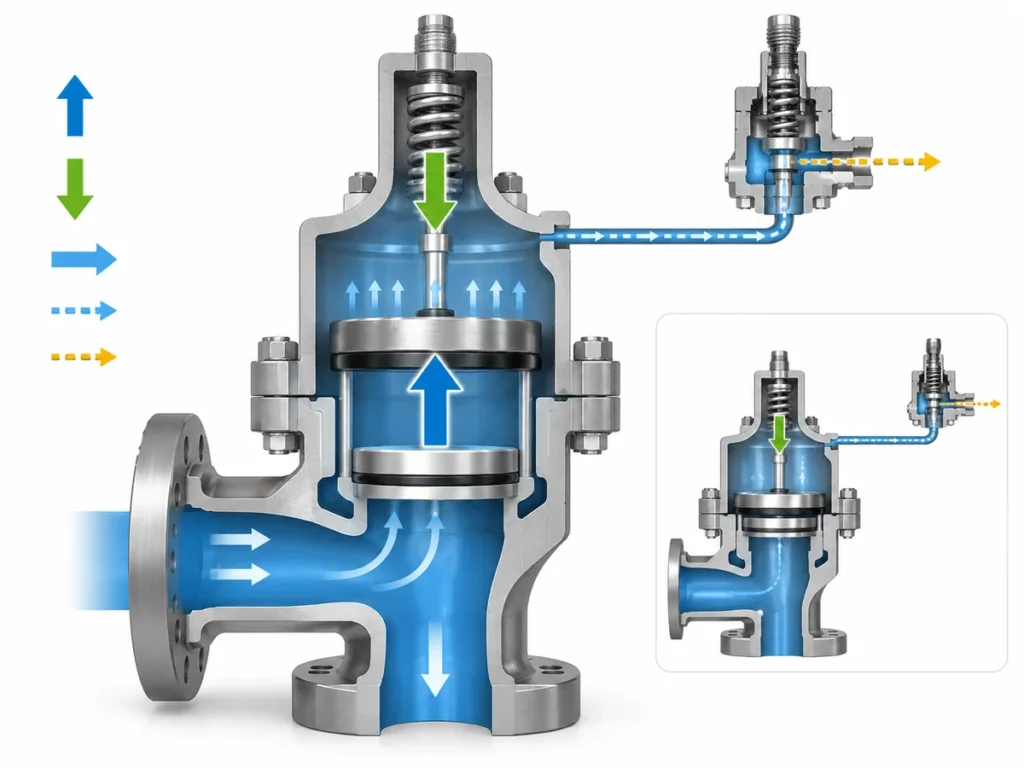
Learn how compressor pulsation, pilot sensing, remote sensing and blowdown affect POSRV stability, reseating and engineering/RFQ review.

A pilot-operated pressure relief valve can be a candidate for compressor overpressure protection, but compressor service raises questions that a static datasheet does not answer. The most important is often simple to state:
What pressure is the pilot actually seeing when the compressor system is pulsating, the relief valve is flowing, or pressure is recovering after a relief event?
That question links three issues—pressure dynamics, sensing, and blowdown/reseating.
A valve can have an appropriate set-pressure basis and required relieving capacity yet still need further engineering review if the pilot receives an unrepresentative pressure signal, the inlet arrangement creates problematic pressure loss, or the valve’s closing behavior does not fit the compressor’s operating pressure envelope.
For that reason, a compressor POSRV review should not start by asking which pilot design is “best.” Start by identifying the pressure phenomenon, then trace the pressure signal to the pilot, review the main-valve flow path, and finally check how the selected architecture opens and reseats.
Separate Compressor Pulsation From Valve-Induced Cycling
Not every unstable pressure trace around a compressor relief valve is the same problem. Compressor-generated pulsation, a short pressure spike, and cycling associated with the relief valve’s inlet or sensing arrangement can look similar while requiring different checks.
Reciprocating compressors can create pressure pulsations in connected suction and discharge systems. A short pressure spike is different: it may be a transient excursion toward the set condition rather than a repeating pressure pattern.
A separate mechanism can appear after a relief valve begins to flow. In applicable pilot-operated designs, significant inlet pressure loss can lower the pressure at the valve inlet or local sensing point. If that local pressure change alters pilot behavior, the valve can close or reduce lift, after which pressure recovers and the cycle can repeat.
That is valve/system cycling, not automatically proof that compressor pulsation is the root cause.
| What you observe | First question to investigate |
|---|---|
| Repeating pressure variation already exists during compressor operation | Is the source compressor or connected-piping pulsation? |
| A short excursion approaches the valve set condition | Is this a transient or pressure spike? |
| Cycling appears mainly after the relief valve begins to flow | Are inlet pressure loss, sensing and valve response interacting? |
| The source of the variation is unclear | Characterize the pressure behavior before changing the valve configuration. |
This distinction changes the engineering response.
A remote sensing line may be relevant when the pilot is responding to an unrepresentative local pressure. It is not automatically a solution for pressure pulsation generated elsewhere in the compressor system. Likewise, a device intended to damp a fast pressure spike should not be assumed to correct an inlet-pressure-loss problem.
Emerson’s Anderson Greenwood technical literature describes a pressure-spike snubber for pulsating gas compressor applications separately from remote pressure sensing used to address misleading local pressure associated with inlet losses. See the Anderson Greenwood pilot-operated relief valve technical data.
Before changing the valve configuration, determine:
Where does the pressure disturbance originate, and does it exist before the relief valve opens or only after relieving flow begins?
What Pressure Does the Pilot Actually Sense?
A pilot-operated pressure relief valve does not respond to an abstract value called “system pressure.” It responds to the pressure delivered through its actual sensing path to the pilot.
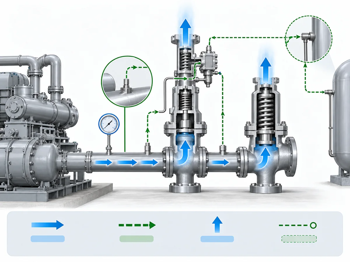
In common internally sensed POSRV architectures, pressure is taken from the main-valve inlet and communicated through the pilot/control circuit. Under suitable inlet conditions, this can represent the protected system well enough for the valve to operate as intended.
But three pressures should not automatically be treated as identical under all installed conditions:
protected-system pressure → pressure at the sensing point → pressure delivered to the pilot
During relieving flow, pressure loss between the protected equipment and the valve inlet can make the local valve-inlet pressure differ from the upstream system pressure. If the pilot senses locally, that difference can become part of the valve’s control behavior.
An engineer reviewing compressor service should therefore identify three things.
Where is pressure picked up?
Is the pilot sensing internally near the main-valve inlet, or is pressure taken from another location?
What happens at that point when relief flow begins?
A location that appears representative before the valve opens may experience a different pressure once significant flow develops.
How does the signal reach the pilot?
A remote sensing connection is part of the valve control system, not simply an instrumentation convenience. Its arrangement has to follow the actual pilot design and supplier requirements.
This does not make integral sensing inherently unsuitable for compressors, nor does it make remote sensing inherently superior.
So the engineering question becomes:
Does the pressure reaching this pilot represent the protected system closely enough under the condition for which the valve is being evaluated?
For the full generic pilot/main-valve operating sequence, see how a pilot-operated safety valve works. That page owns the broader POSRV operating principle, while this article stays focused on compressor-system sensing and dynamic behavior.
Remote Sensing: What It Can Correct—and What It Cannot
Remote sensing is valuable when it corrects a defined pressure-reference problem. It should not be treated as a generic anti-pulsation feature.
What Remote Sensing Can Correct
When inlet pressure loss becomes significant during relief, a pilot sensing directly at the main-valve inlet may see a lower pressure than exists farther upstream in the protected system.
For applicable POSRV architectures, remote sensing moves the pilot pressure reference to another system location. That can prevent the pilot from reacting to the locally depressed valve-inlet pressure and can address cycling or chatter associated with that sensing mechanism.
Emerson’s Pressure Relief Valve Engineering Handbook describes this pressure-reference function for applicable pilot-operated designs. See Emerson’s Pressure Relief Valve Engineering Handbook.
What Remote Sensing Cannot Correct
The main relieving flow still travels through the installed inlet piping.
Changing where the pilot senses pressure does not remove the physical pressure loss in that main flow path. Even when remote sensing lets the pilot see the upstream system pressure correctly, the capacity delivered by the main valve can still be affected by inlet-line losses.
That produces one of the most important distinctions in this article:
Correcting the pilot’s pressure reference is not the same as correcting the installed relief flow path.
Consider a simple screening example. If upstream system pressure remains elevated during relief while local pressure at the valve inlet falls because of the inlet arrangement, moving the pilot’s sensing reference may address the control-signal problem. The same change does not make the inlet restriction disappear.
Remote sensing also introduces supplier-specific design questions. Sensing-line length, fittings, elevation and tubing requirements can matter, but those requirements should come from the actual valve manufacturer rather than being copied from another POSRV family.
Before specifying remote sensing, work through four checks:
- Identify the source of the pressure disturbance.
- Identify what pressure the pilot currently sees.
- Determine whether changing the sensing source addresses that mechanism.
- Separately verify the main-valve inlet and relieving flow path.
A compressor POSRV should not pass installation review simply because its pilot has been given a more representative pressure signal.
Pop-Action vs Modulating Pilot: Match the Response to the Pressure Dynamics
“Pilot operated” is not one opening behavior. Pop-action and modulating pilots can control main-valve lift differently, so pilot architecture belongs in the dynamic-service review.
In a pop- or snap-action architecture, the pilot can command a relatively rapid transition toward the main valve’s relieving condition. A modulating architecture can instead vary main-valve lift with the relief demand in applicable designs.
Baker Hughes’ Consolidated POSRV technical documentation distinguishes pop-action and modulating configurations. See the Consolidated 2900-40 POSRV technical specification.
Those differences matter, but they do not establish a universal compressor winner.
| Review point | Pop-action pilot | Modulating pilot |
|---|---|---|
| Main-valve response | More discrete or rapid transition in applicable designs | Main-valve lift can vary with relief demand |
| Dynamic-service question | Will the actual design remain stable for the defined pressure behavior and inlet arrangement? | Does the modulating response suit the defined pressure behavior and required relief duty? |
| Reseating behavior | Must be checked for the specific pilot/main-valve design | Must also be checked for the specific design |
| Selection evidence | Manufacturer data for the actual pilot and service | Manufacturer data for the actual pilot and service |
A modulating pilot should not be described as an anti-pulsation device. A pop-action pilot should not be rejected merely because the compressor produces dynamic pressure.
Ask the supplier a more concrete question:
How does this exact pilot/main-valve architecture behave as pressure approaches the set condition, changes while relieving, and falls toward reseating?
That keeps the comparison tied to the actual compressor duty instead of turning it into a generic feature ranking.
Blowdown and Reseating Must Fit the Compressor Operating Envelope
In this article, blowdown means the pressure difference between the valve’s set pressure and its reseating pressure. Baker Hughes uses that definition in its Consolidated POSRV terminology. See the Consolidated 2900-40 POSRV manual.
This is different from compressor-package “blowdown” or system depressuring.
That terminology boundary matters because the useful engineering question is not:
“What blowdown percentage does this valve have?”
It is:
How far must pressure fall before this valve reseats, and is that closing behavior compatible with the compressor system’s normal and recovering pressure?
Think of the sequence as an operating envelope:
normal operation → pressure rise → opening/set condition → relief → pressure falls → reseating
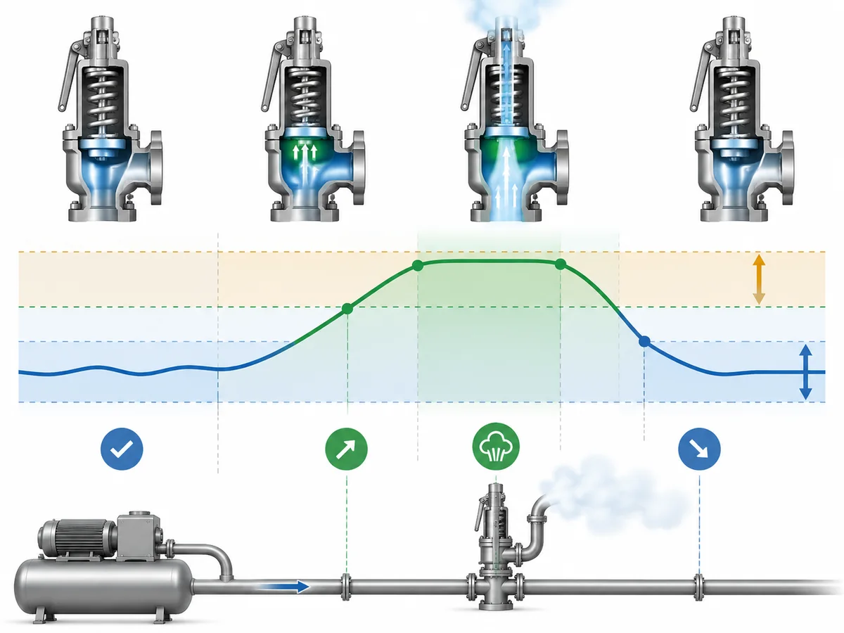
Pop-action and modulating pilots can have different opening and closing characteristics. Product literature also shows that blowdown behavior is configuration-specific rather than a single universal compressor value.
For example, Baker Hughes lists blowdown as a defined POSRV parameter for particular product families. See the Consolidated 2900/2900 TM technical specification. Those product-specific values should not be converted into an industry-wide compressor rule.
Review these four items together:
- normal and maximum expected operating pressure;
- relevant pulsation or transient behavior;
- the valve set-pressure basis;
- the valve’s actual reseating behavior.
Baker Hughes’ Consolidated 2900-40 documentation notes that pump and compressor discharge lines may require additional differential between operating and set pressure because reciprocating-piston pressure pulsations can be present. That supports checking the actual pressure envelope rather than relying only on an average operating pressure.
This does not justify a single universal margin or blowdown percentage. The acceptable relationship depends on the actual valve architecture, service, governing project basis and manufacturer evidence.
If those relationships are not defined well enough to know whether the valve can close and remain closed as intended, the candidate should remain under review even if its nominal pressure rating and capacity appear suitable.
Compressor POSRV RFQ: Verify the Installed System, Not Just the Valve
A useful compressor POSRV RFQ needs more than medium, temperature, pressure and connection size. It needs enough information to define the relief duty, understand the pilot’s pressure signal, and review the installed inlet and discharge system.
ISO 4126-4 is useful for understanding the product category, but ISO describes it as a product standard and states that it does not provide application guidance for pilot-operated safety valves. See ISO 4126-4.
API’s standards structure likewise separates pressure-relief responsibilities across sizing/selection, installation, and the wider pressure-relieving/depressuring system context. See API’s current standards plan.
For a compressor POSRV review, organize the inputs into six groups.
Relief-Duty Basis
Confirm:
- the equipment or pressure boundary being protected;
- the credible overpressure scenario;
- required relieving capacity;
- applicable project or code basis.
The valve type should not be used to invent the relief case.
Process Conditions
Provide, as applicable:
- fluid and phase/state;
- normal operating pressure;
- set-pressure basis;
- operating temperature;
- relieving temperature;
- required capacity and relevant sizing data.
Compressor Pressure Dynamics
If pulsation, spikes or unstable pressure are part of the concern, “pulsating service” is not enough information.
Useful review inputs can include:
- compressor type;
- what pressure variation is expected or observed;
- where that pressure was observed;
- whether it exists during normal compressor operation or appears mainly when the relief valve flows;
- a pressure trace or pulsation study when one is available.
These are engineering-review inputs, not a claim that every project is required by a particular standard to provide the same dataset.
Pilot and Sensing Arrangement
Identify:
- pop-action or modulating pilot, where known;
- internal/local or remote sensing;
- sensing location;
- remote sensing-line information where applicable;
- any filter, snubber or other accessory being proposed.
If an accessory is intended to solve a dynamic-pressure problem, state which mechanism it is intended to address.
Installed Inlet and Discharge System
Provide enough information to review:
- valve inlet arrangement and known pressure-loss concerns;
- discharge destination;
- built-up or superimposed backpressure where relevant;
- downstream conditions that could affect the selected valve architecture.
A remote sensing line should never be used as evidence that an unresolved main-valve inlet problem no longer matters.
Blowdown and Operating Envelope
Confirm:
- normal operating-pressure range;
- relevant dynamic pressure behavior;
- required or acceptable reseating basis;
- how system pressure is expected to recover after the relief event.
That lets supplier engineering compare the valve’s actual reseating behavior with the compressor duty.
Candidate-Screening Decision
The terms below are this article’s engineering screening framework, not regulatory classifications.
PROCEED TO ENGINEERING / RFQ REVIEW
The relief duty is defined, sensing arrangement is understood, and the relevant pressure dynamics and installed-system information are sufficient for supplier evaluation.
HOLD
The pressure disturbance is still undefined; the sensing point is unknown; remote sensing or another accessory is proposed without a clear mechanism; or inlet, backpressure or reseating conditions remain unresolved.
REJECT CANDIDATE
Use only when a known, evidence-supported mismatch has already been established. Missing data alone is a reason to hold the review, not to manufacture a rejection rule.
For readers still defining the wider compressor relief duty, see ZOBAI’s compressor safety-valve application guide.
For readers who have not yet selected between spring-loaded and pilot-operated architectures, see the spring-loaded vs pilot-operated safety-valve comparison.
If the duty has already been defined and you need the relevant product-family context, see ZOBAI’s pilot-operated safety valves. Product-family information does not replace application-specific engineering review.
For a compressor POSRV RFQ, the next useful step is to provide the defined relief duty together with the pressure-dynamic, sensing, inlet/discharge and reseating information needed to review the actual candidate. A final model, capacity, material, certification and code-compliance decision still depends on the project data and the responsible engineering basis.