Learn how to evaluate pilot-operated safety valve seat tightness near set pressure, interpret API 527, and verify product-specific leakage limits.

A pilot-operated safety valve can, in some designs, maintain tight shutoff while operating pressure is relatively close to set pressure. That does not mean every pilot-operated valve has the same allowable operating margin, nor does an API 527 seat-tightness result by itself define how close an installed system should normally operate to set pressure.
Three questions need to be separated:
- Does the valve meet a defined seat-tightness test?
- Is the specific valve design intended to operate at the actual pressure-to-set-pressure relationship?
- Does observed leakage in service indicate a valve problem, a pilot/control-path issue, another sealing path, or an observation that still needs to be localized?
That distinction matters more than finding a single 95%, 97% or 98% number.
For an engineering review, start with the actual set pressure, normal operating pressure, valve and pilot configuration, observed leakage location, and applicable test or acceptance basis.
What Does “Seat Tightness Near Set Pressure” Actually Mean?
“Seat tightness near set pressure” is not one engineering condition.
Set pressure identifies the pressure setting associated with the valve’s specified opening or actuation behavior. Normal operating pressure is the process pressure during service. A seat-tightness test pressure is the controlled pressure used when leakage is evaluated under a specified test procedure.
Those pressures may be related, but they answer different questions.
A successful bench tightness test does not, by itself, establish the maximum normal operating pressure of the installed system. Likewise, a manufacturer statement that a particular pilot-operated valve can operate close to set pressure does not automatically define the acceptance criteria for an API 527 test.
Seat-tightness testing and installed operation are different questions
A seat-tightness test asks:
Does leakage satisfy the applicable acceptance basis under the defined test conditions?
An installed-operation review asks:
Is the actual operating condition within the documented application and operating basis of this valve configuration?
The second question requires more than a leakage test report. The engineer also needs the valve design, operating pressure, set pressure, pilot configuration and relevant system conditions.
First identify which leakage path is being discussed
“Valve leakage” is too broad for a useful diagnosis.
| Observation | What it may indicate | What it does not prove by itself |
|---|---|---|
| Flow observed at the main outlet | Internal flow through a main-valve sealing path | That the main seat alone is damaged |
| Flow or leakage at a pilot vent/control path | Pilot operation or pilot/control leakage, depending on the design and state | Main-valve seat leakage |
| Leakage at tubing, fittings or external joints | External connection or sealing problem | Internal main-seat failure |
| Leak location cannot be identified | Diagnostic information is incomplete | Any specific valve defect |
This distinction should be made before discussing repair, rejection or operating margin.
Why Can a Pilot-Operated Valve Remain Tight as Pressure Approaches Set Pressure?
The answer lies in the closing-force arrangement of the specific pilot-operated design.
In a common piston-type arrangement, system pressure is routed to a dome or control chamber above the main piston. When pressure acts over a larger effective closing area than the area producing the opening force at the seat, the resulting force balance can hold the main valve closed.
For this type of architecture, increasing inlet pressure can therefore continue to contribute to net seating force while the pilot maintains the required dome pressure.
LESER, for example, explains its pilot-operated design using this differential-area principle and links the increasing closing force to operation close to set pressure. The mechanism is useful for understanding why near-set tightness can be possible, but its exact pressure limits remain product-specific. LESER High Efficiency POSV technical information.
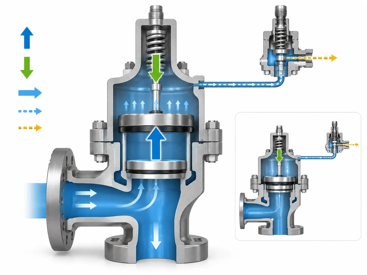
For more detail on the full operating sequence rather than only the seat-tightness mechanism, see how a pilot-operated safety valve works.
Pilot action and main-valve opening are not always the same event
Pilot-operated designs differ in how pressure is controlled as the system approaches set pressure.
A modulating pilot may begin changing the control pressure before the main valve reaches a fully relieving state. Other pilot arrangements can follow different sequences.
For that reason, pilot activity, pilot vent flow and main-valve seat leakage should not be treated as synonyms.
Use the documented operating behavior of the actual pilot and main-valve configuration, not a generic assumption about all pilot-operated valves.
Is 95% or 98% of Set Pressure a Universal Seat-Tightness Rule?
No. A 95%, 97% or 98% figure is not a universal pilot-operated safety-valve rule.
The spread across original manufacturer literature shows why. Emerson’s Anderson Greenwood Series 200 states total valve tightness to at least 95% of set pressure for that series; LESER lists operating pressures up to 97% of set pressure for its High Efficiency pilot-operated product group; and Baker Hughes states main-valve and pilot-seat tightness up to 98% of set pressure for its Consolidated pilot-operated valves. Each figure belongs to the product and claim in which it is published—not to the entire POSRV category.
Sources: Emerson Anderson Greenwood Series 200, LESER High Efficiency POSV, and Baker Hughes Consolidated POSRV.
Four questions to ask before using any percentage
- Who owns the number? Is it the valve manufacturer, a project specification, a test procedure or another source?
- What does the percentage describe? Normal operating pressure, seat-tightness performance, test pressure, pilot cracking behavior and blowdown are different parameters.
- Which valve configuration does it apply to? Confirm the series, pilot type, seat arrangement and relevant options.
- Under what condition does it apply? A bench test, product performance statement and installed operating recommendation are not automatically equivalent.
This prevents a common sourcing mistake: finding the highest percentage published by one supplier and using it to evaluate a different valve.
Do not turn a product capability into an industry rule
A statement such as “tight to 98% of set pressure” may be meaningful when it belongs to the exact valve family being evaluated.
It becomes technically unreliable when rewritten as:
All pilot-operated safety valves can operate at 98% of set pressure without leakage.
The evidence does not support that generalization.
For ZOBAI’s ZBXD series, the supplied product catalog identifies a pilot-operated pressure-relief-valve family and references API 527 for tightness, but it does not provide a verified 95%, 97% or 98% near-set operating claim. That boundary should remain explicit.
API 527 Seat-Tightness Testing vs Actual Operation Near Set Pressure
API Standard 527 is specifically titled Seat Tightness of Pressure Relief Valves. API’s standards catalog lists Standard 527 as the fifth edition issued in 2020. API Standards Plan.
The current API 527 scope listing describes methods for determining seat tightness of metal- and soft-seated pressure-relief valves and explicitly includes pilot-operated designs. API STD 527 current scope listing.
That makes API 527 directly relevant to this article—but only for the job it actually performs.
What API 527 evidence can establish
An applicable API 527 test can provide evidence that the valve met the relevant seat-tightness acceptance basis under the prescribed test conditions.
For procurement and QA, that is useful because it gives the buyer and supplier a defined basis for discussing leakage acceptance.
For a deeper treatment of the test itself, see ZOBAI’s API 527 seat-tightness test guide.
What it does not establish by itself
An API 527 result does not, by itself, establish:
- the maximum normal operating pressure for the installed process;
- a universal 95%, 97% or 98% operating limit;
- guaranteed zero field leakage under every service condition;
- that pilot, sensing, external seals or downstream conditions cannot contribute to a leakage problem;
- that every pilot-operated valve referencing API 527 has the same operating margin.
ISO 4126-4 reinforces the need to separate product requirements from application decisions. ISO describes Part 4 as a product standard for pilot-operated safety valves and states that it is not an application standard. ISO 4126-4.
Avoid turning a test reference into a certification claim
If a catalog or test document states that tightness conforms to, or is tested using, API 527, retain that exact scope.
Do not silently rewrite it as:
The valve is API 527 certified.
A test-standard reference, product capability statement, code stamp and project approval are different forms of evidence.
If Leakage Appears Near Set Pressure, Identify the Leak Path Before Diagnosing the Valve
Leakage near set pressure is a symptom, not a root-cause diagnosis.
The first useful question is:
Where is leakage actually being observed, and what was the pressure and operating state when it appeared?
Only after that observation is clear should the engineer begin narrowing the possible cause.
Start with the observation, not the repair
| What you observe | What to verify next | Why |
|---|---|---|
| Leakage at the main outlet | Actual pressure, set pressure, applicable tightness basis and valve condition | Outlet flow alone does not identify the exact internal sealing path |
| Flow at a pilot vent/control path | Pilot type, operating state and documented pilot behavior | Pilot activity does not automatically prove main-seat leakage |
| Leakage at an external fitting or tubing joint | Connection and external sealing condition | It is a different path from main-seat leakage |
| Leakage appears only close to set pressure | Actual operating/set-pressure relationship and product-specific operating basis | The valve’s documented operating margin may matter |
| Leakage appears after a lift or maintenance event | Event history and applicable OEM inspection basis | The relevant checks may change after a relief or service event |
| Leak path remains unknown | Improve the observation or escalate the review | Diagnosis without knowing the path is speculation |
Then separate system conditions from valve conditions
Possible system or operating variables include:
- actual pressure relative to set pressure;
- steady versus transient pressure;
- downstream or back pressure where relevant;
- sensing arrangement;
- dirty or contaminated service conditions.
Possible valve/configuration variables include:
- pilot type;
- main-seat or seal condition;
- pilot/control-path condition;
- filter or sensing components where fitted;
- relevant internal seals.
These are investigation categories, not automatic root causes.
A high operating pressure does not prove the valve is defective. Contaminated service does not prove contamination caused the leakage. A pilot vent does not prove the main seat is leaking.
Stop before generic troubleshooting becomes unsafe adjustment advice
A general article should not instruct a reader to change:
- set pressure;
- pilot adjustment;
- blowdown;
- internal spring or seal settings;
- sensing configuration.
Those actions require the correct valve procedure and qualified review because they can affect the protection function.
If the observed behavior conflicts with the applicable OEM or test basis, or the leak path cannot be established safely, move to product-specific engineering or service review rather than continuing by assumption.
What Should Be Verified Before Accepting, Rejecting or Escalating the Valve?
A technically useful supplier inquiry should allow the engineer to reconstruct the condition in which the leakage was observed.
Sending only:
Pilot safety valve leaks near set pressure—please advise.
leaves too many variables unresolved.
1. Pressure condition
Provide:
- specified set pressure;
- actual normal operating pressure;
- pressure at which leakage appears;
- whether pressure is steady, rising, falling or cycling;
- outlet/back pressure where relevant.
The pressure ratio only becomes useful when compared against documentation for the actual valve.
2. Exact valve and pilot configuration
Identify:
- manufacturer;
- valve series/model;
- pilot type;
- pop-action or modulating arrangement where applicable;
- seat/seal construction if relevant;
- pressure-sensing arrangement;
- relevant options or accessories.
ZOBAI’s own ZBXD catalog demonstrates why configuration should be captured: the series includes multiple pilot and configuration options rather than one universal arrangement. That is a product-configuration fact, not evidence for an unlisted near-set tightness percentage.
If the task has moved from diagnosis to product selection, see ZOBAI pilot-operated safety valves.
3. Service and test context
Clarify whether the observation occurred during:
- a bench seat-tightness test;
- field verification;
- normal plant operation;
- startup or another transient;
- a condition after the valve lifted.
Include the medium, relevant phase/state, temperature and contamination information where those variables matter to the applicable valve.
4. Describe the leakage itself
Record:
- where it was observed;
- how it was observed;
- whether it is continuous or intermittent;
- the pressure at which it begins or stops, if known.
“Leakage at the main outlet at a known operating pressure” is much more actionable than “the valve leaks.”
5. Identify the acceptance basis
Provide the applicable:
- project tightness requirement;
- API 527 basis where used;
- OEM test procedure;
- purchaser specification;
- available supplier test report.
Without an acceptance basis, an observation cannot be converted reliably into “pass” or “fail” merely from a generic online percentage.
A practical engineering screening decision
Continue the evaluation when the valve identity, pressure state, leakage path and applicable acceptance basis are known.
Hold the judgment when a critical input is still unknown.
Escalate for product-specific review when the observed behavior conflicts with documented valve or test requirements, or when diagnosis would require OEM-specific inspection or adjustment.
These are article-level engineering screening labels, not API, ISO or regulatory classifications.