Learn how to read safety valve nameplate data and certified capacity records, match valve and documentation, and spot gaps before engineering review.

A safety valve nameplate and a certified-capacity record should be read together, not as two unrelated pieces of information. The nameplate helps establish which valve and configuration you are looking at; the capacity record tells you what capacity evidence applies to a defined pressure-relief-device design and rating basis.
The common mistake is to find a familiar model, set pressure or capacity number and begin comparing values immediately. A technically correct number can still be the wrong evidence if it belongs to another valve type, configuration, certified medium, set-pressure range or rating condition.
A better review follows an evidence chain: physical valve → nameplate and traceability → certified design/configuration → certified-capacity record → rating conditions → comparison with the actual required relieving load.
“Certified-capacity record” is deliberately broader than “capacity curve.” National Board NB-18 recognizes several ways of establishing a certified capacity value, including direct capacity, flow-factor/slope and coefficient-based methods; the result may therefore appear as a value, table, listing, coefficient or curve rather than one universal graph. National Board NB-18 explanatory material.
This guide focuses on how to interpret and reconcile that evidence. It does not replace the relief-load calculation, full valve sizing process or installed-system review. API 520 Part I is the sizing-and-selection reference for pressure-relieving devices in refinery service; the required relief duty still comes from the protected system and the governing overpressure scenario, not from the valve nameplate. API 520 Part I.
Match the Valve to the Document Before Reading the Capacity
Before reading the capacity, establish that the capacity information actually belongs to the valve being reviewed.
Start with the identifiers available on the physical valve, nameplate and supporting documents. Depending on the manufacturer and certification route, useful matching information may include the manufacturer, model or design type, inlet and outlet size, set pressure, serial or tag information, certification designator and capacity-related configuration data.
These identifiers do not all perform the same job.
For National Board records, the capacity certification number is assigned to the certified valve type. NB-18 separately lists the manufacturer’s commercial design-type name, the applicable construction-code designator, certification category, size information, flow-area/orifice data where applicable, set-pressure ranges and certified media. A manufacturer serial number, by contrast, is used to trace an individual physical valve and should not be treated as the capacity-certification identifier. National Board NB-18 Pressure Relief Device Certification.
During replacement or document review, a model family can identify the general design, but a capacity-relevant configuration still needs to be checked where applicable. National Board NB-500 requires design review and new testing when an existing pressure-relief-device design is modified in ways that affect the flow path, lift or performance characteristics. National Board NB-500.
- Identify the physical valve. Record the readable nameplate, manufacturer, model/style, size, set pressure, serial/tag and applicable marks.
- Match the design. Confirm that the certification or manufacturer record is for the same design type, not merely the same brand or product family.
- Match capacity-relevant geometry/configuration. Check size, flow area, orifice/lift information or other certified configuration identifiers where the record provides them.
- Match the certification context. Confirm the applicable ASME/National Board designator or other certification basis rather than assuming every marking carries the same scope.
- Only then read the capacity value. Capacity comparison is the last step in identity matching, not the first.
The objective is simple: do not perform an accurate capacity calculation or comparison against documentation for the wrong valve.
Read the Nameplate by What Each Field Proves
There is no benefit in memorizing one manufacturer’s nameplate layout and assuming every safety valve will look the same. Read the safety valve nameplate by the evidence function of the information instead.
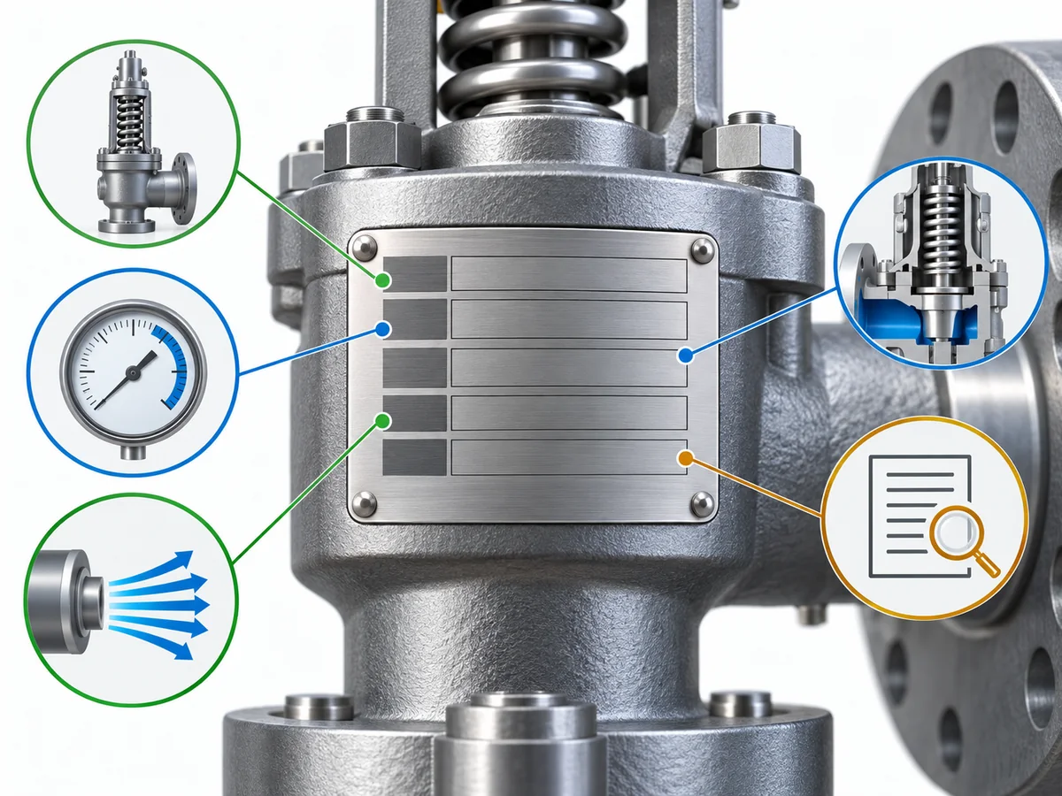
| Evidence function | Information you may encounter | What it helps establish | What it does not establish by itself |
|---|---|---|---|
| Identity and traceability | Manufacturer, model/design, serial or tag information where provided | Which physical valve or design is being reviewed | Certified capacity or application suitability |
| Pressure information | Set pressure, pressure unit, overpressure/test-adjustment fields or back-pressure data where applicable | Pressure-related identity and rating context | The protected system’s required relieving load or the complete certified-capacity basis |
| Flow and capacity information | Certified capacity, flow area, flow coefficient, lift or orifice-related information where applicable | Capacity-related characteristics of the certified design | That the valve can satisfy a particular relief case without a separate load comparison |
| Certification information | Applicable code designator, ASME Certification Mark or National Board mark where present | The certification framework that may apply to the device | Automatic acceptance for every jurisdiction, owner or process service |
| Configuration or service context | Temperature or manufacturer-specific configuration information where present | Additional evidence for matching the valve to documentation | Complete process or installed-system suitability |
This “field → evidence function → limit” approach is more useful than a field glossary because a valid field can still be asked to prove something it was never intended to prove.
A current Emerson Crosby sample nameplate illustrates why the fields must be kept separate. The plate identifies connection size, certified flow coefficient, certified flow area, ASME capacity, overpressure, set pressure, cold differential test pressure, back-pressure information, temperature and other traceability data as distinct fields; Emerson also cautions that markings vary with the certification required. Emerson Crosby EM Series sample nameplate.
That separation is important. Set pressure tells you when the valve is adjusted to display the specified opening characteristic; certified capacity tells you the tested/rated relieving-performance evidence for the certified design and basis. Neither one is the protected system’s required relieving load.
Likewise, an inlet or outlet connection size helps identify the piping interface. It is not a substitute for relieving-capacity evidence. For the deeper distinction between nominal connection size, internal flow geometry and capacity, see Certified Relieving Capacity vs Connection Size.
For National Board-marked devices, the program is narrower and more specific: the NB-18 administrative requirements state that when the NB mark is applied, the relieving capacity or flow resistance marked on the device must be the value certified by the National Board as computed under the applicable construction code. National Board pressure-relief-device certification administrative requirements.
That is strong capacity evidence within that certification framework. It still does not turn every other nameplate field into a universal requirement, and it does not establish the complete suitability of the valve for a specific process system.
Read a Certified Capacity Curve or Table from Its Basis, Not Just the Number
A certified capacity number should never be separated from the basis under which it was established.
National Board NB-18 illustrates this clearly. Its certification records can associate a quantitative rating value and unit with a test medium, certified media, inlet/outlet size, flow area, orifice diameter, minimum lift, valid set-pressure ranges and code designators. NB-18 also recognizes different methods for establishing certified values, including direct flow-capacity, flow-factor/slope and coefficient-of-discharge methods. NB-18 listing explanation.
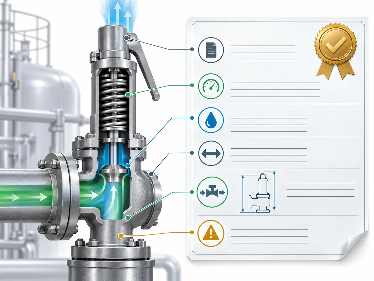
- Identify what the number represents. Determine whether the document gives a direct certified flow capacity, a slope/flow factor, a coefficient or another rating value. Two numbers called “capacity” are not automatically comparable if they were established by different methods.
- Check the unit and reference basis. A capacity value without its unit and basis is not ready for comparison. Mass flow, standard volumetric flow and liquid volumetric flow are different quantities. Do not convert them casually or compare unlike units.
- Separate test medium from certified medium. NB-18 explicitly distinguishes the medium used during initial testing from the medium or media for which the device is certified for service. Seeing “air,” “steam” or “water” in a test field does not by itself tell you the complete certified-service scope.
- Check the size and flow geometry associated with the record. Connection size, flow area, orifice diameter and minimum lift are independent data fields in NB-18. A matching flange size alone is therefore weak evidence of a matching certified capacity basis.
- Confirm that the set pressure is within the applicable record. NB-18 associates minimum and maximum set pressures with the applicable size, code designator and certified medium. The stamped set pressure is a matching input; it is not the capacity itself.
- Read the limitations before using the value. NB-18 states that its listed rating values were established under atmospheric-discharge conditions and cautions that calculated capacities may not remain applicable when discharge back pressure exists. It also states that capacities are certified only for the conditions under which they were obtained.
That NB-18 limitation should not be generalized into a claim that every capacity document from every certification system has exactly the same boundary. It demonstrates the broader engineering principle: a certified capacity is condition-bound evidence, not a universal flow number.
Only after the valve identity, rating method, unit, certified medium, applicable size/configuration, pressure range and relevant limitations align should the value be compared with the engineering requirement.
If the task is still to determine the required relieving capacity, relieving conditions or required orifice, use the separate Safety Valve Sizing and Certified Relieving Capacity Guide. API 520 Part I likewise treats sizing and selection as an engineering task separate from merely reading a certified rating. API 520 Part I sizing and selection scope.
Cross-Check the Capacity Record Against the Physical Valve
Understanding the nameplate and understanding the capacity record are not enough if you never reconnect them.
The next task is to verify that the physical valve and the capacity evidence describe the same capacity-relevant design.
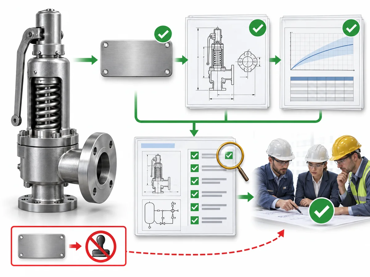
| Cross-check | Physical valve / nameplate side | Certified-capacity side | Question to answer |
|---|---|---|---|
| Manufacturer | Manufacturer identification | Certified manufacturer/assembler information | Are you reviewing evidence from the correct source? |
| Design | Model, style or other design identity | Certified design type | Does the record belong to this design? |
| Size | Marked inlet/outlet size where available | Listed applicable size or range | Is the certified record for this size? |
| Flow geometry | Orifice, flow area, lift or related data where available | Certified flow area/orifice/lift data where listed | Does the capacity evidence describe the same flow configuration? |
| Pressure | Stamped set pressure | Applicable certified set-pressure range | Does this valve fall within the rating range? |
| Medium | Process service may be established outside the nameplate | Certified medium | Is the rating basis relevant to the service being evaluated? |
| Certification | Mark or designator where applicable | Certification listing and designator | Does the certification context align? |
Not every valve nameplate will contain every field in this table. The purpose is not to demand an identical set of markings from every manufacturer. The purpose is to obtain enough independent matching information to establish that the capacity record applies to the design actually in front of you.
Capacity certification is tied to pressure-relief-device designs. NB-500 requires design review and initial testing to establish rated capacity or flow resistance, while modifications that affect performance require review. National Board NB-501 describes the broader design-certification program and basic requirements. National Board NB-501.
In practice, keep the evidence chain traceable: physical valve → identifying information → certified design/configuration → capacity record → rating conditions → required load comparison.
Do not collapse that chain into “the model looks right.”
There is also an important historical-data limitation. The current NB-18 database does not list organizations that no longer hold certification or device-design certifications no longer in production. For an older installed valve, no current NB-18 result is not proof that the valve type was never historically certified. National Board guidance directs users to contact its Pressure Relief Department for historical information. NB-18 historical-listing limitation.
Know What Certification Evidence Proves—and What It Does Not
Certification evidence becomes most useful when its scope is kept intact.
ASME BPVC Section XIII currently provides rules for overpressure protection and covers pressure-relief-device design, materials, inspection, assembly, testing, marking, capacity/flow-resistance certification, authorization to use the ASME Certification Mark and installation. ASME BPVC Section XIII.
ASME’s 2025 conformity-assessment requirements list UV — Pressure Vessel Pressure Relief Valve certification under BPVC Section XIII and identify a capacity-certification test as part of that certification program. ASME’s required code books list also identifies the standards associated with UV certification. The National Board acts as an ASME-designated organization for pressure-relief-device certification activities and maintains the NB capacity-certification program. ASME CA-1 conformity-assessment requirements National Board Pressure Relief Laboratory.
| Certification evidence can support | Certification evidence does not establish by itself |
|---|---|
| A defined pressure-relief-device design/type has been certified within the applicable program | The protected system’s required relieving load |
| Capacity or flow-resistance evidence has been established under that certification framework | That a specific project sizing calculation is correct |
| The applicable certification/designator context | That the installed inlet and outlet piping are acceptable |
| Authorized marking within the defined scope | Material/process compatibility with every possible service |
| A traceable basis for reviewing the device rating | Acceptance by every owner, jurisdiction or project specification |
The National Board itself cautions against interpreting NB-18 too broadly. Its foreword states that listed capacity rating values come from testing samples of the relevant device type, that capacity is certified only for the conditions under which it was obtained, and that installation, operating conditions and manufacturer recommendations still need to be considered when selecting a pressure-relief device for service.
The practical boundary is not certification mark → valve automatically approved for the project. It is certification evidence → one verified part of the project’s overall technical evidence.
The same distinction works in the other direction. Missing or inconsistent documentation does not automatically prove that a valve is physically defective, unsafe or noncompliant. It means the evidence available to the reviewer is insufficient for the conclusion being attempted.
For a broader explanation of certification and standards roles, see the Safety Valve Standards Guide.
Stop the Review When the Evidence Does Not Match
A good nameplate review does not have to end with “approved” or “rejected.” Often the correct result is simply: the current evidence is not sufficient yet.
Mismatches That Require Further Verification
| What you find | Why it matters | Appropriate next action |
|---|---|---|
| Physical valve identity cannot be established | You cannot reliably connect the capacity record to the device | Recover readable nameplate/tag and manufacturer identification |
| Design or capacity-relevant configuration differs | The certified rating may belong to a different design | Obtain the exact configuration and corresponding capacity documentation |
| Test medium is being treated as if it automatically defines the certified service medium | NB-18 distinguishes initial test medium from certified media | Verify the certified-media entry for the applicable record |
| Set pressure is outside or cannot be tied to the applicable range | The record may not cover the valve being reviewed | Obtain the applicable certification/rating record for that set-pressure basis |
| Connection size matches but flow/orifice evidence does not | Mechanical fit is not capacity equivalence | Confirm exact certified flow geometry and supported capacity |
| NB-18 atmospheric-discharge capacity is being applied where back pressure matters | The listed rating may not apply directly | Obtain the applicable manufacturer or project engineering basis |
| Certified capacity is lower than the actual required relieving load | The certificate can be valid while the candidate remains undersized for the relief case | Return to sizing/selection; do not reinterpret the certified rating |
| Nameplate capacity conflicts with the certification record | At least one part of the evidence chain is unresolved | Resolve the discrepancy before choosing either value |
| Mark or designator scope is unclear | The meaning of the certification cannot be established | Confirm the applicable certification scope |
| Older valve is absent from today’s NB-18 database | Current search results do not necessarily show historical certification | Request historical verification instead of assuming non-certification |
The National Board’s NB-18 limitations support this cautious approach: its listed capacities are condition-specific, the database has current-versus-historical limitations, and installed operating conditions still have to be considered.
Use verify before relying here—not automatically “unsafe,” “noncompliant” or “must be replaced.”
What to Request Before the Review Continues
Do not answer an evidence gap with the vague request “please send the certificate.” Ask for the document that closes the actual gap.
- Identity gap: request a readable nameplate/tag image plus manufacturer, model/style and serial/tag information.
- Certification gap: request the applicable NB-18/ASME or manufacturer certification record that identifies the design type and scope.
- Capacity-basis gap: request the capacity listing/table/curve with its unit, method, certified medium, applicable size/configuration and set-pressure range.
- Required-load gap: request the governing relief-case calculation and relieving conditions; a certificate cannot supply the protected system’s required load.
- Installed-condition gap: if back pressure or another installed condition differs from the certification basis, request the manufacturer or project engineering basis that addresses that condition.
- Historical-record gap: for an older design absent from current NB-18, request historical verification rather than treating current database absence as proof of non-certification.
Continue review: the valve identity, certified design/configuration, capacity evidence, rating conditions and required-load comparison align.
Verify further: an important relationship is unresolved but can be closed with additional evidence.
Do not rely on the capacity comparison yet: known information conflicts or the rating basis does not match the condition being evaluated.
These are practical document-review states used in this guide, not ASME, API or National Board regulatory classifications.
For the broader purchasing and document-control process, continue with the Safety Valve Procurement Checklist.
The final decision should still be made against the applicable project code, equipment design basis, service conditions and authorized engineering review—not from a nameplate field in isolation.
Frequently Asked Questions About Certified Capacity Curves and Nameplates
Is set pressure the same thing as certified relieving capacity?
No. Set pressure identifies the pressure basis for the valve’s specified opening characteristic. Certified relieving capacity is performance evidence for a certified design under its stated rating basis. Neither value tells you the protected system’s required relieving load.
What is the difference between the test medium and the certified medium in NB-18?
The test medium is the fluid used during the initial certification testing. The certified medium is the medium for which the device’s certified rating is listed for service. NB-18 treats these as separate fields, so service applicability should be read from the certification record rather than inferred from the laboratory test fluid alone.
Can I size a safety valve from the capacity stamped on the nameplate?
No. The required relieving load must first be determined from the protected system and governing overpressure scenario. The applicable certified or rated valve capacity is then compared with that requirement under the relevant relieving conditions.
Does an NB or ASME mark prove that the valve is suitable for my installation?
No. Certification supports a defined device design and certification scope. It does not by itself establish the project’s relief load, installed piping acceptability, material compatibility, back-pressure suitability, owner acceptance or jurisdictional acceptance.
Can an NB-18 capacity value be used unchanged when the valve has back pressure?
Not automatically. NB-18 states that its listed rating values were established under atmospheric-discharge conditions and cautions that calculated capacities may not remain valid when discharge back pressure exists. Use the applicable manufacturer, code and project engineering basis for the installed condition.
What if an older valve does not appear in the current NB-18 database?
Do not conclude from current database absence alone that the design was never certified. NB-18 states that organizations no longer holding certification and device designs no longer in production are not listed in the current database; historical information may require direct National Board verification.