Compare balanced bellows and piston balanced safety valves by back-pressure behavior, venting, isolation, failure modes, service limits, and RFQ checks.

Balanced bellows and piston balanced safety valves address the same broad problem: reducing the influence of outlet back pressure on a direct spring-loaded valve. They do it with different pressure boundaries and balancing components.
A balanced bellows valve uses the effective area of a bellows as part of the balancing arrangement. A piston balanced valve uses an effective piston area and its associated sealing and venting arrangement. That difference can affect process isolation, bonnet vent behavior, material compatibility, failure response and maintenance.
There is no universal winner. The better candidate depends on the actual back-pressure condition, service medium, required isolation, temperature, venting constraints and the operating envelope supported by the specific valve manufacturer.
One terminology point should be settled first: a standalone piston balanced valve is not the same thing as a bellows-balanced valve fitted with an auxiliary balancing piston. Spirax Sarco’s safety-valve guidance distinguishes piston-type and bellows-type balanced safety valves while also describing auxiliary pistons used in some bellows designs.
Balanced Bellows vs Piston Balanced: What Are You Actually Comparing?
There are three constructions that can easily be confused.
A balanced bellows valve uses a bellows as the primary balancing element.
Its effective area participates in offsetting the force that outlet pressure would otherwise
apply to the moving assembly.
A standalone piston balanced valve uses a piston as the primary balancing
element. The piston area and pressure above it are arranged so that the relevant back-pressure
forces oppose each other rather than creating the same unbalanced force found in a conventional
spring-loaded valve.
The third construction is a balanced bellows valve with an auxiliary balancing piston.
Here the piston is not automatically the normal primary balancing mechanism. Some designs use
it as backup if the bellows fails.
That distinction matters when reading a drawing or preparing an RFQ. Seeing a piston inside
a valve does not by itself prove that the valve is a standalone piston-balanced design.
A piston balanced spring-loaded valve should also not be confused with a
piston-type pilot-operated pressure relief valve. In a pilot-operated design,
pilot pressure controls the main valve; that is a different operating architecture.
For the broader definition of this valve class, see
what a back-pressure balanced safety valve means
.
How Do Bellows and Piston Designs Balance Back Pressure Differently?
Back pressure can change the forces acting on a spring-loaded pressure relief valve.
A balanced construction changes that force relationship rather than simply increasing spring force.
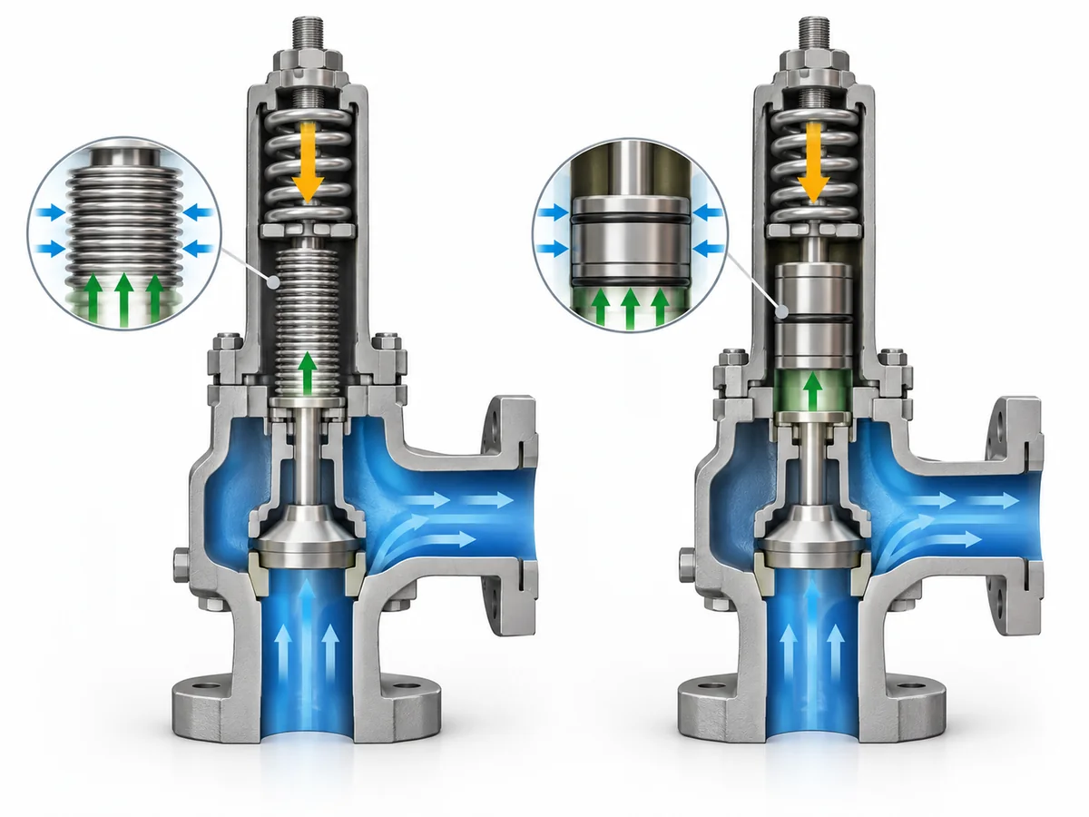
In a piston balanced design, the effective area on the piston is arranged
relative to the nozzle or seat area so that opposing back-pressure forces can offset one another.
The pressure above the piston must also have the intended reference, which makes the bonnet
and vent arrangement part of the balancing system.
A balanced bellows design reaches the same broad objective through the effective
area of the bellows. The bellows prevents outlet pressure from producing the same unbalanced
force over the corresponding part of the disc assembly.
The common principle is pressure-area balancing; the physical component that creates the
balancing area is different.
The word balanced does not mean the valve can tolerate unlimited back pressure,
that discharge capacity can never change, or that outlet piping can be ignored. Real designs
still have manufacturer-specific operating envelopes and may require capacity correction under
particular back-pressure conditions.
Two back-pressure terms should remain separate.
Superimposed back pressure exists at the outlet independently of the current
relief flow. Built-up back pressure develops as relief flow creates pressure
in the downstream system.
The engineering question is not simply whether the valve is “balanced.” It is whether the
selected design remains suitable across the actual back-pressure conditions expected in the
installed system.
For the wider system effect, see
how back pressure affects a spring-loaded safety valve
.
Where Do the Pressure Boundary, Venting and Process Isolation Differ?
Back-pressure compensation is only one part of the comparison. The fluid boundary around the
balancing element can be just as important.
A balanced bellows can provide an additional physical barrier between the outlet/process region
and upper components such as the spindle guide or spring. This isolation function is separate
from the bellows’ role in balancing back-pressure forces.
A piston balanced design establishes the boundary differently. Some designs use seals around
the piston or guide, and the chamber above the piston must retain the intended pressure reference.
This makes the bonnet vent a functional part of the valve architecture.
| Comparison point | Balanced bellows | Piston balanced |
|---|---|---|
| Primary balancing element | Bellows effective area | Piston effective area |
| Upper-part isolation | Can provide additional isolation in applicable designs | Depends on piston, guide and seal arrangement |
| Pressure reference | Must preserve the intended bellows/bonnet boundary | Must preserve the intended pressure above the piston |
| Vent consideration |
An intact bellows separates the bonnet vent from the normal outlet-fluid boundary; bellows failure changes that condition |
The actual design must be checked for process-medium communication with the bonnet vent |
| Sealing dependency | Bellows forms part of the moving pressure boundary | Some designs rely on piston/guide sealing elements |
| Selection check | Bellows material and integrity | Piston/seal material, condition and vent-pressure boundary |
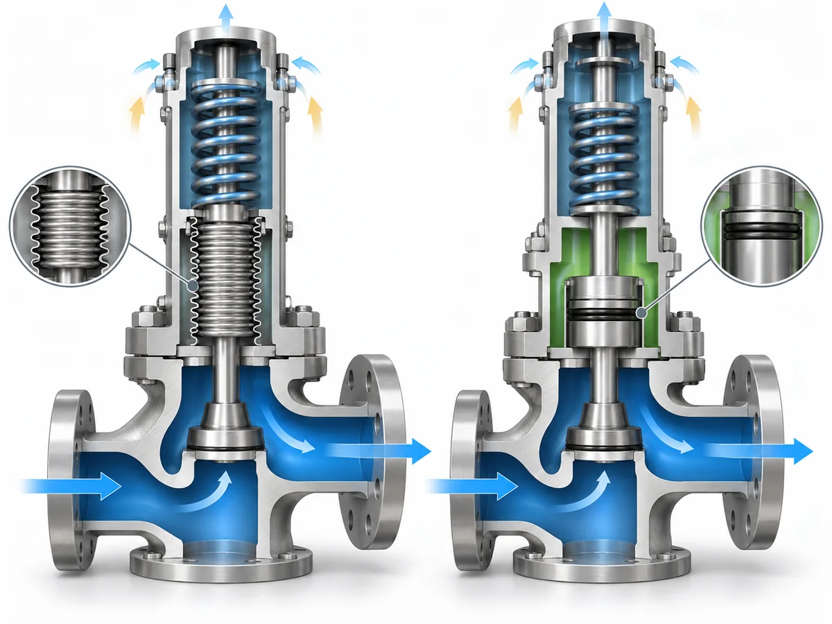
The key distinction is that back-pressure balancing and process isolation are not the
same requirement. A valve may reduce back-pressure influence without providing the same
barrier between the process medium and upper working components.
Spirax Sarco’s safety-valve installation guidance
distinguishes the bonnet-vent implications of balanced bellows and balanced piston designs.
For a piston-balanced candidate, the actual vent and sealing boundary therefore needs to be
confirmed rather than inferred from the word “balanced.”
That is why corrosive, contaminating or otherwise difficult service cannot be screened using
the label “balanced” alone. The actual bellows, piston, guide, seal and vent boundaries have to
be checked for the proposed model.
For the detailed bellows mechanism, see
how a bellows-balanced safety valve works
.
How Do Failure Modes and Maintenance Considerations Change the Choice?
Normal operation tells only half of the story. Selection should also consider what changes if the
balancing boundary degrades.
For a bellows-balanced valve, loss of bellows integrity changes the pressure boundary that provides
the intended balancing and isolation.
Spirax Sarco’s balanced safety-valve guidance
notes that bellows failure can affect valve performance and that abnormal flow at the bellows
vent can serve as a failure indication in applicable arrangements.
This is where an auxiliary balanced piston can become relevant. Some bellows designs
add a supplementary piston so that back-pressure compensation can be retained after bellows failure.
Crosby J-Series documentation
provides a manufacturer-specific example of a backup piston used with bellows-failure monitoring.
That example should not be generalized to every bellows-balanced valve.
Those features must be confirmed on the actual product. They should never be assumed from the phrase
“balanced bellows.”
Piston-balanced valves create a different maintenance question. Where the design uses piston, guide
or O-ring seals, the suitability of those sealing elements becomes part of the engineering review.
Crosby balanced-piston product documentation
provides one example of a design using defined piston and guide sealing elements. Seal material,
process compatibility, temperature range and physical condition must therefore be checked against
the actual proposed configuration rather than assumed from the architecture name.
| Review question | Balanced bellows | Piston balanced |
|---|---|---|
| Critical balancing component | Bellows | Piston and associated pressure/sealing boundary |
| If integrity is lost | Intended balancing/isolation boundary can change | Intended piston pressure boundary or movement can be affected |
| Possible degradation indication | Vent leakage or dedicated monitoring in applicable designs | Detection depends on the specific piston/vent/seal design |
| Backup balancing | Some designs add an auxiliary piston | The piston is already the primary balancing element |
| Materials to confirm | Bellows and exposed valve materials | Piston, guide and seal materials |
| Maintenance basis | Manufacturer’s bellows inspection/replacement requirements | Manufacturer’s piston/seal inspection requirements |
The correct conclusion is not that piston valves inherently “stick,” or that bellows valves
automatically “last longer.” The useful question is which component must remain functional,
how degradation can be detected, and what happens to the intended valve behavior when that
component no longer performs as designed.
When Should You Consider a Balanced Bellows or Piston Balanced Design?
Start with the service requirement, not with a preferred component.
| Application question | Initial screening direction |
|---|---|
| Must upper moving components be additionally isolated from the outlet/process medium? |
A balanced-bellows design deserves closer evaluation because the bellows can provide that additional boundary in applicable designs. |
| Would process fluid at the bonnet vent create a difficult containment or routing issue? | Compare the exact vent boundary carefully; bellows and piston designs can behave differently. |
| Does the piston candidate depend on polymer or elastomer seals? | Verify seal material, process compatibility and operating limits for the actual model. |
| Is the service dirty, viscous or capable of contaminating critical moving clearances? |
Consider whether a bellows isolation boundary provides a useful advantage, then verify the actual product construction. |
| Is bellows failure a critical project concern? |
Check whether the proposed bellows design provides failure indication, an auxiliary balancing piston or another defined failure response. |
| Is temperature a major constraint? |
Compare the actual bellows, piston, seal and valve material limits. Architecture name alone is insufficient. |
| Is back pressure high or strongly variable? |
Check the manufacturer’s allowable back-pressure envelope and capacity basis for the exact candidate rather than assuming either architecture wins. |
| Is the project requirement performance-based rather than construction-based? |
State the required back-pressure behavior, isolation, venting and service conditions and require the supplier to justify the proposed architecture. |
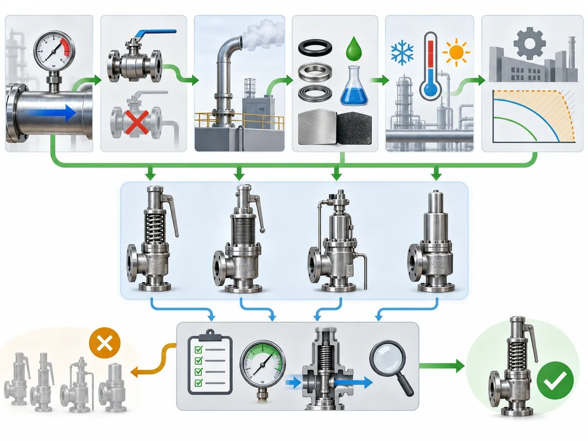
This prevents two common oversimplifications:
high back pressure does not automatically mean “choose piston,” and corrosive or
difficult service does not automatically mean “choose bellows.”
The decisive evidence is the actual product configuration and operating envelope, not the
architecture label alone. Architecture is a screening layer, not final project approval.
For the wider choice among pressure-relief-valve constructions, see the
broader safety valve selection guide
.
What Should You Confirm Before Specifying or Requesting a Quote?
A useful RFQ should describe the relief duty and installed conditions rather than simply state
“balanced bellows” or “balanced piston.”
Provide the service and relief-duty basis
Identify the protected equipment, relieving medium and phase, set-pressure basis, relevant
relieving conditions and required relieving capacity established by the project’s sizing work.
This architecture comparison does not replace that sizing basis.
Define the back-pressure condition
- Expected superimposed back pressure
- Expected built-up back pressure
- Whether the superimposed component is constant or variable
- The relevant maximum outlet-pressure condition
Define the fluid, material and installation constraints
State the process medium, phase, temperature and any corrosive, dirty, viscous or compatibility
conditions that could affect bellows material, piston construction, guide components, seals or
other exposed pressure-boundary materials.
Also define the discharge destination and whether the bonnet vent can discharge locally,
must be routed elsewhere, or is subject to other project restrictions.
Ask the supplier to identify and justify the proposed architecture
| Supplier confirmation | Why it matters |
|---|---|
| Balanced bellows, standalone balanced piston, or other construction | Prevents taxonomy and specification errors |
| Role of any auxiliary piston | Distinguishes primary balancing from bellows-failure backup |
| Permissible back-pressure envelope | Architecture name alone does not establish the model limit |
| Applicable capacity correction | Back pressure may still influence supported relieving capacity |
| Bonnet and vent arrangement | Defines the pressure reference and possible fluid path |
| Bellows, piston and seal materials | Required for process and temperature compatibility |
| Pressure and temperature limits | Must come from the exact proposed configuration |
| Failure-detection or backup features | Must not be assumed from the valve-family name |
| Capacity and supporting documentation | Needed to verify the actual relief duty |
| Applicable certification or conformity evidence | Must match the proposed model and project requirement |
For projects using API or ASME frameworks,
API 520 Part I
addresses pressure-relief-device sizing and selection, while
ASME BPVC Section XIII
provides the broader overpressure-protection framework. The code, specification and edition
actually adopted by the project remain controlling.
For a broader explanation of that standards context, see the
ZOBAI safety valve standards guide
.