比较波纹管平衡式与活塞平衡式安全阀在背压特性、排放、隔离、失效模式、使用限制及询价核查方面的差异。.

平衡波纹管式和活塞平衡式安全阀解决的是同一类问题:降低出口背压对直接作用弹簧式安全阀的影响。二者通过不同的压力边界和平衡元件来实现。.
A 波纹管平衡式安全阀 利用波纹管的有效面积作为平衡结构的一部分。A 活塞平衡式阀门 利用有效活塞面积及其相关的密封和排放结构。该差异会影响工艺隔离、阀盖排放行为、材料兼容性、故障响应和维护。.
并不存在通用的最优方案。更合适的选择取决于实际背压工况、使用介质、所需隔离、温度、排放限制,以及具体阀门制造商所支持的工作范围。.
首先应明确一个术语问题: 独立的活塞平衡式阀门与配备辅助平衡活塞的波纹管平衡式阀门并不相同。. Spirax Sarco 的安全阀指南 对活塞式和波纹管式平衡安全阀进行了区分,同时也描述了部分波纹管设计中使用的辅助活塞。.
波纹管平衡式与活塞平衡式:究竟在比较什么?
有三种结构容易被混淆。.
A 波纹管平衡式安全阀 采用波纹管作为主要平衡元件。.
其有效面积参与抵消出口压力原本会
施加在运动组件上的作用力。.
A 独立活塞平衡式阀门 采用活塞作为主要平衡
元件。活塞面积及其上方压力经过布置,使相关背压
作用力相互抵消,而不是像常规
弹簧式安全阀那样产生相同的不平衡力。.
第三种结构是 带辅助平衡活塞的波纹管平衡式安全阀.
此时活塞并不自动作为常规的主要平衡机构。部分设计采用
作为波纹管失效时的备用措施。.
在阅读图纸或编制询价单(RFQ)时,这一区分非常重要。看到阀内有一个活塞
并不能单独证明该阀就是独立的活塞平衡式结构。.
活塞平衡式弹簧安全阀也不应与
活塞式先导泄压阀. 混淆。在先导式结构中,,
先导压力控制主阀;这是不同的工作架构。.
关于该阀门类别的更广泛定义,请参见
背压平衡式安全阀的含义
.
波纹管与活塞设计如何以不同方式平衡背压?
背压会改变作用在弹簧式泄压阀上的力。.
平衡结构改变的是受力关系,而不是简单地增大弹簧力。.
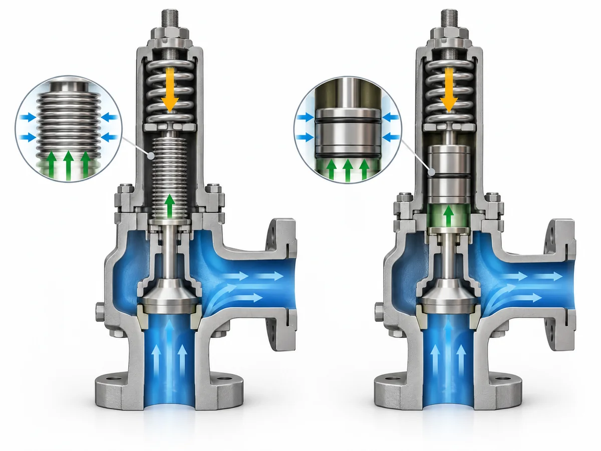
在 活塞平衡式设计, 中,活塞上的有效作用面积被设置为
相对于喷嘴或阀座区域,使方向相反的背压作用力能够相互抵消。.
活塞上方的压力也必须具有预期的参考基准,这使得阀盖
和排放结构成为平衡系统的一部分。.
A 波纹管平衡式结构 通过波纹管的有效
作用面积达到相同的总体目标。波纹管可防止出口压力产生相同的不平衡
作用力施加在阀瓣组件的相应部位上。.
其共同原理是压力-面积平衡;实现该原理的物理部件是
平衡面积不同。.
该词 平衡式 并不意味着阀门可以承受无限背压,,
排量永远不会变化,或者可以忽略出口管道。实际设计中
仍存在各制造商特定的运行范围,在特定背压工况下
可能需要进行排量修正。.
两个背压术语应保持区分。.
叠加背压 在出口侧独立于当前
泄放流量而存在。. 积聚背压 随着泄放流量在下游系统中产生压力
而逐渐形成。.
工程问题并不只是阀门是否为“平衡式”。而是该
所选设计在实际背压条件下仍保持适用,
已安装系统。.
关于更广泛的系统影响,请参见
背压如何影响弹簧式安全阀
.
压力边界、排放和工艺隔离有何不同?
背压补偿只是对比的一部分。流体边界围绕
平衡元件可能同样重要。.
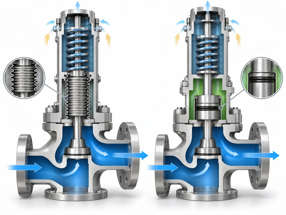
平衡波纹管可在出口/工艺区域之间提供额外的物理屏障
以及上部组件,如阀杆导向或弹簧。这种隔离功能是独立的
与波纹管在平衡背压力方面的作用不同。.
活塞平衡设计以不同方式建立边界。一些设计使用密封件围绕
活塞或导向,活塞上方的腔室必须保持预期的压力基准。.
这使阀盖排放口成为阀门结构中具有功能作用的组成部分。.
| 对比项 | 平衡波纹管 | 活塞平衡式 |
|---|---|---|
| 主要平衡元件 | 波纹管有效面积 | 活塞有效面积 |
| 上部隔离 | 在适用设计中可提供附加隔离 | 取决于活塞、导向与密封结构 |
| 压力基准 | 必须保持预期的波纹管/阀盖边界 | 必须保持活塞上方设定的压力 |
| 排放口考量 |
完好的波纹管将阀盖排放口与正常出口流体边界隔开;; 波纹管失效会改变该状态 |
必须核查实际设计中工艺介质是否与阀盖排放口连通 |
| 密封依赖性 | 波纹管构成运动压力边界的一部分 | 部分设计依靠活塞/导向密封元件 |
| 选型核查 | 波纹管材质与完整性 | 活塞/密封材质、状态及排放口压力边界 |
The key distinction is that back-pressure balancing and process isolation are not the
same requirement. A valve may reduce back-pressure influence without providing the same
barrier between the process medium and upper working components.
Spirax Sarco’s safety-valve installation guidance
distinguishes the bonnet-vent implications of balanced bellows and balanced piston designs.
For a piston-balanced candidate, the actual vent and sealing boundary therefore needs to be
confirmed rather than inferred from the word “balanced.”
That is why corrosive, contaminating or otherwise difficult service cannot be screened using
the label “balanced” alone. The actual bellows, piston, guide, seal and vent boundaries have to
be checked for the proposed model.
For the detailed bellows mechanism, see
how a bellows-balanced safety valve works
.
How Do Failure Modes and Maintenance Considerations Change the Choice?
Normal operation tells only half of the story. Selection should also consider what changes if the
balancing boundary degrades.
For a bellows-balanced valve, loss of bellows integrity changes the pressure boundary that provides
the intended balancing and isolation.
Spirax Sarco’s balanced safety-valve guidance
notes that bellows failure can affect valve performance and that abnormal flow at the bellows
vent can serve as a failure indication in applicable arrangements.
This is where an auxiliary balanced piston can become relevant. Some bellows designs
add a supplementary piston so that back-pressure compensation can be retained after bellows failure.
Crosby J-Series documentation
provides a manufacturer-specific example of a backup piston used with bellows-failure monitoring.
That example should not be generalized to every bellows-balanced valve.
Those features must be confirmed on the actual product. They should never be assumed from the phrase
“balanced bellows.”
Piston-balanced valves create a different maintenance question. Where the design uses piston, guide
or O-ring seals, the suitability of those sealing elements becomes part of the engineering review.
Crosby balanced-piston product documentation
provides one example of a design using defined piston and guide sealing elements. Seal material,
process compatibility, temperature range and physical condition must therefore be checked against
the actual proposed configuration rather than assumed from the architecture name.
| 审查问题 | 平衡波纹管 | 活塞平衡式 |
|---|---|---|
| Critical balancing component | 波纹管 | Piston and associated pressure/sealing boundary |
| If integrity is lost | Intended balancing/isolation boundary can change | Intended piston pressure boundary or movement can be affected |
| Possible degradation indication | Vent leakage or dedicated monitoring in applicable designs | Detection depends on the specific piston/vent/seal design |
| Backup balancing | Some designs add an auxiliary piston | The piston is already the primary balancing element |
| Materials to confirm | Bellows and exposed valve materials | Piston, guide and seal materials |
| Maintenance basis | Manufacturer’s bellows inspection/replacement requirements | Manufacturer’s piston/seal inspection requirements |
The correct conclusion is not that piston valves inherently “stick,” or that bellows valves
automatically “last longer.” The useful question is which component must remain functional,
how degradation can be detected, and what happens to the intended valve behavior when that
component no longer performs as designed.
When Should You Consider a Balanced Bellows or Piston Balanced Design?
Start with the service requirement, not with a preferred component.
| Application question | Initial screening direction |
|---|---|
| Must upper moving components be additionally isolated from the outlet/process medium? |
A balanced-bellows design deserves closer evaluation because the bellows can provide that additional boundary in applicable designs. |
| Would process fluid at the bonnet vent create a difficult containment or routing issue? | Compare the exact vent boundary carefully; bellows and piston designs can behave differently. |
| Does the piston candidate depend on polymer or elastomer seals? | Verify seal material, process compatibility and operating limits for the actual model. |
| Is the service dirty, viscous or capable of contaminating critical moving clearances? |
Consider whether a bellows isolation boundary provides a useful advantage, then verify the actual product construction. |
| Is bellows failure a critical project concern? |
Check whether the proposed bellows design provides failure indication, an auxiliary balancing piston or another defined failure response. |
| Is temperature a major constraint? |
Compare the actual bellows, piston, seal and valve material limits. Architecture name alone is insufficient. |
| Is back pressure high or strongly variable? |
Check the manufacturer’s allowable back-pressure envelope and capacity basis for the exact candidate rather than assuming either architecture wins. |
| Is the project requirement performance-based rather than construction-based? |
State the required back-pressure behavior, isolation, venting and service conditions and require the supplier to justify the proposed architecture. |
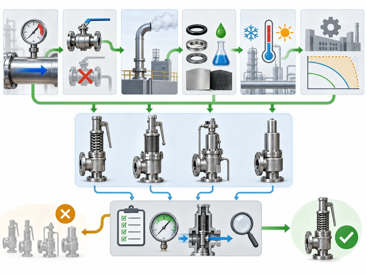
This prevents two common oversimplifications:
high back pressure does not automatically mean “choose piston,” and corrosive or
difficult service does not automatically mean “choose bellows.”
The decisive evidence is the actual product configuration and operating envelope, not the
architecture label alone. Architecture is a screening layer, not final project approval.
For the wider choice among pressure-relief-valve constructions, see the
broader safety valve selection guide
.
What Should You Confirm Before Specifying or Requesting a Quote?
A useful RFQ should describe the relief duty and installed conditions rather than simply state
“balanced bellows” or “balanced piston.”
Provide the service and relief-duty basis
Identify the protected equipment, relieving medium and phase, set-pressure basis, relevant
relieving conditions and required relieving capacity established by the project’s sizing work.
This architecture comparison does not replace that sizing basis.
Define the back-pressure condition
- Expected superimposed back pressure
- Expected built-up back pressure
- Whether the superimposed component is constant or variable
- The relevant maximum outlet-pressure condition
Define the fluid, material and installation constraints
State the process medium, phase, temperature and any corrosive, dirty, viscous or compatibility
conditions that could affect bellows material, piston construction, guide components, seals or
other exposed pressure-boundary materials.
Also define the discharge destination and whether the bonnet vent can discharge locally,
must be routed elsewhere, or is subject to other project restrictions.
Ask the supplier to identify and justify the proposed architecture
| Supplier confirmation | 重要性 |
|---|---|
| Balanced bellows, standalone balanced piston, or other construction | Prevents taxonomy and specification errors |
| Role of any auxiliary piston | Distinguishes primary balancing from bellows-failure backup |
| Permissible back-pressure envelope | Architecture name alone does not establish the model limit |
| Applicable capacity correction | Back pressure may still influence supported relieving capacity |
| Bonnet and vent arrangement | Defines the pressure reference and possible fluid path |
| Bellows, piston and seal materials | Required for process and temperature compatibility |
| Pressure and temperature limits | Must come from the exact proposed configuration |
| Failure-detection or backup features | Must not be assumed from the valve-family name |
| Capacity and supporting documentation | Needed to verify the actual relief duty |
| Applicable certification or conformity evidence | Must match the proposed model and project requirement |
For projects using API or ASME frameworks,
API 520 第 I 部分
addresses pressure-relief-device sizing and selection, while
ASME BPVC 第 XIII 卷
provides the broader overpressure-protection framework. The code, specification and edition
actually adopted by the project remain controlling.
For a broader explanation of that standards context, see the
ZOBAI safety valve standards guide
.