Erfahren Sie, wie Sie Filter, Messleitungen und Dichtungen an pilotgesteuerten Sicherheitsventilen prüfen und wie Sie Funktionstests mit den erforderlichen Nachweisen vor der Wiederinbetriebnahme abstimmen.

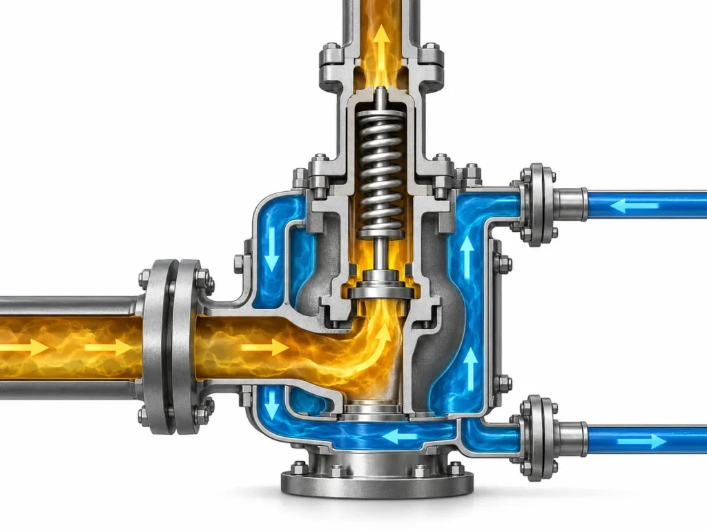
Ein pilotgesteuertes Sicherheitsventil sollte nicht so gewartet werden, als wäre der Pilot
lediglich ein Zubehörteil, das an das Hauptventil geschraubt ist. Der Pilot, Filter, Mess-
oder Versorgungsanschlüsse, Steuerleitungen, Dichtungen und das Hauptventil bilden ein Druckregel-
system. Verunreinigungen, Leckagen, Querschnittsverengungen oder ein falsch wiederhergestellter Druck-
pfad können von Bedeutung sein, selbst wenn das Hauptventilgehäuse selbst wartungsfähig erscheint.
Der zweite Wartungsfehler besteht darin, jeden “Test” nach der Wartung als gleichwertig zu behandeln.
Eine Überprüfung des Pilot-Einstelldrucks, eine Dichtheitsprüfung des Sitzes, eine Dichtheitsprüfung der Baugruppe,
eine Funktionsprüfung der kompletten Baugruppe und eine Durchflusskapazitätsprüfung beantworten unterschiedliche
Fragen. Ein PASS-Ergebnis ist nur im Rahmen des Tests aussagekräftig, der es hervorgebracht hat.
Dieser Artikel folgt daher zwei Regeln:
- Den tatsächlich am Ventil installierten Pilot-/Steuerpfad inspizieren.
- Den Test auf den benötigten Nachweis vor der Wiederinbetriebnahme abstimmen.
Dieser Artikel verwendet Pilotgesteuertes Sicherheitsventil als Arbeitsbegriff.
Hersteller- und Normendokumentation kann auch
Pilotgesteuertes Druckentlastungsventil, POSV oder POSRV.
ISO 4126-4 ist die ISO-Produktnorm speziell für pilotgesteuerte Sicherheitsventile;
ISO legt fest, dass es sich um eine Produktnorm handelt, nicht um eine Anwendungsnorm. Sie ersetzt daher
nicht das modellspezifische Wartungshandbuch, die Betreiberanweisung oder
die behördlichen Anforderungen an die Wiederinbetriebnahme. Siehe
ISO 4126-4.
Wenn der Betriebsablauf selbst noch nicht klar ist, siehe
wie ein pilotgesteuertes Sicherheitsventil funktioniert.
Vor der Wartung die Ventilkonfiguration und den Ist-Zustand bestätigen
Vor dem Reinigen eines Filters, dem Trennen von Leitungen oder dem Austausch von Dichtungen,
genau festzustellen, mit welcher Hauptventil-, Pilot- und Messanordnung Sie arbeiten.
Pilotgesteuerte Ausführungen unterscheiden sich darin, wie der Eingangsdruck zum Pilot gelangt, ob die Messung
integriert oder fernverlegt ist, wie der Dome-/Steuerdruck geführt wird, wo Filter eingebaut sind
und welche Komponenten als separate Baugruppen gewartet oder geprüft werden.
Ein Wartungsschritt, der für eine Anordnung gilt, darf nicht
automatisch auf eine andere übertragen werden. Das Handbuch der Anderson Greenwood Serie 727 zum Beispiel,
enthält Anordnungen mit interner Messung, Fernmessung und Snubber und gibt spezifische
Anweisungen für diese Konfigurationen. Das Handbuch Consolidated 2900-40 von Baker Hughes
unterscheidet ebenso Fernmessungs- und Messring-Optionen. Diese Hersteller
Beispiele stützen die gleiche allgemeine Wartungsregel: den genauen Druckpfad identifizieren
bevor er geöffnet oder wiederhergestellt wird. Siehe
Anderson Greenwood Series 727 maintenance instructions
und
Baker Hughes Consolidated 2900-40 POSRV-Handbuch.
Zunächst bestätigen:
- Identifikation von Hauptventil und Pilotventil, einschließlich Modell-/Serieninformationen, die zur Beschaffung des korrekten Verfahrens und der Ersatzteile erforderlich sind;
- die geltenden Wartungsanweisungen des Herstellers und die Betreiberprozedur;
- die Messanordnung, einschließlich Fernmessung, Dämpfungsglieder oder Feldtestanschlüsse, sofern verwendet;
- Prozessmedium und Betriebsbedingungen im Hinblick auf Verunreinigung, Korrosion, Elastomerverträglichkeit und Ablagerungen;
- warum das Ventil ausgebaut, geprüft oder geöffnet wurde;
- der Ist-Zustand vor der Reinigung oder Demontage, die Beweise beseitigen würde; und
- relevante frühere Prüf- oder Wartungsaufzeichnungen, sofern verfügbar.
Arbeiten am druckführenden System oder am Pilotsystem müssen den geltenden
Absperr- und Druckentlastungsverfahren der Anlage und des Herstellers. Die Serie 727
Handbuch warnt beispielsweise, dass die Anlage vor dem Ventil druckentlastet werden muss
Ausbau oder Demontage sowie Hinweise darauf, dass Fluid im Dome-Raum eingeschlossen bleiben kann
eines pilotgesteuerten Sicherheitsventils. Das ist eine produktspezifische Anweisung, keine
universelle Absperrreihenfolge. Der Absperrplan der Anlage muss der tatsächlichen
Installation und den Gefahren entsprechen.
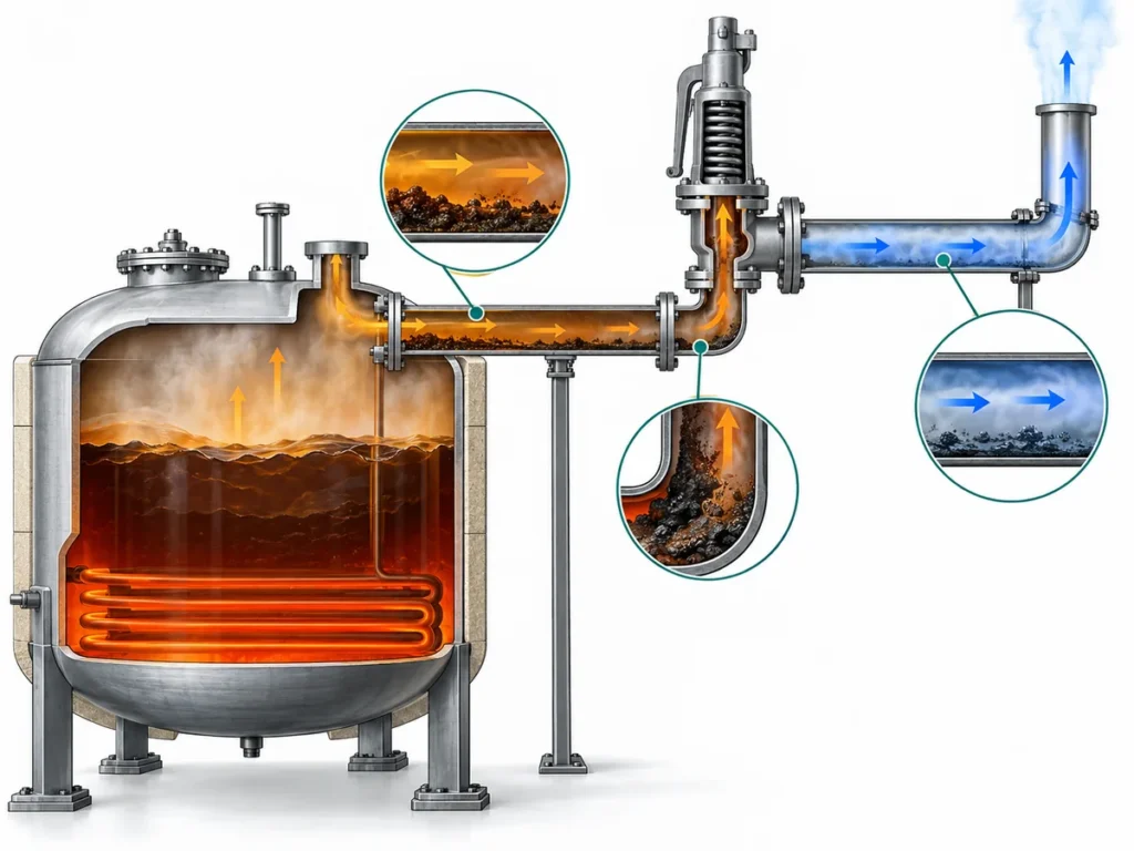
Den vorgefundenen Zustand bevor die Reinigung nützliche
Nachweise entfernt. Ein beladener Filter, Korrosionsprodukt in einem Messanschluss, Leckage an
a pilot connection, an incorrectly connected line or an unexpected deposit can
explain why the assembly behaved abnormally. API RP 576 covers inspection and
repair practices for pressure-relieving devices, including pilot-operated PRVs,
and its current API catalog entry emphasizes inspection/repair practices intended
to support proper device performance. See
API RP 576 in the API refining catalog.
Für das übergreifende Instandhaltungsprogramm des gesamten Ventils, die Inspektionsplanung und
den Kontext von vorgefundenem Zustand und Zustand nach der Arbeit siehe
Leitfaden zur Wartung und Inspektion von Sicherheitsventilen.
The present article stays focused on the pilot/control path and the evidence
needed after work on filters, tubing, seals and functional tests.
Instandhaltungsentscheidung: Do not diagnose or replace the component
until the configuration around it is known well enough to explain what pressure
the component should receive, retain, vent or transmit.
Filter als Teil des Pilotsteuerpfads prüfen, nicht als isoliertes Bauteil
On pilot-operated valve designs that use a filter in the sensing or pilot-supply
path, filter condition can tell you more than whether the filter itself needs
attention. A filter is part of the pressure path feeding the pilot system.
If that path is restricted, the problem is not “dirty hardware” in the abstract;
it is whether the pilot receives and responds to the pressure signal in the way
the design requires.
Ein verunreinigter Filter nicht prove that the pilot is blocked.
It does provide evidence that the same contaminant may have reached adjacent
passages, fittings or pilot components. The maintenance response should therefore
dem Kontaminationspfad folgen, statt am ersten verschmutzten Bauteil haltzumachen.
Herstelleranweisungen zeigen ebenfalls, warum es keine universelle Filterregel gibt.
Im Handbuch der Anderson Greenwood Serie 727 wird die Filterbaugruppe des Hauptventils
zur Reinigung und Prüfung ausgebaut und kann wiederverwendet werden, wenn sie nicht beschädigt ist,
während die zugehörige Dichtung des Filteranschlusses verworfen und ersetzt wird. Andere Ventil-
baureihen können andere Filteranordnungen und Ersatzregeln verwenden. Die richtige
Maßnahme ist diejenige, die für die genaue Ventilkonfiguration festgelegt ist, nicht “immer wiederverwenden”
oder “immer ersetzen”.”
| Filterbefund | Was geändert werden sollte |
|---|---|
| Sauber und unbeschädigt |
Die verbleibende erforderliche Prüfung des Pilotpfads fortsetzen. Ein sauberer Filter beweist nicht, dass Messleitungen, Fittings, Pilotdichtsitze oder Steuer- anschlüsse frei von Verstopfungen oder Leckagen sind. |
| Erhebliche Verunreinigung |
Den angeschlossenen Steuerpfad auf damit zusammenhängende Kontamination oder Verschmutzung und dokumentieren Sie nach Möglichkeit die Art des Schmutzes vor der Reinigung. |
| Beschädigt oder nach dem geltenden Verfahren nicht akzeptabel |
Befolgen Sie die modellspezifische Austauschanforderung und prüfen Sie das korrekte Ersatzteil. |
| Wiederholte starke Verunreinigung |
Prüfen Sie, warum weiterhin Schmutz in das Pilotsystem gelangt, anstatt jeden Filterwechsel als isolierte Wartungsmaßnahme zu behandeln. |
Die Wartungsfrequenz hat dieselbe Grenze. API RP 576 ist eine Inspektionspraxis-
Referenz, aber weder dieser Geltungsbereich noch die hier geprüften Herstellerhandbücher
stützen ein universelles Filterreinigungsintervall für jedes pilotgesteuerte Ventil.
Die Frequenz sollte auf dem anwendbaren Verfahren, der Beanspruchung des Betriebs, der Kontaminations-
historie und dem Inspektionsprogramm des Betreibers basieren.
Der Filterzustand kann daher diagnostischer Nachweis über die Umgebung sein,
die das Pilotsystem sieht, nicht nur eine Ordnungsmaßnahme.
Prüfung der Sensor- und Steuerleitungen auf Verstopfung, Leckage und Fehler beim Wiederzusammenbau
Nicht jedes kleine Rohr an einem pilotgesteuerten Sicherheitsventil hat denselben Zweck.
Je nach Ausführung kann die Dokumentation eine Druckmessleitung,
Pilotversorgungsanschluss, Dom-/Steuerleitung, Fernmessanschluss, Abblaseleitung
connection and field-test connection. Before loosening a fitting, identify what
pressure that line is supposed to communicate and to which component.
Manufacturer maintenance instructions reinforce this point. The Series 727 manual
calls for inspection of remote-sense and snubber fittings for blockage in applicable
configurations. Baker Hughes’ 2900-40 manual shows that remote sensing is its standard
pilot pressure connection while a sensing-ring option changes the pickup location.
These are design-specific arrangements, but together they show why “the tubing looks
similar” is not enough to establish correct routing.
Probleme an Leitungen sollten daher nach Ausfallart getrennt werden.
| Reparatur möglich? | Warum es wichtig ist | Wartungsprüfung |
|---|---|---|
| Verstopfung oder Blockierung |
The intended pressure signal or pilot-supply path may be delayed, attenuated or prevented from reaching the intended component. |
Inspect the affected passage, fitting, snubber/filter and connected pilot components using the applicable procedure. |
| Leckage |
Pressure integrity in the sensing, dome or control path may be lost. The effect depends on where the leak is located in the circuit. |
Identify the leaking joint/component and perform the specified post-assembly leakage check after correction. |
| Knick, Korrosion oder mechanische Beschädigung |
The flow area or mechanical integrity may no longer match the intended Konfiguration überprüft werden. |
Repair or replace with the specified material, size and routing from approved documentation. |
| Lockere oder fehlerhafte Wiederverbindung | The valve may no longer sense, load or vent pressure through the intended path. |
Compare routing and connection points with the correct valve/manifold documentation, then leak-check the restored connection as required. |
| Nicht verifizierte Änderung an einer Fernmessleitung | The sensing point or line characteristics may no longer match the engineered configuration. |
Return the arrangement for engineering/manufacturer review instead of normalizing the modification during maintenance. |
Der Unterschied zwischen Querschnittsverengung und Leckage
is important because the failure mechanisms differ. A restricted path can impair
pressure communication. A leak changes pressure integrity. The same symptom at the
valve may therefore have different causes, and the maintenance evidence needed to
close the job is not interchangeable.
Remote sensing deserves particular discipline. Do not shorten, resize, reroute or
reconnect a sensing line merely because the new arrangement physically fits. The
sensing point, line routing, fittings and any filter/snubber arrangement are part of
the approved pressure path.
Wartungsregel: Restore the documented pressure path, then verify
the applicable connections for restriction and leakage. If the approved routing
cannot be established, hold the valve for engineering or manufacturer review.
For maintenance closeout, “the tubing looks fine” is weaker evidence than confirming
that the correct pressure path has been restored and checked for the restriction and
leakage modes relevant to the applicable procedure.
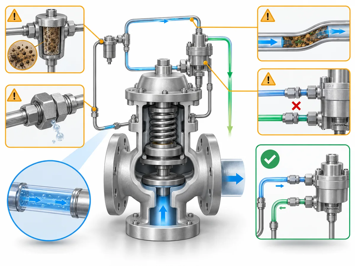
Dichtungen nach Einbauort, Zustand und Einsatzkompatibilität bewerten
A seal decision should not begin and end with, “Does this O-ring look damaged?”
Pilot-operated valves contain seals in different functions: some retain dome or
pilot pressure, some seal the main valve, and some seal fittings or filter/manifold
joints. The consequence of damage, wrong material or wrong reuse decision depends
on where the seal sits in the pressure-control system.
Manufacturer repair instructions also do not treat every sealing component the same
way. The Anderson Greenwood Series 727 manual is a useful example: it allows the
filter assembly to be reused if undamaged, while it specifically tells the technician
to discard certain seals and other listed parts during the applicable repair steps.
Its repair kits are selected by valve model/serial information. That is exactly why a
generic “reuse if it looks good” rule is not defensible.
Two shortcuts should therefore be avoided:
Reuse every seal that still looks good.
und
Replace every seal on every pilot-operated valve whenever the valve is opened.
Instead, separate four questions.
1. Which seal is it?
Identify the location and function of the part. A pilot seat/seal, main-valve sealing
element, dome seal, filter-port seal and tubing/connection seal should not inherit the
same maintenance rule simply because each is called a “seal.”
2. Is the part and material correct?
Pilot-operated valve families can use different soft goods or metallic sealing
components for different pressure, temperature and process conditions. A replacement
should match the approved bill of materials or repair kit for the exact configuration,
not merely the apparent dimensions of the removed part.
For deeper material-selection context, see the
Leitfaden zur Materialauswahl für Sicherheitsventile.
3. Is its condition acceptable?
Inspect for the damage modes addressed by the applicable manufacturer procedure:
cuts, extrusion, compression damage, wear, corrosion or deposit-related damage where
relevant. Appearance can identify physical deterioration, but it cannot prove the
material grade, prior chemical attack, or compatibility with the process.
4. Does the applicable procedure permit reuse?
This is separate from appearance. If the model-specific procedure requires
replacement during the applicable service operation, an apparently intact part is
not evidence for reuse. Conversely, a part the manufacturer permits to be cleaned,
inspected and reused should not be subjected to an invented universal replacement rule.
Seal decision sequence:
identity → function → approved material/configuration → physical condition →
permitted reuse/replacement → post-assembly leakage/functional verification.
Match the Functional Test to What You Need to Prove
A post-maintenance test is only as broad as its test scope. Instead of asking only,
“Did the valve pass?” ask:
Which test was performed, which part of the pilot/main-valve system did it
exercise, what acceptance basis was used, and what remains untested?
The standards have different roles. The current API catalog lists
API RP 576
as an inspection and repair practice covering pilot-operated PRVs;
API 527
addresses seat tightness, with the current API digital catalog listing API 527,
5th Edition, as the seat-tightness standard; and
API’s digital catalog
confirms the current API 527 entry.
ASME PTC 25-2023
is a performance test code for pressure relief devices and includes flow-capacity,
in-service and bench testing. These documents do not make a pilot set-pressure
check, seat-leakage test, assembly function test and capacity test interchangeable.
Manufacturer procedures make the same distinction at the equipment level. The
Anderson Greenwood Series 727 manual separates valve-assembly leak tests, pilot
set-pressure testing, and pilot/manifold internal leak testing. Its field test
procedure can verify pilot set pressure while the main valve does not cycle during
that procedure. That is strong evidence for a narrow but important maintenance rule:
a valid pilot test proves the pilot variable it actually exercises; it does
not automatically prove full main-valve operation or rated flow capacity.
| Check or test | What the result can support | Was es nicht automatisch beweist |
|---|---|---|
| Visual / configuration inspection | Visible condition, correct routing, part identity and assembly observations within the inspection scope | Set pressure, seat tightness, pilot response under pressure or rated flow capacity |
| Pilot/set-pressure verification | Pilot actuation or set-pressure behavior under the approved test method | Main-valve cycle, seat tightness, rated flow capacity or installed-system acceptance unless the procedure also tests those items |
| Seat-tightness / leakage test | Leakage performance for the seat or connections covered by the applicable test basis | Complete pilot/main-valve functional performance or flow capacity |
| Complete-assembly functional test | Defined operation/integrity of the assembled pilot and main valve under that procedure | Certified flow capacity unless capacity is actually tested under the required basis |
| Flow-capacity test | Flow performance under the defined test conditions | Correct field sensing-line routing, installation condition or every maintenance detail not represented in the test setup |
Pilot Set-Pressure or Pilot-Function Verification
On applicable designs, a field-test connection can allow pilot or set-pressure
behavior to be checked without reproducing every installed operating condition.
The Series 727 manual provides a field-test arrangement in which the pilot can be
pressurized and its pop/set behavior observed while the main valve does not cycle
during that procedure. That distinction should be preserved in the maintenance record.
A useful record is therefore not simply “Pilot test: PASS.” It should identify the
valve/pilot, the test method, the set-pressure basis being checked, the medium and
condition required by the procedure, and the function that was nicht exercised.
Do not import the Series 727 test pressures, warm-up periods or tolerances into another
valve family. Those values are model/procedure-specific. Use the correct manual and
project acceptance basis for the valve being maintained.
Seat-Tightness and Leakage Testing
Seat-tightness testing answers a leakage question. API Standard 527 is specifically
titled Sitzdichtheit von Druckentlastungsventilen, and API’s current catalog
lists it for pressure-relief-valve seat tightness. That makes it appropriate evidence
for a seat-leakage conclusion within its scope—not for the broader statement that the
pilot/main-valve control system has been functionally verified.
Manufacturer procedures may also require connection or internal leak checks that are
outside the main-seat leakage question. The Series 727 manual, for example, separates
external-joint leakage, pilot/manifold internal seat tightness and other assembly checks.
The maintenance record should say which leakage path was tested.
Complete-Valve Functional Verification
A complete-assembly functional test is broader than a pilot-only set-pressure check
because it can exercise the interaction between the pilot and main valve under the
approved procedure. It is still bounded by the setup. If the procedure does not measure
rated flow capacity, the result should not be reported as capacity certification.
Baker Hughes’ Consolidated 2900-40 manual contains a distinct functional-testing
section and model-specific instructions for sensing/filter options. That is another
reminder that the exact functional test depends on the valve configuration. Use the
procedure for the actual assembly rather than creating a generic test sequence from
another manufacturer’s manual.
Beweisregel: A complete-assembly functional test proves the
functions included in that approved procedure—not every characteristic of the
installed relief system.
What a Field or Functional Test Does Not Prove
The largest post-maintenance interpretation error is to expand a narrow PASS result
beyond the question that was tested.
- Pilot set-pressure verification ≠ rated capacity evidence.
- Seat-tightness PASS ≠ complete functional proof.
- Complete-assembly functional test ≠ flow-capacity certification.
- Bench or field valve test ≠ proof that the entire installed sensing/control system is restored correctly unless that configuration is represented and checked.
For maintenance records and engineering review, document enough information to answer:
- What test was performed and under which approved procedure?
- What valve/pilot configuration was tested?
- What pressure path, seat, connection or operating function was evaluated?
- What acceptance basis was used?
- What did the test not evaluate?
- Does another maintenance question still remain open?
That makes the test result usable evidence instead of a generic “PASS” label.
A broader standards overview is available in the
Leitfaden für Sicherheitsventilstandards.
Decide Whether the Valve Is Ready to Return to Service
Der Zusammenbau ist nicht mit dem Abschluss der Wartung gleichzusetzen. Die Entscheidung über die Wiederinbetriebnahme
sollte die Befunde und die vorgenommenen Korrekturen zusammenführen und berücksichtigen, ob der richtige Pilot- bzw. Steuerpfad
wiederhergestellt wurde, ob die erforderlichen Dichtungen und Bauteile verifiziert wurden und ob
die Prüfungen nach der Wartung tatsächlich die durch die Arbeiten aufgeworfenen Fragen beantworten.
Der folgende Satz von Kennzeichnungen PROCEED (FORTFAHREN) / HOLD (ZURÜCKSTELLEN) / ESCALATE (ZUR WEITEREN KLÄRUNG ESKALIEREN) bildet ein technisches
Prüfraster für diesen Artikel. Es handelt sich weder um Klassifizierungen nach API, ASME oder ISO noch um behördlich festgelegte
Klassifizierungen. Diese Kennzeichnungen ersetzen nicht das Abnahmeverfahren des Eigentümers des Ventils, des Herstellers oder das jeweils anwendbare
behördliche Abnahmeverfahren.
| Screening-Ergebnis | Verwenden Sie es, wenn |
|---|---|
| FORTFAHREN |
Der anwendbare Wartungsumfang ist vollständig abgearbeitet, die dokumentierte Konfiguration ist wiederhergestellt, die erforderlichen Teile und Werkstoffe sind verifiziert, und Bedenken hinsichtlich Leckagen oder Durchflussbehinderungen, die durch die Arbeiten aufgeworfen wurden, sind geklärt. Die erforderlichen Prüfungen nach der Wartung liefern akzeptable Nachweise zu den Fragen, zu deren Klärung sie vorgesehen waren. |
| ZURÜCKSTELLEN (HOLD) |
Es liegen weiterhin relevante Verunreinigungen, Verstopfungen, Leckagen, eine fehlerhafte Leitungsführung, eine ungeklärte Identität oder Werkstoffzuordnung der Dichtung, ein fehlgeschlagenes oder nicht eindeutiges Prüfergebnis oder ein anderer ungeklärter Wartungszustand vor. |
| ESCALATE |
The correct configuration cannot be established, repeated contamination suggests a broader service/system cause, test behavior conflicts with expected valve response, or the next step requires engineering/manufacturer input outside the validated maintenance scope. |
Before closeout, ask:
- Has a contaminated filter triggered the necessary inspection of the connected pilot path?
- Have sensing, supply, dome/control and field-test connections been restored to the documented configuration?
- Have relevant tubing/passages been checked for restriction and the reassembled pressure path checked for leakage as required?
- Are replacement or retained seals the correct parts/materials for the valve and permitted by the applicable procedure?
- Did the post-maintenance test actually examine the function that the maintenance work could have affected?
- Is each PASS result being used only within the scope of that test?
- Does any unresolved finding still require engineering, manufacturer or owner review?
A useful maintenance handoff contains more than “valve failed” or “valve repaired.”
Provide, where available, valve and pilot identification, relevant service conditions,
as-found observations, filter/tubing findings, components replaced or retained,
seal/soft-goods identification, tests performed, results/acceptance basis, and the
specific unresolved question if engineering review is still required.
That information helps the next reviewer distinguish a component maintenance issue
from a configuration, contamination, sensing-path or wider application problem.
Closeout principle: Maintenance is not complete merely because
the last part has been reassembled. It is complete when the relevant maintenance
questions have been closed with evidence appropriate to each question.
Frequently Asked Questions About Pilot Operated Safety Valve Maintenance
Can I clean a pilot filter and return the valve to service?
Not on the basis of the filter alone. Follow the exact manufacturer procedure for
cleaning or replacement, then consider whether the as-found contamination could also
have affected connected sensing/supply passages or pilot components. A clean filter
does not prove that the rest of the control path is unrestricted.
What should be checked after pilot sensing or control tubing is disconnected?
Confirm that the documented sensing/control path has been restored, the line is free
of relevant restriction or mechanical damage, and the reassembled connections meet
the required leakage/integrity checks. Remote-sensing lines should not be resized,
rerouted or reconnected to a different point without engineering or manufacturer approval.
Should every O-ring or seal be replaced whenever a pilot operated valve is opened?
There is no safe universal rule. Some manufacturer overhaul procedures require
specified seals or soft goods to be discarded and replaced, while other parts may be
inspected and reused under defined conditions. Identify the exact component, approved
material/part number and model-specific procedure before deciding.
Does a pilot set-pressure test prove the whole valve works?
Not necessarily. Some manufacturer field-test methods verify pilot set-pressure
behavior without cycling the main valve. The maintenance record should state what the
test exercised and what still requires another leak, functional or assembly check.
Does a seat-tightness test prove rated capacity?
No. Seat-tightness testing evaluates leakage under its applicable test basis.
Rated or certified flow capacity is a different performance question and should not
be inferred from a seat-tightness PASS result.
How often should a pilot operated safety valve be inspected?
A universal interval is not appropriate. Use the governing owner/jurisdictional
inspection program, the applicable manufacturer instructions, service severity,
contamination/corrosion history and prior as-found results. API RP 576 is an
inspection-practice reference for pressure-relieving devices, including pilot-operated PRVs.