Découvrez comment inspecter les filtres, les tubes de détection et les joints d'étanchéité des soupapes de sûreté pilotées, puis associez les essais fonctionnels aux preuves requises avant la remise en service.

Une soupape de sûreté pilotée ne doit pas être entretenue comme si le pilote était
simplement un accessoire boulonné sur la soupape principale. Le pilote, les filtres, les raccordements
de détection ou d'alimentation, la tuyauterie de commande, les joints et la soupape principale forment un seul système
de régulation de pression. La contamination, les fuites, les restrictions ou un circuit de pression
mal rétabli peuvent avoir des conséquences même lorsque le corps de la soupape principale semble en bon état.
La deuxième erreur de maintenance consiste à considérer chaque “ essai ” après maintenance comme équivalent.
Un contrôle de la pression de tarage du pilote, un essai d'étanchéité du siège, un essai d'étanchéité de l'assemblage,
un essai fonctionnel de l'assemblage complet et un essai de capacité de débit répondent à des
questions différentes. Un résultat RÉUSSI n'est utile que dans le cadre de l'essai qui l'a produit.
Cet article suit donc deux règles :
- Inspecter le circuit réel du pilote et de la commande installé sur la soupape.
- Adapter l'essai aux preuves nécessaires avant la remise en service.
Cet article utilise soupape de sûreté pilotée comme terme de travail.
La documentation du fabricant et des normes peut également utiliser
Soupape de sûreté pilotée, POSV ou POSRV.
L'ISO 4126-4 est la norme produit ISO spécifique aux soupapes de sûreté pilotées ;
L'ISO précise qu'il s'agit d'une norme de produit, et non d'une norme d'application. Elle ne remplace donc
pas le manuel de maintenance spécifique au modèle, la procédure du propriétaire ni
les exigences de remise en service de l'autorité compétente. Voir
ISO 4126-4.
Si la séquence de fonctionnement elle-même n'est pas encore claire, voir
comment fonctionne une soupape de sûreté pilotée.
Avant toute maintenance, confirmez la configuration de la soupape et son état initial
Avant de nettoyer un filtre, de déconnecter une tuyauterie ou de remplacer des joints,
déterminez précisément sur quel ensemble soupape principale, pilote et dispositif de détection vous intervenez.
Les conceptions pilotées diffèrent par la manière dont la pression d'entrée atteint le pilote, selon que la détection
est intégrée ou déportée, selon le cheminement de la pression de dôme/commande, l'emplacement des filtres
et les composants entretenus ou testés en tant qu'ensembles distincts.
Une étape de maintenance valable pour une configuration ne doit pas être transposée
automatiquement à une autre. Le manuel Anderson Greenwood Série 727, par exemple,
couvre les configurations à détection interne, à détection déportée et à amortisseur, et fournit des
instructions spécifiques pour ces configurations. Le manuel Baker Hughes Consolidated 2900-40
de même, distingue les options de détection à distance et de bague de détection. Ces fabricants
exemples étayent la même règle générale de maintenance : identifier le chemin de pression exact
avant de l'ouvrir ou de le remettre en service. Voir
les instructions de maintenance de la série 727 Anderson Greenwood
et
Manuel Baker Hughes Consolidated 2900-40 POSRV.
Commencez par confirmer :
- l'identification de la soupape principale et du pilote, y compris les informations de modèle/numéro de série nécessaires pour obtenir la procédure et les pièces correctes ;
- les instructions de maintenance du fabricant applicables et la procédure du propriétaire ;
- la configuration de détection, y compris la détection à distance, les amortisseurs ou les raccords d'essai sur site lorsqu'ils sont utilisés ;
- le fluide de procédé et les conditions de service pertinentes pour la contamination, la corrosion, la compatibilité des élastomères et les dépôts ;
- la raison pour laquelle la soupape a été déposée, inspectée ou ouverte ;
- l'état initial avant que le nettoyage ou le démontage n'élimine les preuves ; et
- les enregistrements pertinents des essais ou de la maintenance précédents, s'ils sont disponibles.
Les interventions sur le système sous pression ou sur le système pilote doivent respecter les procédures applicables d'isolation et de dépressurisation de
les procédures d'isolation et de dépressurisation de l'installation et du fabricant. La série 727
manuel, par exemple, avertit que le système doit être dépressurisé avant la soupape
démontage ou dépose et remarques indiquant que du fluide peut rester piégé dans l'espace du dôme
d'une soupape de sûreté pilotée. Il s'agit d'une instruction propre au produit, et non d'une
séquence d'isolement universelle. Le plan d'isolement du site doit correspondre à l'
installation réelle et aux dangers.
Préserver l' état tel que constaté avant le nettoyage élimine des
preuves utiles. Un filtre colmaté, un produit de corrosion dans un raccord de prise de pression, une fuite autour
a pilot connection, an incorrectly connected line or an unexpected deposit can
explain why the assembly behaved abnormally. API RP 576 covers inspection and
repair practices for pressure-relieving devices, including pilot-operated PRVs,
and its current API catalog entry emphasizes inspection/repair practices intended
to support proper device performance. See
API RP 576 in the API refining catalog.
Pour le programme de maintenance complet de la soupape, la planification des inspections et
le contexte tel que constaté/tel que laissé, voir le
Guide de maintenance et d'inspection des soupapes de sûreté.
The present article stays focused on the pilot/control path and the evidence
needed after work on filters, tubing, seals and functional tests.
Décision de maintenance : Do not diagnose or replace the component
until the configuration around it is known well enough to explain what pressure
the component should receive, retain, vent or transmit.
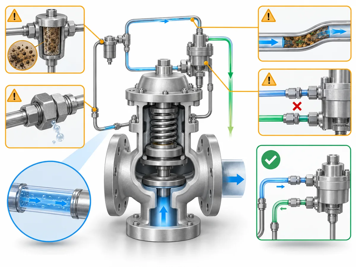
Inspecter les filtres comme partie intégrante du circuit de pilotage, et non comme un élément isolé
On pilot-operated valve designs that use a filter in the sensing or pilot-supply
path, filter condition can tell you more than whether the filter itself needs
attention. A filter is part of the pressure path feeding the pilot system.
If that path is restricted, the problem is not “dirty hardware” in the abstract;
it is whether the pilot receives and responds to the pressure signal in the way
the design requires.
Un filtre contaminé ne pas prove that the pilot is blocked.
It does provide evidence that the same contaminant may have reached adjacent
passages, fittings or pilot components. The maintenance response should therefore
suivre le trajet de contamination plutôt que de s'arrêter à la première pièce encrassée.
Les instructions du fabricant montrent également pourquoi il n'existe pas de règle universelle en matière de filtre.
Dans le manuel de la série 727 d'Anderson Greenwood, l'ensemble filtre du clapet principal est
déposé pour nettoyage et inspection et peut être réutilisé s'il n'est pas endommagé,
tandis que le joint d'orifice de filtre associé est mis au rebut et remplacé. D'autres familles
de soupapes peuvent utiliser des montages de filtre et des règles de remplacement différents. L'action
correcte est celle spécifiée pour la configuration exacte de la soupape, et non “ toujours réutiliser ”
ou “ toujours remplacer ”.”
| Constat sur le filtre | Ce qui doit changer |
|---|---|
| Propre et non endommagé |
Poursuivre l'inspection requise du reste du circuit pilote. Un filtre propre ne prouve pas que les passages de détection, les raccords, les sièges de pilote ou les connexions de commande sont exempts de restriction ou de fuite. |
| Contamination importante |
Inspecter le circuit de commande raccordé pour détecter toute contamination ou restreindre et documenter le type de contaminant avant le nettoyage lorsque cela est possible. |
| Endommagé ou inacceptable selon la procédure applicable |
Suivre l'exigence de remplacement propre au modèle et vérifier la bonne pièce de rechange. |
| Contamination importante répétée |
Examiner pourquoi la contamination continue d'atteindre le système pilote au lieu de traiter chaque entretien de filtre comme un événement de maintenance isolé. |
La fréquence de maintenance présente la même limite. L'API RP 576 est une référence de pratique d'inspection,
mais ni ce domaine d'application ni les manuels du fabricant examinés ici
ne justifient un intervalle universel de nettoyage du filtre pour chaque soupape pilotée.
La fréquence doit être basée sur la procédure applicable, la sévérité du service, l'historique de contamination
et le programme d'inspection du propriétaire.
L'état du filtre peut donc constituer une preuve diagnostique sur l'environnement
vu par le système pilote, et non un simple élément d'entretien.
Vérifier l'obstruction, les fuites et les erreurs de remontage des tubes de détection et de commande
Tous les petits tubes autour d'une soupape de sûreté pilotée n'ont pas la même fonction.
Selon la conception, la documentation peut distinguer une ligne de détection de pression,
un raccordement d'alimentation du pilote, une ligne de dôme/commande, un raccordement de détection à distance, une décharge
connection and field-test connection. Before loosening a fitting, identify what
pressure that line is supposed to communicate and to which component.
Manufacturer maintenance instructions reinforce this point. The Series 727 manual
calls for inspection of remote-sense and snubber fittings for blockage in applicable
configurations. Baker Hughes’ 2900-40 manual shows that remote sensing is its standard
pilot pressure connection while a sensing-ring option changes the pickup location.
These are design-specific arrangements, but together they show why “the tubing looks
similar” is not enough to establish correct routing.
Les problèmes de tubes doivent donc être classés par mode de défaillance.
| Trouver | Pourquoi c'est important | Contrôle de maintenance |
|---|---|---|
| Obstruction ou colmatage |
The intended pressure signal or pilot-supply path may be delayed, attenuated or prevented from reaching the intended component. |
Inspect the affected passage, fitting, snubber/filter and connected pilot components using the applicable procedure. |
| Fuite |
Pressure integrity in the sensing, dome or control path may be lost. The effect depends on where the leak is located in the circuit. |
Identify the leaking joint/component and perform the specified post-assembly leakage check after correction. |
| Pliure, corrosion ou dommage mécanique |
The flow area or mechanical integrity may no longer match the intended configuration. |
Repair or replace with the specified material, size and routing from approved documentation. |
| Reconnexion desserrée ou incorrecte | The valve may no longer sense, load or vent pressure through the intended path. |
Compare routing and connection points with the correct valve/manifold documentation, then leak-check the restored connection as required. |
| Modification non vérifiée d'une ligne de détection à distance | The sensing point or line characteristics may no longer match the engineered configuration. |
Return the arrangement for engineering/manufacturer review instead of normalizing the modification during maintenance. |
La distinction entre restriction et fuite
is important because the failure mechanisms differ. A restricted path can impair
pressure communication. A leak changes pressure integrity. The same symptom at the
valve may therefore have different causes, and the maintenance evidence needed to
close the job is not interchangeable.
Remote sensing deserves particular discipline. Do not shorten, resize, reroute or
reconnect a sensing line merely because the new arrangement physically fits. The
sensing point, line routing, fittings and any filter/snubber arrangement are part of
the approved pressure path.
Règle de maintenance : Restore the documented pressure path, then verify
the applicable connections for restriction and leakage. If the approved routing
cannot be established, hold the valve for engineering or manufacturer review.
For maintenance closeout, “the tubing looks fine” is weaker evidence than confirming
that the correct pressure path has been restored and checked for the restriction and
leakage modes relevant to the applicable procedure.
Évaluer les joints selon leur emplacement, leur état et la compatibilité avec le service
A seal decision should not begin and end with, “Does this O-ring look damaged?”
Pilot-operated valves contain seals in different functions: some retain dome or
pilot pressure, some seal the main valve, and some seal fittings or filter/manifold
joints. The consequence of damage, wrong material or wrong reuse decision depends
on where the seal sits in the pressure-control system.
Manufacturer repair instructions also do not treat every sealing component the same
way. The Anderson Greenwood Series 727 manual is a useful example: it allows the
filter assembly to be reused if undamaged, while it specifically tells the technician
to discard certain seals and other listed parts during the applicable repair steps.
Its repair kits are selected by valve model/serial information. That is exactly why a
generic “reuse if it looks good” rule is not defensible.
Two shortcuts should therefore be avoided:
Réutiliser tous les joints qui semblent encore en bon état.
et
Replace every seal on every pilot-operated valve whenever the valve is opened.
Instead, separate four questions.
1. Which seal is it?
Identify the location and function of the part. A pilot seat/seal, main-valve sealing
element, dome seal, filter-port seal and tubing/connection seal should not inherit the
same maintenance rule simply because each is called a “seal.”
2. Is the part and material correct?
Pilot-operated valve families can use different soft goods or metallic sealing
components for different pressure, temperature and process conditions. A replacement
should match the approved bill of materials or repair kit for the exact configuration,
not merely the apparent dimensions of the removed part.
For deeper material-selection context, see the
guide de sélection des matériaux des soupapes de sûreté.
3. Is its condition acceptable?
Inspect for the damage modes addressed by the applicable manufacturer procedure:
cuts, extrusion, compression damage, wear, corrosion or deposit-related damage where
relevant. Appearance can identify physical deterioration, but it cannot prove the
material grade, prior chemical attack, or compatibility with the process.
4. Does the applicable procedure permit reuse?
This is separate from appearance. If the model-specific procedure requires
replacement during the applicable service operation, an apparently intact part is
not evidence for reuse. Conversely, a part the manufacturer permits to be cleaned,
inspected and reused should not be subjected to an invented universal replacement rule.
Seal decision sequence:
identity → function → approved material/configuration → physical condition →
permitted reuse/replacement → post-assembly leakage/functional verification.
Match the Functional Test to What You Need to Prove
A post-maintenance test is only as broad as its test scope. Instead of asking only,
“Did the valve pass?” ask:
Which test was performed, which part of the pilot/main-valve system did it
exercise, what acceptance basis was used, and what remains untested?
The standards have different roles. The current API catalog lists
API RP 576
as an inspection and repair practice covering pilot-operated PRVs;
API 527
addresses seat tightness, with the current API digital catalog listing API 527,
5th Edition, as the seat-tightness standard; and
API’s digital catalog
confirms the current API 527 entry.
ASME PTC 25-2023
is a performance test code for pressure relief devices and includes flow-capacity,
in-service and bench testing. These documents do not make a pilot set-pressure
check, seat-leakage test, assembly function test and capacity test interchangeable.
Manufacturer procedures make the same distinction at the equipment level. The
Anderson Greenwood Series 727 manual separates valve-assembly leak tests, pilot
set-pressure testing, and pilot/manifold internal leak testing. Its field test
procedure can verify pilot set pressure while the main valve does not cycle during
that procedure. That is strong evidence for a narrow but important maintenance rule:
a valid pilot test proves the pilot variable it actually exercises; it does
not automatically prove full main-valve operation or rated flow capacity.
| Check or test | What the result can support | Ce qu'il ne prouve pas automatiquement |
|---|---|---|
| Visual / configuration inspection | Visible condition, correct routing, part identity and assembly observations within the inspection scope | Set pressure, seat tightness, pilot response under pressure or rated flow capacity |
| Pilot/set-pressure verification | Pilot actuation or set-pressure behavior under the approved test method | Main-valve cycle, seat tightness, rated flow capacity or installed-system acceptance unless the procedure also tests those items |
| Seat-tightness / leakage test | Leakage performance for the seat or connections covered by the applicable test basis | Complete pilot/main-valve functional performance or flow capacity |
| Complete-assembly functional test | Defined operation/integrity of the assembled pilot and main valve under that procedure | Certified flow capacity unless capacity is actually tested under the required basis |
| Flow-capacity test | Flow performance under the defined test conditions | Correct field sensing-line routing, installation condition or every maintenance detail not represented in the test setup |
Pilot Set-Pressure or Pilot-Function Verification
On applicable designs, a field-test connection can allow pilot or set-pressure
behavior to be checked without reproducing every installed operating condition.
The Series 727 manual provides a field-test arrangement in which the pilot can be
pressurized and its pop/set behavior observed while the main valve does not cycle
during that procedure. That distinction should be preserved in the maintenance record.
A useful record is therefore not simply “Pilot test: PASS.” It should identify the
valve/pilot, the test method, the set-pressure basis being checked, the medium and
condition required by the procedure, and the function that was pas exercised.
Do not import the Series 727 test pressures, warm-up periods or tolerances into another
valve family. Those values are model/procedure-specific. Use the correct manual and
project acceptance basis for the valve being maintained.
Seat-Tightness and Leakage Testing
Seat-tightness testing answers a leakage question. API Standard 527 is specifically
titled Étanchéité du siège des soupapes de sûreté, and API’s current catalog
lists it for pressure-relief-valve seat tightness. That makes it appropriate evidence
for a seat-leakage conclusion within its scope—not for the broader statement that the
pilot/main-valve control system has been functionally verified.
Manufacturer procedures may also require connection or internal leak checks that are
outside the main-seat leakage question. The Series 727 manual, for example, separates
external-joint leakage, pilot/manifold internal seat tightness and other assembly checks.
The maintenance record should say which leakage path was tested.
Complete-Valve Functional Verification
A complete-assembly functional test is broader than a pilot-only set-pressure check
because it can exercise the interaction between the pilot and main valve under the
approved procedure. It is still bounded by the setup. If the procedure does not measure
rated flow capacity, the result should not be reported as capacity certification.
Baker Hughes’ Consolidated 2900-40 manual contains a distinct functional-testing
section and model-specific instructions for sensing/filter options. That is another
reminder that the exact functional test depends on the valve configuration. Use the
procedure for the actual assembly rather than creating a generic test sequence from
another manufacturer’s manual.
Règle de preuve : A complete-assembly functional test proves the
functions included in that approved procedure—not every characteristic of the
installed relief system.
What a Field or Functional Test Does Not Prove
The largest post-maintenance interpretation error is to expand a narrow PASS result
beyond the question that was tested.
- Pilot set-pressure verification ≠ rated capacity evidence.
- Seat-tightness PASS ≠ complete functional proof.
- Complete-assembly functional test ≠ flow-capacity certification.
- Bench or field valve test ≠ proof that the entire installed sensing/control system is restored correctly unless that configuration is represented and checked.
For maintenance records and engineering review, document enough information to answer:
- What test was performed and under which approved procedure?
- What valve/pilot configuration was tested?
- What pressure path, seat, connection or operating function was evaluated?
- What acceptance basis was used?
- What did the test not evaluate?
- Does another maintenance question still remain open?
That makes the test result usable evidence instead of a generic “PASS” label.
A broader standards overview is available in the
guide des normes des soupapes de sûreté.
Decide Whether the Valve Is Ready to Return to Service
Reassembly is not the same as maintenance closure. The return-to-service decision
should combine what was found, what was corrected, whether the correct pilot/control
path was restored, whether the required seals and parts were verified, and whether
the post-maintenance tests actually answer the questions created by the work.
Le PROCEED / HOLD / ESCALATE labels below are an engineering
screening framework used in this article. They are not API, ASME, ISO or regulatory
classifications and do not replace the valve owner’s, manufacturer’s or applicable
jurisdictional acceptance process.
| Résultat du criblage | À utiliser lorsque |
|---|---|
| PROCÉDER |
The applicable maintenance scope is complete, the documented configuration is restored, required parts/materials are verified, leakage or restriction concerns raised by the work are closed, and the required post-maintenance checks provide acceptable evidence for the questions they were intended to answer. |
| EN ATTENTE |
Relevant contamination, blockage, leakage, incorrect routing, uncertain seal identity/material, failed or ambiguous test response, or another unresolved maintenance condition remains. |
| ESCALATE |
The correct configuration cannot be established, repeated contamination suggests a broader service/system cause, test behavior conflicts with expected valve response, or the next step requires engineering/manufacturer input outside the validated maintenance scope. |
Before closeout, ask:
- Has a contaminated filter triggered the necessary inspection of the connected pilot path?
- Have sensing, supply, dome/control and field-test connections been restored to the documented configuration?
- Have relevant tubing/passages been checked for restriction and the reassembled pressure path checked for leakage as required?
- Are replacement or retained seals the correct parts/materials for the valve and permitted by the applicable procedure?
- Did the post-maintenance test actually examine the function that the maintenance work could have affected?
- Is each PASS result being used only within the scope of that test?
- Does any unresolved finding still require engineering, manufacturer or owner review?
A useful maintenance handoff contains more than “valve failed” or “valve repaired.”
Provide, where available, valve and pilot identification, relevant service conditions,
as-found observations, filter/tubing findings, components replaced or retained,
seal/soft-goods identification, tests performed, results/acceptance basis, and the
specific unresolved question if engineering review is still required.
That information helps the next reviewer distinguish a component maintenance issue
from a configuration, contamination, sensing-path or wider application problem.
Closeout principle: Maintenance is not complete merely because
the last part has been reassembled. It is complete when the relevant maintenance
questions have been closed with evidence appropriate to each question.
Frequently Asked Questions About Pilot Operated Safety Valve Maintenance
Can I clean a pilot filter and return the valve to service?
Not on the basis of the filter alone. Follow the exact manufacturer procedure for
cleaning or replacement, then consider whether the as-found contamination could also
have affected connected sensing/supply passages or pilot components. A clean filter
does not prove that the rest of the control path is unrestricted.
What should be checked after pilot sensing or control tubing is disconnected?
Confirm that the documented sensing/control path has been restored, the line is free
of relevant restriction or mechanical damage, and the reassembled connections meet
the required leakage/integrity checks. Remote-sensing lines should not be resized,
rerouted or reconnected to a different point without engineering or manufacturer approval.
Should every O-ring or seal be replaced whenever a pilot operated valve is opened?
There is no safe universal rule. Some manufacturer overhaul procedures require
specified seals or soft goods to be discarded and replaced, while other parts may be
inspected and reused under defined conditions. Identify the exact component, approved
material/part number and model-specific procedure before deciding.
Does a pilot set-pressure test prove the whole valve works?
Not necessarily. Some manufacturer field-test methods verify pilot set-pressure
behavior without cycling the main valve. The maintenance record should state what the
test exercised and what still requires another leak, functional or assembly check.
Does a seat-tightness test prove rated capacity?
No. Seat-tightness testing evaluates leakage under its applicable test basis.
Rated or certified flow capacity is a different performance question and should not
be inferred from a seat-tightness PASS result.
How often should a pilot operated safety valve be inspected?
A universal interval is not appropriate. Use the governing owner/jurisdictional
inspection program, the applicable manufacturer instructions, service severity,
contamination/corrosion history and prior as-found results. API RP 576 is an
inspection-practice reference for pressure-relieving devices, including pilot-operated PRVs.