
Pilot-Operated Safety Valve Troubleshooting Pilot-operated safety valves can become unreliable in dirty, waxy, fouling or polymerizing service because the pilot circuit depends on small sensing paths, filters, restrictions, pilot seats and dome-pressure passages. A deposit does not need to block the main valve nozzle to create a serious pressure-protection problem. If the pilot cannot sense …

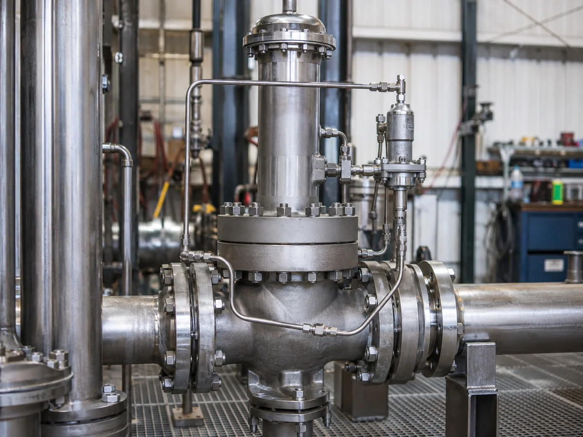
Pilot-Operated Safety Valve Troubleshooting
Pilot-operated safety valves can become unreliable in dirty, waxy, fouling or polymerizing service because the pilot circuit depends on small sensing paths, filters, restrictions, pilot seats and dome-pressure passages. A deposit does not need to block the main valve nozzle to create a serious pressure-protection problem.
If the pilot cannot sense pressure correctly, charge or vent the dome at the right time, or reseat cleanly, the main valve may open late, operate unstably, leak, or fail to reseat. The most important question is not whether the valve is called pilot-operated, but whether the selected pilot circuit can remain functional in the actual service.
This does not mean a pilot-operated safety valve is automatically unsuitable for every dirty service. It means the service must be reviewed for contaminant type, wax or polymer formation, temperature profile, pressure data, required relieving capacity, back pressure, installation and maintenance accessibility before quotation or replacement.
Quick Answer: Why Dirty Service Creates a Special Risk for Pilot-Operated Safety Valves
A pilot-operated safety valve uses a pilot system to control pressure above the main valve disc or piston. In clean service, this can support high operating pressure, tight seating and controlled opening behavior. In dirty, waxy or polymerizing service, the same control circuit can become the weak point.
The main risk is not only “dirt in the valve.” The engineering question is whether the pilot can still transmit, vent and restore control pressure with the timing required for the governing relief scenario.
The Main Valve May Be Clean While the Pilot Circuit Is Already Compromised
A common troubleshooting mistake is to inspect only the main valve seat, nozzle and outlet, then assume the valve is acceptable because the larger passage is not visibly blocked. In a pilot-operated design, the main valve and pilot circuit perform different tasks.
The main valve provides the relieving flow path. The pilot circuit decides when and how the main valve is allowed to open and reseat. If a sensing line or pilot restriction is partly blocked, the pilot may not see the actual vessel or line pressure quickly enough. If the dome vent path is restricted, the main valve may not open as expected. If the dome charging path is restricted after relief, the valve may reseat slowly or continue to leak.
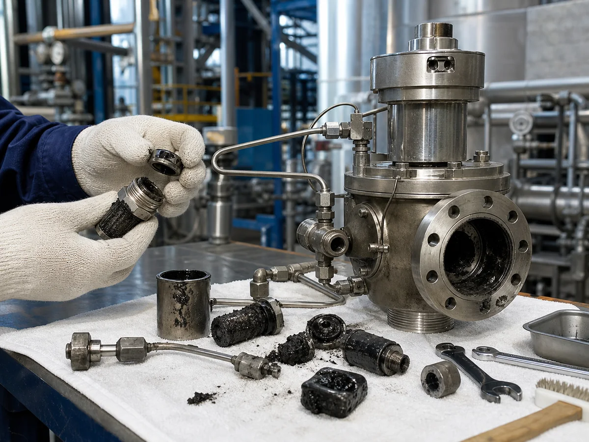
Simplified engineering illustration; not a manufacturing drawing or certified model section.
Failure chain: process contamination enters or forms inside a small passage → the passage becomes restricted, sticky or blocked → pressure transmission or dome venting changes → pilot response changes → main valve opening, stability or reseating becomes unreliable.
This is why pilot operated safety valves in dirty service must be reviewed as complete control systems, not as main valve bodies alone.
Pilot-Circuit Parts That Need Separate Review
| Pilot-Circuit Area | Dirty-Service Risk | Engineering Check |
|---|---|---|
| Sensing line | Blocked, partially restricted, cooled, waxed or filled with deposits | Routing, slope, length, isolation risk, heat loss and as-found deposits |
| Pilot inlet / restriction | Solids or sticky deposits slow pilot response | Cleanliness, filter condition and passage geometry against manufacturer design |
| Pilot seat | Particles or deposits prevent tight pilot seating | Seat surface, leakage history, cleaning record and compatible soft goods |
| Dome charging path | Slow dome repressurization after relief | Dome pressure restoration, deposits and pilot tubing condition |
| Dome vent / exhaust path | Main valve may open slowly or fail to reach expected opening behavior | Vent path cleanliness, vent routing and manufacturer-approved arrangement |
| Filter or strainer | Protects pilot passages but can become the restriction point | Inspection interval, element condition, pressure effect and maintenance access |
Not All Dirty Services Fail in the Same Way
Dirty particulate, waxy and polymerizing services should not be treated as one generic “dirty service” category. Each mechanism affects the pilot circuit differently, and each one changes the engineering decision.
| Service Mechanism | Typical Failure Location | What Changes the Decision |
|---|---|---|
| Particulate contamination | Filter, sensing line, pilot inlet, restriction, pilot seat | Particle loading, debris source, filter arrangement, startup cleanliness and maintenance access |
| Waxy or heavy hydrocarbon deposition | Cooler small-bore lines, stagnant tubing, low-flow pilot passages | Temperature profile, wax appearance behavior, shutdown condition, ambient temperature and heat loss |
| Polymerizing or reactive medium | Low-flow control passage, stagnant pocket, pilot seat or tubing | Residence time, chemistry, inhibitor dependence, temperature window and recurrence after cleaning |
| Unknown fouling behavior | Cannot be assumed | Do not finalize selection until medium, deposits and maintenance history are defined |
Dirty Particulate Service: How Solids Plug or Restrict the Control Circuit
Dirty particulate service may include rust, scale, catalyst fines, pipe debris, corrosion products, sand, process solids or carryover from upstream equipment. These particles may be intermittent rather than constant. A valve can pass an initial inspection and still become unreliable after startup, maintenance, line cleaning, catalyst changeout or upstream upset.
Sensing Lag
A partly restricted sensing line can delay the pressure signal reaching the pilot. The valve may appear acceptable in static inspection but respond too slowly during a real event.
Filter Loading
A pilot filter can protect downstream passages, but it becomes a maintenance item. If it loads with solids, it can become the next restriction point.
Dome-Pressure Error
Restricted charging or venting can make the main valve respond at the wrong time, open slowly, reseat late or leak after operation.
Partial restriction is often harder to diagnose than full blockage. A completely blocked line may be found during inspection. A partly restricted path may still pass some pressure, but not fast enough for stable protective action during a real relieving event.
Important boundary: filtration is not the same as dirty-service qualification. A filter can reduce solid particles upstream of the filter, but it cannot automatically prevent wax precipitation, polymer formation, sticky pilot-seat deposits, poor sensing-line routing or unsuitable temperature exposure.
Waxy and Heavy-Hydrocarbon Service: Deposition Can Be Temperature-Dependent
Waxy service is different from ordinary dirty service. The fluid may appear acceptable at normal operating temperature, then deposit wax when temperature drops in a small-bore sensing line, pilot tubing, external connection or stagnant volume.
The main process line may remain hot and flowing, while the pilot circuit sees lower velocity and different thermal conditions. This can create localized deposition even when the protected equipment itself does not appear heavily fouled. For heated, viscous or solidifying media, jacketed safety valves may be part of a wider service-condition review, but they are not an automatic substitute for a dirty-service POSV assessment.
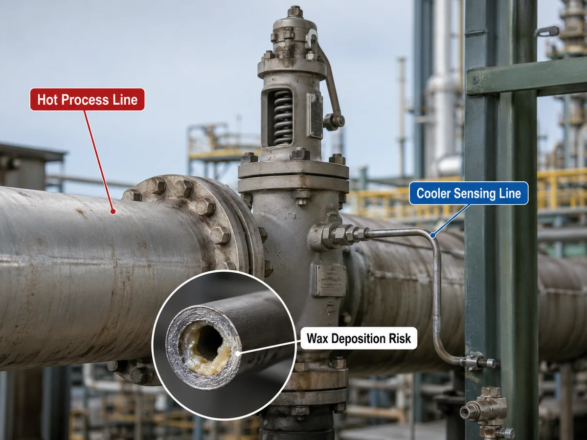
Conceptual engineering visual; temperature and wax behavior must be confirmed for the actual process fluid.
Important review points include normal operating temperature, relieving temperature, startup and shutdown temperature, minimum ambient temperature, heat loss from small-bore sensing lines, stagnant or dead-leg locations, line routing and slope, insulation or heat tracing requirements, and whether the service cools below a wax appearance or deposition condition.
Insulation or heat tracing should not be treated as an automatic fix. It must be reviewed against the process fluid, valve design, sensing arrangement, maintenance access and project safety requirements. In some cases, the most severe condition is not normal operation, but cold startup, shutdown, standby, winter operation or intermittent service.
Polymerizing Service: A Small Restriction Can Become a Growing Deposit
Polymerizing service requires an even more careful review because the deposit may form inside the pilot circuit rather than simply arrive as dirt from upstream piping. If the process medium can polymerize under certain temperature, residence time, oxygen exposure, catalyst, inhibitor, pressure or stagnant-flow conditions, small control passages become high-risk locations.
The most important difference is progression. A small amount of polymer buildup can change the pressure response. That change can increase residence time or reduce flushing. The restriction can then become worse over time.
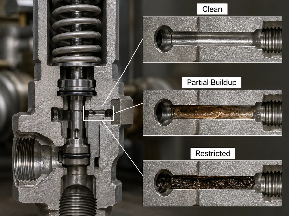
Simplified engineering illustration; actual polymerization risk depends on process chemistry and operating conditions.
A repeated clean-and-return maintenance pattern is a warning sign. If cleaning the pilot restores operation temporarily but the same symptoms return, the root cause may not be poor maintenance. It may be that the selected pilot arrangement creates or exposes a stagnant pocket where the fluid is not stable.
For polymerizing media, the RFQ or replacement review should not stop at valve size, set pressure and flange rating. It should include process composition, polymerization mechanism, inhibitor dependence, temperature window, stagnant-volume sensitivity, maintenance history and manufacturer evidence for the proposed pilot configuration.
What Failure Behavior Should Engineers Look For?
Dirty, waxy or polymerizing service can create several observable symptoms. These symptoms do not prove the root cause by themselves, but they indicate where inspection should begin.
- delayed opening response;
- inconsistent set behavior in service;
- unstable modulation or cycling where the pilot design is modulating;
- main valve opening slower than expected;
- incomplete dome venting;
- slow dome repressurization;
- leakage after operation;
- failure to reseat cleanly;
- increasing maintenance frequency;
- repeat fouling after cleaning;
- different behavior after shutdown, cold weather or process composition change.
| Observed Symptom | Possible Contamination Mechanism | What to Check First | Do Not Assume |
|---|---|---|---|
| Delayed response | Restricted sensing line or pilot inlet | Sensing path cleanliness, filter condition and routing | Set pressure is wrong |
| Slow main-valve opening | Restricted dome venting or pilot exhaust | Dome vent path, pilot exhaust and control passages | Main nozzle is undersized |
| Failure to reseat | Pilot seat contamination or slow dome repressurization | Pilot seat, dome charging path and deposits | Main seat alone is damaged |
| Intermittent leakage | Deposits on pilot seat or unstable pilot control | Pilot condition, soft goods and service history | Seat material alone is the cause |
| Cycling or instability | Combination of fouling, inlet loss, back pressure or sizing mismatch | Pilot circuit, inlet pressure loss, outlet system and valve sizing | Dirty service is the only cause |
| Increasing maintenance frequency | Progressive fouling, wax buildup or polymer formation | Deposit type, cleaning records and operating cycle | Shorter maintenance interval is a permanent solution |
| Problems after cold shutdown | Wax or heavy-fluid deposition in small-bore lines | Temperature profile, line routing and stagnant sections | The normal operating temperature proves suitability |
| Repeated fouling after cleaning | Deposit formation inside control path | Polymerization tendency, stagnant volume and process chemistry | Cleaning alone solves the problem |
Do Not Diagnose Pilot Fouling Until You Exclude System-Level Causes
Pilot fouling is only one possible explanation. A pressure-relief device is part of an installed system. Before deciding that dirty service has caused the failure, engineers should also review system-level causes.
Inlet Pressure Loss
Excessive pressure loss between the protected equipment and valve inlet can cause unstable operation. A restricted pilot circuit can create a similar symptom, so both must be checked. The safety valve installation guide should be reviewed when inlet connection, sensing location, piping support or discharge arrangement may affect valve behavior.
Outlet Back Pressure
Back pressure can change safety valve behavior depending on valve type, configuration and discharge system. Superimposed back pressure and built-up back pressure should be reviewed separately. A pilot-operated valve does not automatically solve every back-pressure condition, and dirty service does not remove the need to check discharge piping and outlet system resistance. For background, review back pressure and bellows.
Sizing and Operating Margin
An oversized valve, insufficient stable flow, poor operating margin or incorrect selected orifice can also cause unstable operation. Set pressure is not capacity. Connection size is not certified or documented relieving capacity. A valve may be physically connected to the system and still be wrong for the required relieving load. The capacity basis should be checked against safety valve sizing and certified relieving capacity.
Relief-System Review
If the symptom may involve discharge piping, depressuring, inlet loss, relief scenario definition or system interaction, the review should not stop at the valve body. The broader API 521 pressure relief systems context may be relevant when evaluating whether the installed system still supports the intended protective function.
Maintenance or Assembly Problems
After repair or cleaning, assembly error, damaged seals, wrong soft goods, blocked tubing, incorrect pilot setting or incomplete testing can create symptoms that look like process fouling. Review as-found and as-left records before making a replacement decision.
Unsafe Shortcuts to Avoid in Dirty-Service POSV Replacement
Do Not Replace by Flange Size Alone
Connection size proves the physical connection only. It does not prove selected orifice, coefficient, certified capacity, fluid basis or suitability for the governing relief scenario.
Do Not Treat Set Pressure as Capacity
Set pressure identifies the pressure setting. It does not prove the required relieving capacity, rated capacity, two-phase behavior or suitability after a process change.
Do Not Add a Filter Without Review
A filter can help, but it can also become the restriction. Filter size, access, element condition, maintenance interval and manufacturer approval matter.
Do Not Change Pilot Tubing Informally
Sensing location, tubing routing, vents, purge, heat tracing and clean-supply arrangements affect the protective function and should not be field-modified without engineering review.
Purge, Remote Sensing, Clean-Supply, Heating and Other Mitigation Options Need Design Review
There are possible mitigation strategies for some dirty, waxy or polymerizing services, but they must be reviewed as engineered arrangements, not field improvisations.
Clean or External Pilot Supply
This may reduce exposure of the pilot circuit to process contamination, but compatibility with the valve design and pressure-protection function must be confirmed.
Purge or Remote Sensing
A purge system must not compromise sensing accuracy, and a remote sensing line must still represent the protected equipment pressure.
Temperature Control
Heat tracing or insulation may be relevant for waxy service, but it must be reviewed against fluid behavior, safety requirements and maintenance access.
Other review directions may include manufacturer-approved pilot filters, alternate sensing-line routing, minimized stagnant volumes, service-specific pilot arrangements, accessible inspection points and defined maintenance evidence based on actual service history.
Do not modify a pilot circuit in the field without engineering approval. Unapproved changes to sensing lines, filters, vents, clean supply, purge flow or heating can compromise the protective function.
Manufacturer Evidence and Limits
Manufacturer documentation for pilot-operated relief valves commonly shows that service-specific accessories or configurations may exist for certain product families. Examples include remote pressure sensing, pilot filtering, clean media source arrangements, dirty-service options and other pilot-circuit modifications. This supports the need for manufacturer review, but it does not make filtration, purge, remote sensing or heating a universal solution for every dirty service.
- Emerson Anderson Greenwood pilot-operated relief valve documentation shows product-family options such as remote pressure sensing. These are product-specific options, not general approval for all services.
- Baker Hughes Consolidated 3900 POSRV documentation includes dirty-service / precipitation / viscous-fluid option context for a defined POSRV product family. This should be used as manufacturer-specific evidence, not as a ZOBAI model claim.
For ZOBAI RFQ review, this means the buyer should provide the actual process medium, phase, contaminants, temperature profile, pressure data, required capacity, back pressure, sensing arrangement and maintenance evidence. The final configuration must be confirmed against the selected valve series, manufacturer data, applicable code edition, project specification and local regulatory requirements.
When Should You Reconsider Using a Pilot-Operated Safety Valve?
A pilot-operated safety valve may still be suitable in some contaminated services if the contamination mechanism is understood and the manufacturer-approved configuration addresses the risk. It should be reconsidered when the service has a high probability of plugging, deposition, polymer growth or maintenance failure in the control circuit.
| Service Condition | POSV Review Direction | Main Concern |
|---|---|---|
| Clean gas or vapor | Normal POSV review | Standard pressure, capacity, back-pressure and material inputs |
| Occasional fine solids | Special pilot/filter review | Restriction and maintenance evidence |
| Heavy particulate loading | High-risk review | Rapid filter or passage fouling |
| Waxy hydrocarbon | Temperature and deposition review | Small-bore cold spots and stagnant sections |
| Polymerizing fluid | Specialist service review | Deposit growth inside low-flow control paths |
| Unknown contamination mechanism | Do not finalize selection | Insufficient service definition |
| Frequent repeat fouling | Reassess valve configuration | Cleaning may not solve root cause |
| Critical service with poor access | Strong reliability review | Inspection and maintenance may be impractical |
Final Selection Direction: Keep, Review, or Reconsider
Keep POSV Review Path
Use the normal POSV review route only when the medium is clean enough, the pilot circuit is compatible with the service, required capacity and back pressure are confirmed, and maintenance access is realistic.
Special POSV Review Required
Use this route for occasional solids, wax tendency, filter loading risk, sensing-line uncertainty or service history that shows intermittent fouling but not uncontrolled deposit growth.
Reconsider Configuration
Reconsider the pressure-relief configuration when the service has heavy solids, repeat wax blockage, polymer growth, unknown deposits, poor maintenance access or repeated failure after cleaning. Broader valve selection can then be reviewed through the safety valve selection guide.
Alternative configurations should be evaluated against the actual relief scenario, required relieving capacity, back pressure, material compatibility, installation and applicable code basis. They should not be selected only because the service is described as dirty.
Inspection and Maintenance Evidence That Should Be Reviewed
For an existing valve, the most useful evidence is usually the as-found condition. Before ordering a replacement, collect information that shows where the failure chain begins.
- photos of pilot filter condition;
- deposits found in sensing lines;
- pilot seat contamination;
- dome tubing condition;
- cleaning frequency;
- date and condition after the last maintenance event;
- as-found and as-left set pressure;
- seat-tightness test results where applicable;
- leakage history;
- operating temperature history;
- shutdown or cold-weather history;
- process composition changes;
- upstream maintenance or debris events;
- existing datasheet and nameplate;
- previous repair parts and soft goods;
- management-of-change records.
A set-pressure test alone does not prove that the installed valve is suitable for dirty service. Seat tightness, pilot response, capacity basis, installed piping and service contamination must be reviewed separately.
RFQ and Replacement Data for Dirty, Waxy, or Polymerizing Service
Before requesting a quotation or replacement recommendation, send enough data to define the protection duty and the contamination risk.
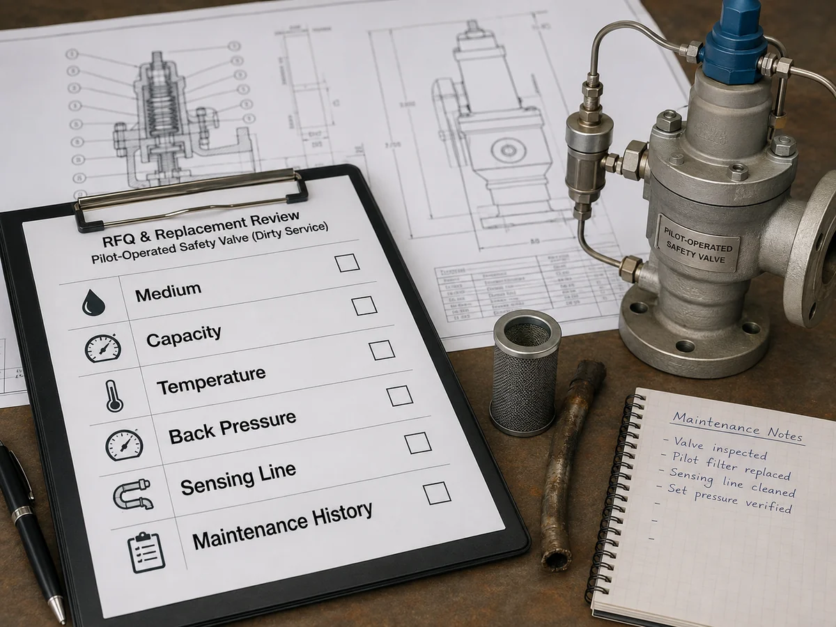
Checklist visual only; it does not replace project engineering review.
| Data Required | Why It Matters |
|---|---|
| Protected equipment | Confirms what must be protected |
| Governing relief scenario | Defines why the valve must relieve |
| Medium and composition | Identifies contamination, wax or polymer risks |
| Phase basis | Gas, vapor, liquid and two-phase duties cannot be interchanged |
| Solids or contamination description | Defines plugging and filter risk |
| Wax or deposition tendency | Determines temperature-related fouling risk |
| Polymerization tendency | Determines deposit-growth risk in stagnant passages |
| Operating pressure / MAWP / set pressure | Separates normal operation, protected equipment limit and valve setting |
| Required relieving capacity and capacity basis | Confirms the flow duty to be protected |
| Relieving temperature | Affects material, deposits and sizing basis |
| Superimposed and built-up back pressure | Affects valve behavior before and during discharge |
| Inlet, outlet and sensing-line arrangement | Helps evaluate inlet loss, discharge effects and contamination-prone geometry |
| Existing filter, purge or clean-supply arrangement | Shows current contamination-control strategy |
| Materials and soft goods | Confirms compatibility with medium and temperature |
| Existing nameplate, datasheet and maintenance history | Prevents replacement by appearance only |
| Applicable code and documents | Defines project acceptance basis |
The main selection risk is replacing the valve by appearance, flange size or nameplate set pressure alone. Connection size alone does not prove capacity, and set pressure alone does not prove the selected valve can protect the governing relief case.
For sizing-related review, see the ZOBAI guide to API 520 safety valve sizing.
Failure Investigation Workflow Before Replacement
- Confirm the protected equipment and governing relief scenario. Do not troubleshoot the valve separately from the system it protects.
- Collect as-found evidence. Photograph pilot filter, sensing line, deposits, tubing, pilot seat and maintenance findings before cleaning.
- Identify the contamination mechanism. Separate particulate solids, wax deposition, polymer growth, liquid carryover and unknown fouling.
- Check system effects. Review inlet loss, outlet back pressure, operating margin, valve sizing and discharge piping before blaming the pilot alone.
- Review manufacturer-approved arrangements. Confirm whether filter, purge, clean supply, remote sensing or heating is supported for the selected valve design.
- Recheck capacity and code basis. Required capacity, certified/documented capacity, medium phase and adopted standard edition must still be confirmed.
- Decide whether replacement by same type is acceptable. If the failure mechanism remains unresolved, repeating the same valve configuration may repeat the failure.
Composite Engineering Scenarios
The following scenarios are illustrative training examples. They are not ZOBAI customer cases and should not be treated as proof of product performance.
Composite Scenario 1: Particulate Fouling After Upstream Maintenance
A pilot-operated valve begins responding inconsistently after upstream equipment is opened for maintenance. The main valve seat appears acceptable, but debris is found in the sensing path and pilot filter. The likely failure chain is debris migration, partial pilot restriction and delayed pressure transmission.
The corrective action is not simply to reset the valve. The sensing path, pilot filter, pilot seat and upstream cleanliness should be reviewed. The prevention measure may include startup cleanliness control, filtration review and maintenance evidence requirements.
Composite Scenario 2: Waxy Hydrocarbon After Cold Shutdown
A valve operates acceptably during hot normal operation but becomes unreliable after cold shutdown. Inspection finds waxy deposits in a small-bore external sensing connection. The likely failure chain is temperature drop, wax deposition and restricted pressure communication.
The review should include minimum ambient temperature, shutdown condition, line routing, stagnant pockets and manufacturer-approved temperature-control options. Insulation alone should not be assumed to solve the problem.
Composite Scenario 3: Polymerizing Fluid With Repeat Cleaning
A valve returns to normal after pilot cleaning, but similar symptoms appear again after a period of operation. The failure chain may be polymer formation in a low-flow pilot passage or stagnant control volume.
Repeated cleaning may restore short-term operation without solving the root cause. The service chemistry, residence time, pilot arrangement and suitability of the valve configuration should be reviewed before selecting the same replacement design.
Standards and Engineering Boundary
Pilot-operated safety valves may be specified and reviewed under project-adopted pressure-relief standards and pressure equipment codes. ISO 4126-4 is a product standard for pilot-operated safety valves and should not be treated as an application-selection approval for every dirty, waxy or polymerizing service. ZOBAI also provides an internal overview of ISO 4126 safety valve standards for buyers who need a broader standards context. API 520 Part I is a sizing and selection reference for pressure-relieving devices in refinery service. API 521 addresses pressure-relieving and depressuring systems. ASME BPVC Section XIII is a reference for rules for overpressure protection.
The adopted edition, jurisdictional requirements, manufacturer data and project specification must be verified for each project. This article does not replace relief-system calculation, manufacturer review or local regulatory approval.
FAQ
Can pilot-operated safety valves be used in dirty service?
Sometimes, but not by assumption. Dirty service requires review of the contamination mechanism, pilot circuit, sensing path, filter or purge arrangement, maintenance access, temperature conditions and manufacturer-approved configuration.
Can a pilot filter prevent POSV failure?
A filter can reduce solid contamination entering the pilot circuit, but it can also become a restriction. It does not automatically prevent wax deposition, polymer formation, sticky pilot-seat deposits or poor sensing-line routing.
Why does wax build up in pilot sensing lines?
Wax may remain mobile in the hot process line but deposit when small-bore sensing lines or pilot tubing cool down. Low velocity, stagnant sections, cold shutdown and poor routing can increase deposition risk.
Why is polymerizing service difficult for a pilot-operated valve?
Polymerizing service can form deposits inside low-flow or stagnant control passages. Even a small buildup can change pilot response, dome venting or reseating behavior.
Can dirty service cause a pilot-operated valve to open late?
Yes. If the sensing line, pilot inlet, filter or control restriction is partly blocked, pressure may not reach the pilot correctly or quickly enough. The valve response can be delayed or unstable.
How can I tell whether instability is caused by pilot fouling or piping?
Check both. Inlet pressure loss, outlet back pressure, oversized valve selection, poor operating margin and discharge piping effects can also cause instability. Pilot contamination should be confirmed with inspection evidence.
When should another pressure-relief valve configuration be considered?
Consider another configuration when the service has heavy solids, recurring wax deposition, polymer formation, poor access for maintenance, unknown contamination behavior or repeated pilot fouling despite cleaning and manufacturer review.
Ask for an Engineering Review Before Replacing a Dirty-Service POSV
If your pilot-operated safety valve is used in dirty, waxy or polymerizing service, send the process conditions before selecting a replacement valve. A proper review should determine whether the pilot circuit can be engineered for the service, or whether another pressure-relief configuration should be evaluated.
Please include the protected equipment, governing relief scenario, medium and phase, contamination description, operating pressure, MAWP or design pressure, set pressure, required relieving capacity, relieving temperature, back pressure, inlet and outlet piping, sensing-line arrangement, materials, existing datasheet, nameplate and maintenance history.






Comments
Kesari Alloys
The emphasis on treating pilot-operated safety valves as complete control systems rather than just focusing on the main valve is crucial. The article rightly highlights how a partly restricted sensing line can lead to slow pressure response, which can be catastrophic during relief events. Have you observed specific case studies where inadequate pilot circuit assessment resulted in valve failures? It would be interesting to know how common this issue is across various industries.