Pilot-Operated Safety Valve Engineering Comparison Flowing and non-flowing pilot-operated safety valves differ mainly in the pilot circuit during stable relief. A flowing design normally maintains a controlled bleed or flow; a non-flowing design normally stops continuous pilot flow after the main valve reaches a stable relieving condition, although transient flow can still occur during actuation, …

Pilot-Operated Safety Valve Engineering Comparison
Flowing and non-flowing pilot-operated safety valves differ mainly in the pilot circuit during stable relief. A flowing design normally maintains a controlled bleed or flow; a non-flowing design normally stops continuous pilot flow after the main valve reaches a stable relieving condition, although transient flow can still occur during actuation, lift adjustment, reseating and dome recharge. The distinction matters when pilot exhaust, emissions, moisture, contamination, icing, back pressure or long-duration relief affect the specification. It does not define pop or modulating action, sensing location or relieving capacity. Set pressure and connection size also do not prove that the selected valve has adequate documented capacity. Before selection, confirm the protected equipment, relief scenario, medium and phase, operating pressure, MAWP or design pressure, set pressure, required capacity, relieving temperature, superimposed and built-up back pressure, sensing source, exhaust destination, materials and required documents. Send these conditions for an engineering review.
Flowing vs Non-Flowing Pilot-Operated Safety Valves: Quick Answer
Flowing or non-flowing describes process-medium behavior through the pilot circuit. A flowing pilot normally maintains a designed flow during the relevant stable-relief state; a non-flowing pilot normally stops continuous pilot flow at stable lift. Neither term defines main-valve action, sensing location, exhaust destination or relieving capacity.
A non-flowing pilot can still pass a transient volume while it actuates, changes dome pressure or repressurizes the dome. It should not be described as zero flow, zero emissions or maintenance-free.
Review the selected architecture within the full pilot operated safety valve system rather than treating pilot-flow classification as a complete specification.
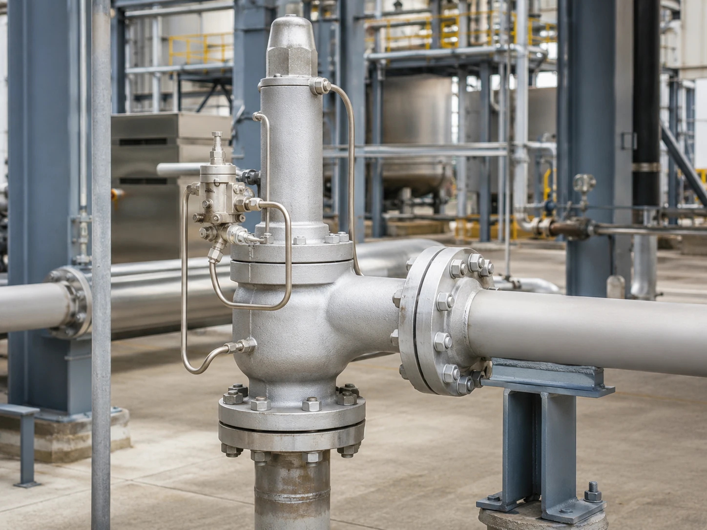
Realistic conceptual visualization. Final valve geometry, sensing, exhaust routing, pressure range and documented capacity must be confirmed against the selected model.
Selection boundary: Neither pilot type is universally better. Pilot architecture does not establish the required capacity, selected orifice, acceptable back pressure, material compatibility or code suitability. Those decisions require the governing relief scenario and manufacturer-specific documentation.
Preliminary Selection Matrix
This matrix is a screening tool, not a model recommendation. It identifies the questions that should be resolved before a flowing or non-flowing pilot is specified.
Scroll horizontally to review all columns.
| Service or Project Condition | Why It Matters | Flowing-Pilot Review | Non-Flowing-Pilot Review | Engineering Hold Point |
|---|---|---|---|---|
| Local atmospheric pilot exhaust is restricted | Pilot venting may be unacceptable for hazardous, valuable or regulated media. | Confirm sustained pilot flow and approved routing. | Confirm transient exhaust and the selected model’s stable condition. | Hold selection until exhaust destination and outlet-pressure effects are defined. |
| Relieving events may be prolonged | Long duration can increase pilot-medium loss and exhaust-system load. | Request operating-cycle and pilot-flow data. | Confirm when continuous flow stops and how lift is controlled. | Duration alone does not decide architecture; capacity and stability still govern. |
| Wet gas, low ambient temperature or hydrate risk | Restrictions, filters, sensing lines and exhaust paths can freeze or collect liquid. | Review expansion cooling, drainage, heating and temperature limits. | Review transient expansion, dome recharge and wet sensing lines. | Hold until moisture control and minimum temperature are confirmed. |
| Dirty, polymerizing or particulate-bearing medium | Small passages and seats can plug, stick or erode. | Assess continuous exposure of restrictions and filters. | Assess seats, transient paths, filtering and dome contamination. | A filter alone does not make the service acceptable. |
| Variable outlet pressure or common discharge header | Outlet pressure can change pilot exhaust and main-valve force balance. | Confirm how outlet pressure acts on the exhaust and dome circuit. | Confirm stable-relief control, reset and backflow behavior. | Separate superimposed and built-up back pressure. |
| Remote sensing is required | Sensing-line routing, pressure loss, pulsation, drainage and isolation can affect operation. | Confirm the remote signal is compatible with the selected pilot circuit. | Confirm dome control and transient response with the remote sensing arrangement. | Do not infer remote-sensing suitability from the pilot-flow classification. |
| Liquid, flashing or two-phase service is possible | Phase behavior affects capacity, pilot dynamics and discharge stability. | Require explicit manufacturer approval for the actual phase and relief case. | Require explicit manufacturer approval for the actual phase and relief case. | Flowing/non-flowing comparison alone is insufficient. |
RFQ hold point: Do not convert a preference such as “non-flowing required” into a final model selection until the relief load, phase, relieving temperature, back pressure, sensing source and exhaust destination are available.
How a Pilot-Operated Safety Valve Controls the Main Valve
Main Valve, Pilot and Dome Pressure
A typical system includes the main relieving valve, pilot, dome or control chamber, sensing path, tubing and pilot exhaust. Below set pressure, process pressure normally maintains dome pressure and the main valve’s closing force.
At set pressure, the pilot changes the dome-pressure path so inlet pressure can open the main valve. As pressure falls toward the pilot closing pressure, the dome is repressurized and the main valve reseats.
Sensing Pressure and Pilot Exhaust
Pressure may be sensed integrally or remotely. Pilot exhaust may go to atmosphere, the main outlet or another approved closed route; neither choice is determined by flowing or non-flowing classification.
Pilot Operation Does Not Replace Capacity Verification
Set-pressure response does not prove that the valve can pass the governing relief load. Confirm required capacity, selected orifice and documented capacity separately; connection size is not a capacity basis. See safety valve sizing and certified relieving capacity.
Required Capacity, Selected Valve and Evidence Are Different
The pilot architecture controls the main valve, but it does not replace the capacity-selection chain. Each item below answers a different engineering question.
Steam, air or gas, liquid and two-phase capacity values are not interchangeable. The selected capacity basis must match the actual relieving medium, phase, pressure, temperature, back pressure and applicable calculation method.
Scroll horizontally to review all columns.
| Item | What It Represents | Required Evidence | What It Does Not Prove |
|---|---|---|---|
| Required relieving capacity | Relief load from the governing overpressure scenario. | Calculation basis, fluid properties, phase, relieving pressure and temperature. | It does not select connection size or pilot type. |
| Required flow area | Calculated minimum effective area for the sizing basis. | Applicable method, coefficients, back pressure and fluid assumptions. | It does not prove a commercial orifice has sufficient documented capacity. |
| Selected orifice or valve design | Manufacturer geometry chosen to meet the required load. | Model datasheet, orifice designation and capacity documentation. | It does not prove temperature, material, exhaust or back-pressure suitability. |
| Documented or certified capacity | Published or documented performance under stated conditions. | Capacity table, certificate or calculation record required by the project. | It does not replace verification of the actual medium and relieving conditions. |
| Inlet and outlet connection size | The piping interface and flange or threaded connection. | General arrangement and connection specification. | Connection size alone does not prove relieving capacity. |
| Set-pressure test | The pressure response of the pilot and valve under the test procedure. | Calibrated test record and applicable acceptance criteria. | It does not independently prove field capacity, phase suitability or back-pressure performance. |
Engineering review note: A request containing only set pressure and connection size is incomplete. The required relieving capacity and its calculation basis are separate inputs and should be treated as mandatory hold points before model confirmation.
The Four Operating States Buyers Should Compare
Scroll horizontally to review all columns.
| Operating State | Flowing-Pilot Review | Non-Flowing-Pilot Review | Model-Specific Check |
|---|---|---|---|
| Normal closed operation | Determine whether a designed bleed or circulation path exists. | Determine whether the pilot circuit becomes static after dome pressurization. | Supply, dome and exhaust-seat arrangement. |
| Pilot actuation | Identify how the pilot flow path changes. | Identify the transient volume passing through the pilot. | Actuation sequence and dome depressurization path. |
| Steady main-valve relief | Confirm whether pilot flow continues. | Confirm that continuous pilot flow stops at stable lift. | Manufacturer operating schematic. |
| Reseating and dome repressurization | Confirm how dome pressure is rebuilt. | Confirm transient recharge flow and pilot reset. | Closing pressure, blowdown and back-pressure response. |
State 1: Normal Closed Operation
Below set pressure, confirm pilot-seat condition, sensing-line drainage, filter condition and possible dome leakage.
State 2: Pilot Actuation
At set pressure, the pilot restricts dome supply and reduces dome pressure. Some pilot flow normally occurs during this transition, including in a non-flowing design.
State 3: Steady Main-Valve Relief
This state separates the classifications: flowing designs maintain the intended pilot path, while non-flowing designs stop continuous pilot flow at stable lift.
State 4: Reseating and Dome Repressurization
As pressure falls, the pilot restores dome pressure. A non-flowing pilot can still pass transient recharge flow before the main valve closes.
What Is a Flowing Pilot?
A flowing pilot maintains a designed process-medium path during the relevant stable-relief state. The flow is small compared with main discharge but can matter for toxic, flammable, corrosive, valuable or moisture-bearing media. Baker Hughes’ operating fundamentals describe flowing and non-flowing pilots as one classification axis.
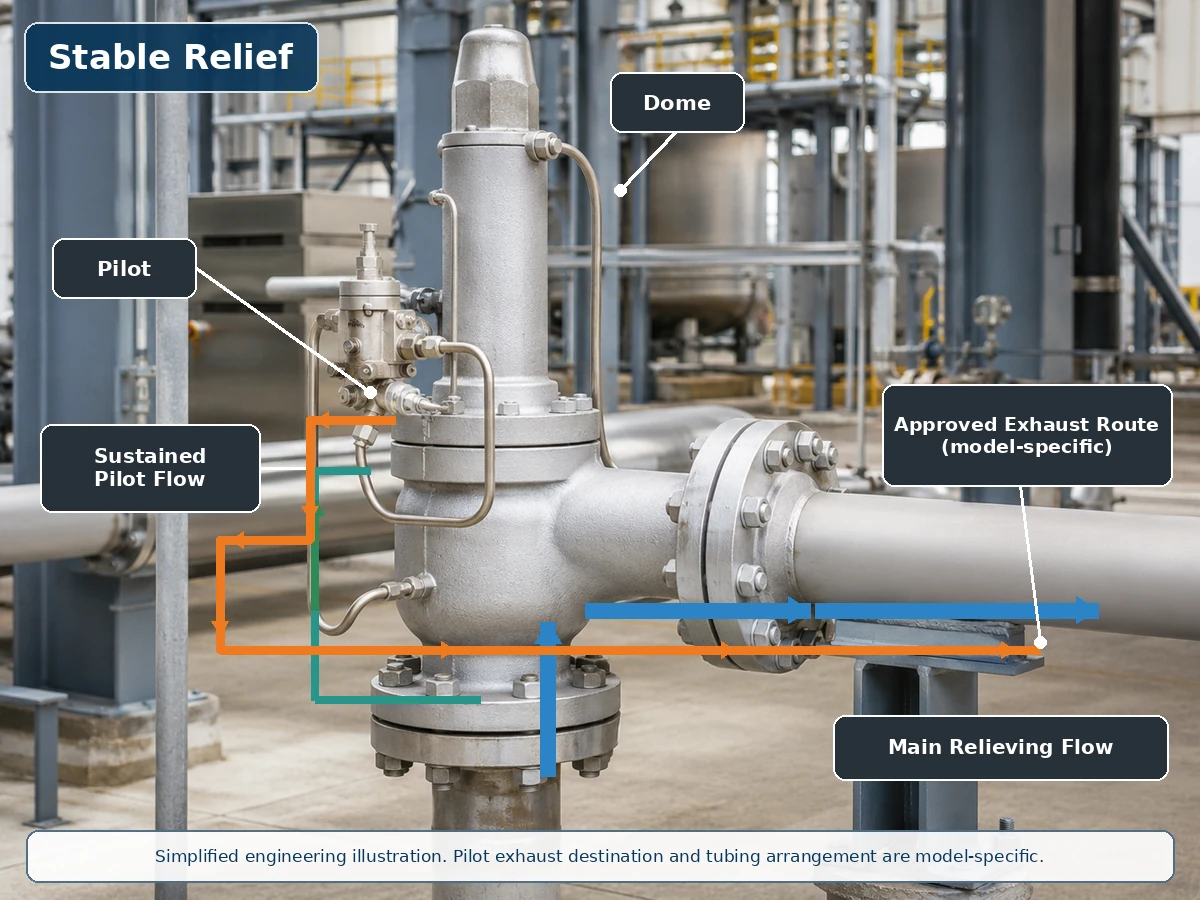
Simplified engineering illustration based on a realistic valve installation. Actual pilot supply, dome and exhaust paths are model-specific.
Flow Path During Main-Valve Relief
During relief, continued pilot flow may vent or regulate dome pressure. Confirm the pilot-flow basis, exhaust destination and service consequences rather than treating flow as an automatic disqualifier.
Pilot Exhaust and Dome Repressurization
Confirm whether exhaust goes to atmosphere, the outlet or another approved system, and whether outlet pressure, condensate, drainage, heating or winterization affect it.
What Is a Non-Flowing Pilot?
A non-flowing pilot reaches a stable condition in which continuous process-medium flow through the pilot stops while the main valve may remain open. Internal seats, feedback elements and dome-control details remain model-specific. Emerson’s Series 800 manual describes this stable-relief condition and also notes transient flow when the pilot changes lift.

Simplified engineering illustration. Non-flowing does not mean zero transient flow, zero leakage or zero emissions.
Transient Actuation and Dome Depressurization
At set pressure, the pilot reduces dome pressure; a small amount of dome or process medium can pass during this transition.
Stable Relief Without Continuous Pilot Flow
At stable lift, the pilot may isolate supply and exhaust so continuous pilot flow stops. This can reduce sustained medium consumption but does not prove zero leakage or eliminate contamination and freezing risks.
Reset and Dome Recharging
As pressure falls, the dome-supply path reopens and transient recharge flow occurs before the main valve closes.
Flowing vs Non-Flowing Pilot Comparison
Scroll horizontally to review all columns.
| Engineering Factor | Flowing Pilot | Non-Flowing Pilot | Selection Question |
|---|---|---|---|
| Stable pilot flow during relief | Normally maintained during the relevant control phase. | Normally absent at stable main-valve lift. | What does the selected operating schematic show? |
| Transient pilot flow | Present. | Present during pilot movement or dome control. | What volume and exhaust route apply? |
| Process-medium loss | May be higher through the pilot during sustained relief. | Usually lower through the pilot at stable relief. | Is the medium hazardous, valuable or controlled? |
| Atmospheric emissions | Possible if pilot exhaust is open to atmosphere. | Still possible during actuation if vented openly. | Where does pilot exhaust terminate? |
| Contaminant exposure | Depends on the continuous path, restrictions and filtering. | Depends on seats, passages, transient flow and filtering. | Is the medium suitable for the selected pilot? |
| Freezing and icing | Continuous expansion may be relevant. | Transient expansion and wet sensing lines can still freeze. | What minimum temperature and moisture condition apply? |
| Back-pressure exposure | Exhaust routing can affect pilot control. | Exhaust routing can also affect pilot control. | Is pilot exhaust connected to the outlet? |
| Pop or modulating action | Separate classification. | Separate classification. | Which main-valve action is required? |
| Relieving capacity | Not determined by pilot-flow type. | Not determined by pilot-flow type. | Is the documented capacity adequate for the relief case? |
Flowing vs Non-Flowing Is Not the Same as Pop vs Modulating
Pilot flow, main-valve action, sensing location and pilot-exhaust destination are independent decisions. A flowing pilot is not automatically pop-action, and a non-flowing pilot is not automatically modulating. Baker Hughes’ 2900-40 specification provides product-specific examples of both non-flowing pop-action and non-flowing modulating pilots; LESER’s POSV overview separately explains pop and modulating lift behavior.
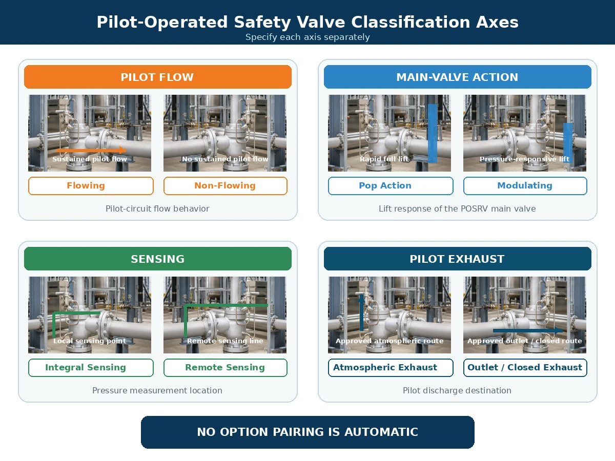
Simplified engineering comparison. Available combinations depend on the selected manufacturer and product series.
Scroll horizontally to review all columns.
| Classification Axis | Typical Options | What It Describes | What It Does Not Describe |
|---|---|---|---|
| Pilot flow | Flowing / non-flowing | Process-medium behavior through the pilot circuit. | Main-valve lift characteristic. |
| Main-valve action | Pop / modulating | Rapid full opening or pressure-responsive lift. | Whether pilot flow is continuous. |
| Sensing arrangement | Integral / remote | Where the pilot measures protected-system pressure. | Pilot-exhaust destination. |
| Exhaust arrangement | Atmosphere / outlet / approved closed route | Where pilot medium is discharged. | Main-valve action or relieving capacity. |
How Pilot Exhaust and Back Pressure Affect the Decision
Atmospheric Exhaust vs Outlet Exhaust
Atmospheric pilot exhaust may be unacceptable for toxic, flammable, corrosive, odorous, environmentally controlled or valuable media. Routing exhaust to the main-valve outlet can reduce local atmospheric release, but it can expose the pilot exhaust connection to outlet pressure.
Superimposed and Built-Up Back Pressure
Superimposed back pressure exists before the valve opens. Built-up back pressure develops because of relieving flow through the outlet system after opening. Either condition can affect main-valve force balance, pilot exhaust, dome-pressure reduction, lift, reseating and backflow. Review these effects with the ZOBAI guide to back pressure and bellows.
Scroll horizontally to review all columns.
| Condition | Data Required | Pilot-Circuit Question | Decision Boundary |
|---|---|---|---|
| Constant superimposed back pressure | Outlet pressure before opening. | Does it act on the exhaust, main valve or both? | Confirm the model limit and capacity basis. |
| Variable superimposed back pressure | Minimum, normal and maximum outlet-pressure profile. | Can variation change opening, lift, stability or reseating? | Do not approve from one average value. |
| Built-up back pressure | Discharge-system calculation at the governing relieving rate. | Can it restrict pilot exhaust or reduce main-valve performance? | Evaluate at required flow, not normal operation. |
| Pilot exhaust connected to the main outlet | Outlet pressure during opening, relief and reseating. | How are dome depressurization and reset affected? | Require the approved exhaust schematic. |
| Outlet pressure may exceed inlet or dome pressure | Credible reverse differential and operating sequence. | Is backflow prevention or another control required? | Do not assume the standard pilot arrangement prevents reverse flow. |
Backflow and Pilot-Circuit Protection
If outlet pressure exceeds inlet or dome pressure, discharge medium may enter the dome or pilot circuit or create an unintended main-valve opening force. Manufacturer-specific controls may include check devices, backflow prevention and approved exhaust arrangements.
Media, Temperature and Contamination Risks
Clean Gas and Vapor
Clean dry gas reduces some drainage and fouling concerns, but composition, expansion temperature, seals and exhaust classification still require review.
Condensation, Icing and Hydrates
Moisture, small passages and low points can create condensation, icing or hydrates. Non-flowing operation does not remove drainage and winterization requirements.
Dirty or Solidifying Media
Rust, scale, particles, wax and deposits can restrict pilot components. Filters must be suitable, accessible and maintained.
Temperature and Auxiliary Measures
Review all affected pilot and main-valve components, not only body material: wetted parts, nozzle, disc, guide, tubing, spring, seat/seal, diaphragm and any bellows used in the selected main-valve configuration. Remote mounting, heating, cooling or different materials may be required.
Scroll horizontally to review all columns.
| Medium or Condition | Pilot-System Risk | Items to Confirm | When Not to Proceed Without Review |
|---|---|---|---|
| Clean dry gas or vapor | Expansion cooling, seals and hazardous exhaust still matter. | Pilot body, tubing, seats, seals, minimum temperature and exhaust route. | When composition, relieving temperature or exhaust class is unknown. |
| Wet gas or condensable vapor | Condensate, icing, hydrates and blocked sensing paths. | Self-draining routing, low points, drains, heating and filter location. | When sensing and exhaust lines cannot be drained or winterized. |
| Dirty or particulate-bearing medium | Blocked restrictions, damaged seats, plugged filters and dome contamination. | Particle characteristics, filtration, passage size and maintenance access. | When suitability or a maintainable protection strategy is undocumented. |
| Corrosive medium | Attack of pilot body, tubing, wetted trim, seats and soft seals. | Materials, tubing, seat/seal compatibility and records. | When review is based only on main-valve body material. |
| Polymerizing, crystallizing or solidifying service | Sticking, blocked passages, deposits and impaired dome control. | Temperature control, purge/flushing, dead legs and maintenance basis. | When deposits can form in inaccessible passages. |
| High- or low-temperature service | Pilot spring, seats, seals, diaphragm, tubing and filters may see temperatures different from the main body. | Operating and relieving temperatures, ambient extremes, remote mounting, heating or cooling arrangements. | When only the main-valve body temperature rating has been checked. |
| Liquid, flashing or two-phase service | Dynamic response, capacity basis and pilot stability may differ from gas service. | Exact phase basis, relieving conditions and explicit manufacturer approval. | When the phase is assumed rather than calculated or confirmed. |
Installation Controls: What to Do and What to Avoid
The pilot architecture can only perform as intended when the main-valve inlet, outlet, sensing line, dome tubing and pilot exhaust are installed as an integrated pressure-protection system. For detailed inlet, outlet, support and sensing-line controls, use the safety valve installation guide.
Do
- Keep the main-valve inlet short and direct and evaluate inlet pressure loss for the governing relieving case.
- Support outlet piping independently and review discharge reaction force, thermal movement and header loads.
- Route remote sensing lines to minimize pressure loss, pulsation, liquid pockets and accidental isolation.
- Support pilot tubing and preserve the manufacturer’s required internal diameter, fittings and connection points.
- Route pilot exhaust to an approved safe destination and evaluate the pressure imposed on that route.
- Provide drainage, heating, insulation or environmental protection where the service and manufacturer instructions require them.
- Keep vents, drains, filters, test connections and maintenance joints accessible.
Do Not
- Do not connect the sensing line to an arbitrary point or assume the outlet pressure is the protected-system pressure.
- Do not add isolation valves to sensing or pilot lines without an approved locked or controlled arrangement.
- Do not reduce tubing size, add long unsupported runs or create low points without reviewing the response effect.
- Do not block, plug or combine a pilot vent or drain unless the selected design explicitly permits the arrangement.
- Do not let the main valve carry the weight or reaction load of heavy discharge piping.
- Do not treat heat tracing, purge or filters as universal remedies for an unsuitable medium.
- Do not change exhaust routing without checking back pressure, hazardous area and environmental requirements.
Installation hold point: Any change to sensing location, pilot tubing, exhaust routing, outlet header or isolation philosophy requires a manufacturer- and project-specific review before commissioning.
Common Failure Modes and Maintenance Checks
Scroll horizontally to review all columns.
| Observed Symptom | Possible Pilot-Circuit Cause | Other Possible Cause | Required Check |
|---|---|---|---|
| Main valve opens late | Blocked sensing line or pilot inlet. | Incorrect pressure measurement or set-pressure issue. | Verify sensing route and calibrated test data. |
| Main valve opens early | Pilot-seat leakage or incorrect pilot setting. | Pressure pulsation or unsuitable sensing point. | Inspect pilot and pressure source. |
| Main valve does not reach expected lift | Restricted pilot exhaust or inadequate dome depressurization. | Insufficient process flow or excessive back pressure. | Review the pilot exhaust and installed system. |
| Main valve cycles | Pilot instability or sensing-line pulsation. | Oversizing, inlet loss or variable back pressure. | Review the complete relief system. |
| Slow reseating | Restricted dome recharge path. | Main-valve friction or unsuitable blowdown. | Inspect pilot and main valve. |
| Pilot vent freezes | Wet medium and expansion cooling. | Ambient exposure or poor drainage. | Review moisture control and winterization. |
Do not diagnose from the symptom alone. A cycling, late-opening or low-lift valve can be caused by the pilot circuit, but it can also result from inlet pressure loss, valve oversizing, insufficient process flow, variable back pressure, main-valve friction or unsuitable sensing location. Preserve pressure records, pilot condition, tubing configuration and test evidence before changing the pilot setting.
Maintenance must follow an approved isolation, depressurization and testing procedure. Do not block pilot vents or drains, alter tubing without preserving the required design, or infer relieving capacity from a set-pressure test.
A Decision Workflow for Selecting the Pilot Architecture
1. Define the Relief Case
- Protected equipment and governing overpressure scenario; use the API 521 pressure relief systems guide where the project basis adopts API 521
- Operating pressure, MAWP or design pressure and set pressure
- Allowable overpressure and accumulation
- Required relieving capacity and calculation basis
- Relieving pressure, relieving temperature, medium and phase
2. Define Pilot Flow and Exhaust Requirements
- Whether sustained pilot flow is acceptable
- Atmospheric, outlet or closed exhaust requirement
- Pop or modulating action
- Integral or remote sensing
- Backflow prevention and field-test requirements
3. Review Service and Failure Risks
- Contamination, corrosion and solidification
- Condensation, icing and hydrate formation
- Vibration, pulsation and sensing-line arrangement
- Environmental exposure and maintenance access
4. Confirm the Manufacturer-Specific Design
- Pilot operating schematic and model datasheet
- Pressure, temperature, phase and back-pressure limits
- Materials, seals, filters, heaters and drains
- Documented capacity and required project documents
When This Comparison Is Not Enough
Do not select a valve from the flowing/non-flowing comparison alone when any of the following remains unresolved:
- The protected equipment or governing relief scenario has not been identified.
- The required relieving capacity, relieving pressure, relieving temperature or phase basis is missing.
- Superimposed or built-up back pressure is variable, unknown or affected by a common header.
- The medium can freeze, polymerize, crystallize, corrode, foul or carry solids.
- Remote sensing, closed pilot exhaust, backflow prevention or field testing is required.
- The replacement valve’s original pilot schematic, exhaust routing or sensing source is unavailable.
- The selected manufacturer has not confirmed the service, materials, pilot action and accessories.
Decision rule: When a missing input can change capacity, pilot stability, exhaust safety, material compatibility or code acceptance, record it as “To Be Confirmed” rather than converting it into an assumed fact.
Composite Engineering Scenarios
The following scenarios are composite training examples. They do not represent named customers, verified incidents or completed ZOBAI projects.
Clean High-Pressure Gas with Restricted Atmospheric Emissions
Observed issue: An RFQ specifies “non-flowing required” only because local atmospheric emissions are restricted. Engineering cause: The request treats stable pilot flow as if it were the only possible release path. Correction: Compare transient pilot exhaust, stable pilot flow, main-valve discharge, exhaust routing, back pressure and documented capacity. Prevention: Require the selected pilot schematic and an approved exhaust destination before model approval.
Wet Gas with Condensation and Freezing Risk
Observed issue: A wet-gas pilot responds slowly or becomes unstable during low ambient temperature. Engineering cause: Moisture collects in sensing or exhaust low points and freezes during pressure reduction. Correction: Restore self-draining routing and apply the manufacturer-approved drainage, heating or winterization arrangement. Prevention: Confirm minimum temperature, moisture condition, line routing, filters and maintenance access during design review.
Replacement Valve with Unconfirmed Pilot Exhaust Routing
Observed issue: A replacement POSRV matches flange sizes and set pressure but does not reproduce the original operating behavior. Engineering cause: The original pilot type, sensing source, exhaust route, capacity basis or back-pressure condition was not verified. Correction: Reconstruct the relief basis and compare the complete operating schematic and documented capacity. Prevention: Control replacements through management of change, approved drawings, test records, nameplate data and traceability.
Replacement Verification Workflow
A pilot-operated safety valve should not be replaced by matching appearance, inlet size, outlet size and set pressure alone.
Reconstruct the pressure-protection basis
Confirm the protected equipment, governing relief scenario, MAWP or design pressure, set pressure, allowable overpressure, required capacity and relieving conditions.
Identify the original pilot architecture
Obtain the original datasheet, nameplate, operating schematic and maintenance instructions. Confirm flowing or non-flowing, pop or modulating, sensing source and exhaust route.
Verify the installed connections
Trace the pilot supply, dome line, sensing line, exhaust, drains, filters, heaters, test connections and any backflow-prevention devices.
Compare real service conditions
Review medium, phase, contamination, operating and relieving temperatures, superimposed and built-up back pressure, ambient conditions and hazardous exhaust requirements.
Verify capacity and pressure response separately
Match required capacity to the documented capacity of the proposed valve and confirm set pressure, blowdown and action type against the project basis.
Approve installation differences
Do not change the sensing point, tubing, pilot exhaust, outlet arrangement, materials or accessories without documented review.
Define testing and release evidence
Agree on set-pressure testing, seat tightness, functional checks, material records, capacity evidence, drawings, manuals and inspection release before shipment or commissioning.
What Buyers Should Put on the Datasheet and RFQ
Specifying only “pilot-operated safety valve,” inlet size and set pressure is not enough. The supplier needs complete process, relief, pilot-circuit and document requirements.
Common RFQ gap: Requests often identify “pilot operated,” set pressure and connection size but omit the relief scenario, required capacity, relieving temperature, back pressure, sensing source and pilot-exhaust destination. These omissions should stop model confirmation rather than be filled by assumption.
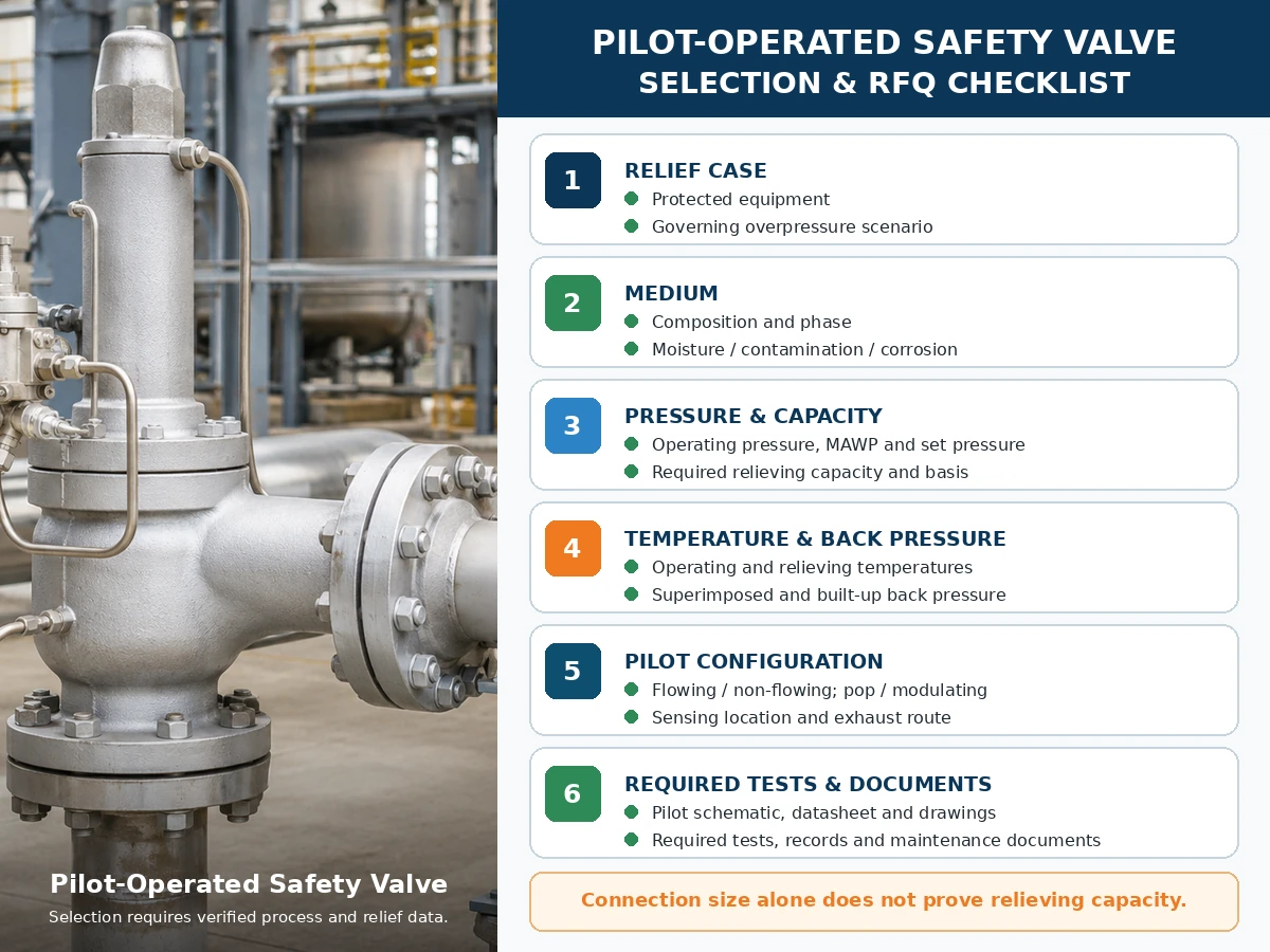
Engineering checklist only. Final model selection depends on verified process data, manufacturer information, applicable standards and project review.
Scroll horizontally to review all columns.
| Required Input | Why It Matters | Status |
|---|---|---|
| Protected equipment and governing relief scenario | Defines the pressure-protection duty and required load. | To be confirmed |
| Medium, composition and phase | Affects pilot, seals, exhaust handling and capacity basis. | To be confirmed |
| Operating pressure, MAWP/design pressure and set pressure | Defines operating margin and pressure boundary. | To be confirmed |
| Allowable overpressure and accumulation | Affects sizing and the applicable relief basis. | To be confirmed |
| Required relieving capacity and calculation basis | Determines the required documented valve capacity. | To be confirmed |
| Operating and relieving temperatures | Controls materials, seals, pilot arrangement and capacity basis. | To be confirmed |
| Superimposed and built-up back pressure | Affects main-valve and pilot-exhaust behavior. | To be confirmed |
| Flowing/non-flowing, pop/modulating, sensing and exhaust | Defines four separate pilot-system decisions. | To be confirmed |
| Materials, filtering, heating, drainage and maintenance access | Addresses service compatibility and failure controls. | To be confirmed |
| Applicable code, testing and documents | Defines the project evidence package. | To be confirmed |
Test and Document Matrix
Testing and documentation should show different parts of the pressure-protection evidence chain. One test report should not be used to claim results it does not establish.
Scroll horizontally to review all columns.
| Test or Document | What It Can Support | What It Does Not Prove by Itself | RFQ Check |
|---|---|---|---|
| Pilot or assembled-valve set-pressure test | Opening-pressure response under the stated procedure. | Capacity, field back-pressure response or process compatibility. | Specify medium, procedure, acceptance basis and report format. |
| Seat-tightness test / API 527 seat tightness test guidance where applicable | Leakage under the stated conditions and criteria. | Zero leakage in all services or operating conditions. | Specify method, test pressure, medium and acceptance criteria. |
| Functional pilot/main-valve test | Pilot actuation, dome control, main-valve movement and reset. | Full field capacity or untested discharge-header performance. | Confirm architecture, action type and included accessories. |
| Capacity table, certificate or calculation record | Documented relieving performance for the selected design. | Suitability for a different phase, temperature, back pressure or medium. | Match model, orifice, fluid basis and required evidence. |
| General arrangement and pilot operating schematic | Connections, flow paths, sensing, exhaust and accessories. | Material compatibility or capacity unless separately documented. | Require the drawing revision used for manufacture and installation. |
| Material records | Specified material identity for listed pressure-retaining and wetted components. | Corrosion suitability without a service-specific material review. | Define which components and traceability level are required. |
| Datasheet, nameplate and inspection release | Configuration, set pressure, model identification and agreed inspection status. | A complete relief calculation or universal certification. | Check consistency across the purchase order, drawing, test reports and final nameplate. |
| Installation and maintenance instructions | Approved tubing, sensing, exhaust, testing, maintenance and spare-parts guidance. | Project approval when the installed arrangement differs from the instructions. | Include the exact product-series revision in the document package. |
Repair and reset records: Where required by the applicable repair program or project specification, retain as-found and as-left set-pressure and seat-tightness data, replacement-parts records, resealing or nameplate controls, traceability and management-of-change approval. API 527 seat tightness guidance does not replace sizing or documented-capacity verification.
Standards and Source Notes
Manufacturer-specific operating evidence is linked beside the relevant flowing, non-flowing and pop/modulating statements above. Those documents support only the identified product families and must not be treated as universal POSRV performance data.
- API 520 Part I, 10th Edition — official API sizing and selection publication notice.
- API 520 Part II, 7th Edition — official API installation publication notice.
- ASME BPVC Section XIII, 2025 Edition — rules for overpressure protection.
- ISO 4126-4:2013 — pilot-operated safety valves; ISO lists the publication as reviewed and confirmed in 2025.
These references have different scopes. Confirm the project-adopted edition, protected-equipment code, jurisdiction, manufacturer/model scope and required documentation. A standard name is not proof that every ZOBAI model carries every certification.
Frequently Asked Questions
What is the difference between a flowing and non-flowing pilot-operated safety valve?
A flowing pilot maintains a designed pilot path during the relevant stable-relief state. A non-flowing pilot stops continuous pilot flow at a stable main-valve condition, although transient flow can occur during actuation and dome recharge.
Does a non-flowing pilot mean no process medium ever passes through the pilot?
No. Medium can pass while the pilot actuates, changes dome pressure or repressurizes the dome. Non-flowing refers to the stable condition, not every instant.
Is a non-flowing pilot always better than a flowing pilot?
No. Suitability depends on the medium, exhaust route, temperature, contamination, back pressure, required capacity, action type and selected manufacturer design.
Is flowing vs non-flowing the same as pop-action vs modulating?
No. Flowing or non-flowing describes pilot-circuit flow. Pop or modulating describes main-valve lift response. Specify them separately.
Where does the pilot exhaust go?
Depending on the design, pilot exhaust may go to atmosphere, the main outlet or another approved closed route. Confirm the schematic and back-pressure effect.
Which pilot type is better for hazardous or valuable process media?
A non-flowing design may reduce sustained pilot-medium loss, but transient exhaust, main discharge, leakage criteria, routing and model suitability still require review.
Can a non-flowing pilot still experience freezing or contamination?
Yes. Sensing lines, filters, restrictions, dome passages and exhausts can collect moisture, freeze or foul. Drainage, filtration and winterization remain service-specific.
What information is required before selecting the pilot architecture?
Provide the protected equipment, relief scenario, medium and phase, pressure data, required capacity, relieving temperature, back pressure, sensing, exhaust, piping, materials, action type and required documents.
Standards and Engineering Limitation
API 520 Part I addresses sizing and selection, while API 520 Part II addresses installation within their stated scopes. ASME BPVC Section XIII provides an overpressure-protection framework. ISO 4126-4 addresses pilot-operated safety valves as a product standard; it is not an application code for the protected system. Verify the edition adopted by the project, the applicable equipment code, jurisdiction and manufacturer-specific product data.
Final selection depends on the protected equipment, governing relief scenario, actual medium and phase, operating pressure, MAWP or design pressure, set pressure, required and documented relieving capacity, relieving temperature, superimposed and built-up back pressure, inlet and outlet piping, all affected materials and sealing components, pilot configuration, the adopted standard edition, project specification and applicable local regulatory requirements.
Request a Pilot-Operated Safety Valve Engineering Review
The final choice between flowing and non-flowing pilot-operated safety valves should follow the actual relief scenario, required capacity, medium and phase, relieving temperature, back pressure, sensing and exhaust arrangement, materials, piping and required documentation. Send those inputs before requesting a model recommendation.