Technischer Vergleich von pilotgesteuerten Sicherheitsventilen: Strömende und nichtströmende pilotgesteuerte Sicherheitsventile unterscheiden sich hauptsächlich im Pilotkreis während des stabilen Abblasens. Ein strömendes Design hält normalerweise einen kontrollierten Abfluss oder Durchfluss aufrecht; ein nichtströmendes Design stoppt normalerweise den kontinuierlichen Pilotstrom, nachdem das Hauptventil einen stabilen Abblasezustand erreicht hat, obwohl während der Betätigung, der Hubverstellung, des erneuten Sitzens und der Domaufladung vorübergehende Strömungen auftreten können, …

Technischer Vergleich von pilotgesteuerten Sicherheitsventilen
Strömende und nichtströmende pilotgesteuerte Sicherheitsventile unterscheiden sich hauptsächlich im Pilotkreis während des stabilen Abblasens. Ein strömendes Design hält normalerweise einen kontrollierten Abfluss oder Durchfluss aufrecht; ein nichtströmendes Design stoppt normalerweise den kontinuierlichen Pilotstrom, nachdem das Hauptventil einen stabilen Abblasezustand erreicht hat, obwohl während der Betätigung, der Hubverstellung, des erneuten Sitzens und der Domaufladung vorübergehende Strömungen auftreten können. Der Unterschied ist wichtig, wenn Pilotabgas, Emissionen, Feuchtigkeit, Verunreinigungen, Vereisung, Gegendruck oder langandauernde Entlastung die Spezifikation beeinflussen. Er definiert nicht die Pop- oder Modulationswirkung, die Messstelle oder die Entlastungskapazität. Ansprechdruck und Anschlussgröße beweisen ebenfalls nicht, dass das ausgewählte Ventil eine ausreichende dokumentierte Kapazität hat. Vor der Auswahl bestätigen Sie die geschützte Ausrüstung, das Entlastungsszenario, das Medium und die Phase, den Betriebsdruck, MAWP oder Auslegungsdruck, den Ansprechdruck, die erforderliche Kapazität, die Entlastungstemperatur, den überlagerten und aufgebauten Gegendruck, die Messquelle, den Abgasbestimmungsort, die Materialien und die erforderlichen Dokumente. Senden Sie diese Bedingungen für eine technische Überprüfung.
Strömende vs. nicht strömende pilotgesteuerte Sicherheitsventile: Kurzantwort
Strömend oder nicht strömend beschreibt das Verhalten des Prozessmediums im Pilotkreis. Ein strömender Pilot hält normalerweise einen konstruktionsgemäßen Durchfluss während des relevanten stabilen Entlastungszustands aufrecht; ein nicht strömender Pilot stoppt normalerweise den kontinuierlichen Pilotdurchfluss bei stabilem Hub. Keiner der Begriffe definiert die Hauptventilwirkung, die Messstelle, den Austrittsweg oder die Entlastungskapazität.
Ein nicht strömender Pilot kann während der Betätigung, der Änderung des Domdrucks oder der Wiederbefüllung des Doms ein transienten Volumen durchlassen. Er sollte nicht als null Durchfluss, null Emissionen oder wartungsfrei beschrieben werden.
Überprüfen Sie die gewählte Architektur im gesamten Pilotgesteuertes Sicherheitsventil System, anstatt die Pilot-Durchflussklassifizierung als vollständige Spezifikation zu betrachten.
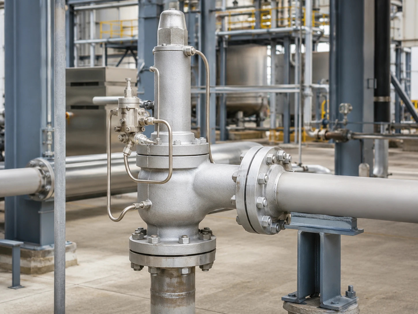
Realistische konzeptionelle Darstellung. Die endgültige Ventilgeometrie, Messung, Austrittsführung, Druckbereich und dokumentierte Kapazität müssen gegen das ausgewählte Modell bestätigt werden.
Auswahlgrenze: Kein Pilottyp ist grundsätzlich besser. Die Pilotarchitektur bestimmt nicht die erforderliche Kapazität, die gewählte Öffnung, den zulässigen Gegendruck, die Materialverträglichkeit oder die Code-Konformität. Diese Entscheidungen erfordern das maßgebliche Entlastungsszenario und die herstellerspezifische Dokumentation.
Vorläufige Auswahlmatrix
Diese Matrix ist ein Screening-Werkzeug, keine Modellempfehlung. Sie identifiziert die Fragen, die geklärt werden sollten, bevor ein strömender oder nicht strömender Pilot spezifiziert wird.
Scrollen Sie horizontal, um alle Spalten zu sehen.
| Betriebs- oder Projektbedingung | Warum es wichtig ist | Strömungs-Pilot-Überprüfung | Nicht-Strömungs-Pilot-Überprüfung | Technischer Haltepunkt |
|---|---|---|---|---|
| Lokaler atmosphärischer Pilotabgas ist eingeschränkt | Pilotentlüftung kann für gefährliche, wertvolle oder regulierte Medien ungeeignet sein. | Bestätigen Sie den anhaltenden Pilotstrom und die genehmigte Ableitung. | Bestätigen Sie den transienten Abgas und den stabilen Zustand des ausgewählten Modells. | Auswahl zurückstellen, bis Abgasziel und Auslassdruckeffekte definiert sind. |
| Ablassereignisse können verlängert sein | Lange Dauer kann den Pilotmedienverlust und die Abgasanlagenlast erhöhen. | Betriebszyklus- und Pilotstromdaten anfordern. | Bestätigen Sie, wann der kontinuierliche Strom stoppt und wie der Hub gesteuert wird. | Die Dauer allein entscheidet nicht über die Architektur; Kapazität und Stabilität sind weiterhin maßgeblich. |
| Nassgas, niedrige Umgebungstemperatur oder Hydratrisiko | Einschränkungen, Filter, Messleitungen und Abgaswege können einfrieren oder Flüssigkeit ansammeln. | Kühlung durch Expansion, Entwässerung, Beheizung und Temperaturgrenzen prüfen. | Transiente Expansion, Nachfüllen der Dome und nasse Messleitungen prüfen. | Warten, bis Feuchtigkeitskontrolle und Mindesttemperatur bestätigt sind. |
| Verschmutzendes, polymerisierendes oder partikelhaltiges Medium | Kleine Durchgänge und Sitze können verstopfen, festkleben oder erodieren. | Dauerhafte Belastung von Einschränkungen und Filtern bewerten. | Sitze, transiente Pfade, Filterung und Kontamination der Dome bewerten. | Ein Filter allein macht den Betrieb nicht akzeptabel. |
| Variabler Austrittsdruck oder gemeinsame Abgasleitung | Der Austrittsdruck kann die Pilotabblasung und das Kräftegleichgewicht des Hauptventils verändern. | Bestätigen Sie, wie der Austrittsdruck auf den Abblas- und Dome-Kreis wirkt. | Stabiles Abblasen, Rückstellung und Rückflussverhalten bestätigen. | Überlagerten und aufgebauten Gegendruck getrennt betrachten. |
| Fernmessung ist erforderlich | Leitungsführung der Messleitung, Druckverlust, Pulsation, Entwässerung und Absperrung können den Betrieb beeinflussen. | Bestätigen, dass das Fernsignal mit dem gewählten Pilotkreis kompatibel ist. | Domsteuerung und Übergangsverhalten bei Fernmessanordnung bestätigen. | Die Eignung für Fernmessung nicht aus der Pilotstrom-Klassifizierung ableiten. |
| Flüssigkeits-, Verdampfungs- oder Zweiphasenbetrieb ist möglich | Das Phasenverhalten beeinflusst Kapazität, Pilotdynamik und Abblasstabilität. | Ausdrückliche Herstellerfreigabe für die tatsächliche Phase und den Entlastungsfall erforderlich. | Ausdrückliche Herstellerfreigabe für die tatsächliche Phase und den Entlastungsfall erforderlich. | Der Vergleich von durchströmendem/nicht durchströmendem Zustand allein ist nicht ausreichend. |
Angebotsanfrage-Haltepunkt: Eine Präferenz wie “kein Durchfluss erforderlich” sollte erst dann in eine endgültige Modellauswahl umgesetzt werden, wenn Entlastungslast, Phase, Entlastungstemperatur, Gegendruck, Messstelle und Abgasweg bekannt sind.
So steuert ein pilotgesteuertes Sicherheitsventil das Hauptventil
Hauptventil, Pilot und Domdruck
Ein typisches System umfasst das Hauptentlastungsventil, den Piloten, den Dom bzw. die Steuerkammer, den Messpfad, die Rohrleitungen und den Pilotabgas. Unterhalb des Ansprechdrucks hält der Prozessdruck normalerweise den Domdruck und die Schließkraft des Hauptventils aufrecht.
Beim Ansprechdruck ändert der Pilot den Domdruckpfad, sodass der Einlassdruck das Hauptventil öffnen kann. Wenn der Druck in Richtung des Pilot-Schließdrucks fällt, wird der Dom wieder mit Druck beaufschlagt und das Hauptventil setzt wieder auf.
Messdruck und Pilotabgas
Der Druck kann integriert oder fernmessend erfasst werden. Das Pilotabgas kann zur Atmosphäre, zum Hauptauslass oder zu einem anderen zugelassenen geschlossenen Weg geleitet werden; keine der beiden Optionen wird durch die Klassifizierung „strömend“ oder „nicht strömend“ bestimmt.
Pilotbetrieb ersetzt keine Kapazitätsprüfung
Die Ansprechdruckreaktion beweist nicht, dass das Ventil die maßgebliche Entlastungslast durchlassen kann. Bestätigen Sie die erforderliche Kapazität, die ausgewählte Öffnung und die dokumentierte Kapazität separat; die Anschlussgröße ist keine Kapazitätsbasis. Siehe Sicherheitsventil-Auslegung und zertifizierter Abblaseleistung.
Erforderliche Kapazität, ausgewähltes Ventil und Nachweis sind unterschiedlich
Die Pilotarchitektur steuert das Hauptventil, ersetzt jedoch nicht die Kapazitätsauswahlkette. Jeder Punkt unten beantwortet eine andere technische Frage.
Dampf-, Luft- oder Gas-, Flüssigkeits- und Zweiphasen-Kapazitätswerte sind nicht austauschbar. Die gewählte Kapazitätsbasis muss dem tatsächlichen Entlastungsmedium, der Phase, dem Druck, der Temperatur, dem Gegendruck und der anwendbaren Berechnungsmethode entsprechen.
Scrollen Sie horizontal, um alle Spalten zu sehen.
| Artikel | Was er darstellt | Erforderliche Nachweise | Was es nicht beweist |
|---|---|---|---|
| Erforderliche Abblaseleistung | Entlastungslast aus dem maßgebenden Überdruckszenario. | Berechnungsgrundlage, Fluideigenschaften, Phase, Entlastungsdruck und -temperatur. | Er wählt weder Anschlussgröße noch Pilottyp aus. |
| Erforderliche Durchflussfläche | Berechnete Mindestfläche für die Auslegungsbasis. | Anwendbare Methode, Beiwerte, Gegendruck und Fluidannahmen. | Er belegt nicht, dass eine handelsübliche Öffnung eine ausreichende dokumentierte Kapazität aufweist. |
| Gewählte Öffnung oder Ventilbauart | Vom Hersteller gewählte Geometrie zur Erfüllung der geforderten Last. | Modell-Datenblatt, Öffnungsbezeichnung und Kapazitätsdokumentation. | Sie belegt nicht die Eignung hinsichtlich Temperatur, Werkstoff, Abblasung oder Gegendruck. |
| Dokumentierte oder zertifizierte Kapazität | Veröffentlichte oder dokumentierte Leistung unter angegebenen Bedingungen. | Leistungstabelle, Zertifikat oder Berechnungsnachweis, die vom Projekt gefordert werden. | Es ersetzt nicht die Überprüfung des tatsächlichen Mediums und der Entlastungsbedingungen. |
| Anschlussgrößen für Einlass und Auslass | Die Rohrleitungsschnittstelle und der Flansch- oder Gewindeanschluss. | Allgemeine Anordnung und Anschlussspezifikation. | Die Anschlussgröße allein beweist nicht die Entlastungskapazität. |
| Ansprechdruckprüfung | Das Druckverhalten des Piloten und des Ventils unter dem Prüfverfahren. | Kalibrierter Prüfbericht und anwendbare Akzeptanzkriterien. | Es beweist nicht unabhängig die Feldkapazität, Phaseneignung oder Gegendruckleistung. |
Hinweis zur technischen Überprüfung: Eine Anfrage, die nur Ansprechdruck und Anschlussgröße enthält, ist unvollständig. Die erforderliche Entlastungskapazität und ihre Berechnungsgrundlage sind separate Eingaben und sollten als verbindliche Haltepunkte vor der Modellbestätigung behandelt werden.
Die vier Betriebszustände, die Käufer vergleichen sollten
Scrollen Sie horizontal, um alle Spalten zu sehen.
| Betriebszustand | Strömungs-Pilot-Überprüfung | Nicht-Strömungs-Pilot-Überprüfung | Modellspezifische Prüfung |
|---|---|---|---|
| Normal geschlossener Betrieb | Prüfen, ob ein vorgesehener Entlastungs- oder Umwälzpfad vorhanden ist. | Ermitteln, ob der Pilotkreis nach der Dom-Druckbeaufschlagung statisch wird. | Anordnung von Zulauf, Dom und Auslasssitz. |
| Pilotbetätigung | Ermitteln, wie sich der Pilotströmungspfad ändert. | Ermitteln des transienten Volumens, das durch den Pilot strömt. | Betätigungssequenz und Dom-Druckentlastungspfad. |
| Stationäre Hauptventil-Entlastung | Bestätigen, ob der Pilotstrom weiterläuft. | Bestätigen, dass der kontinuierliche Pilotstrom bei stabilem Hub stoppt. | Betriebsschema des Herstellers. |
| Wiedereinsetzen und Wiederaufbau des Domdrucks | Bestätigen, wie der Domdruck wieder aufgebaut wird. | Transienten Nachladestrom und Pilot-Rücksetzung bestätigen. | Schließdruck, Blowdown und Gegendruckverhalten. |
Zustand 1: Normaler geschlossener Betrieb
Unterhalb des Ansprechdrucks den Zustand des Pilot-Sitzes, die Ableitung der Messleitung, den Zustand des Filters und mögliche Dome-Leckagen prüfen.
Zustand 2: Pilotbetätigung
Beim Ansprechdruck begrenzt der Pilot die Dome-Zufuhr und reduziert den Dome-Druck. Während dieses Übergangs tritt normalerweise ein gewisser Pilotstrom auf, auch bei einer nicht durchströmenden Ausführung.
Zustand 3: Stationäre Entlastung des Hauptventils
Dieser Zustand trennt die Klassifizierungen: Durchströmende Ausführungen halten den vorgesehenen Pilotpfad aufrecht, während nicht durchströmende Ausführungen den kontinuierlichen Pilotstrom bei stabilem Hub stoppen.
Zustand 4: Wiedereinsetzen und Wiederaufbau des Dome-Drucks
Wenn der Druck abfällt, stellt der Pilot den Dome-Druck wieder her. Ein nicht durchströmender Pilot kann vor dem Schließen des Hauptventils immer noch einen transienten Nachladestrom durchlassen.
Was ist ein durchströmender Pilot?
Ein durchströmender Pilot hält während des relevanten stationären Entlastungszustands einen vorgesehenen Pfad für das Prozessmedium aufrecht. Der Strom ist im Vergleich zum Hauptauslass gering, kann jedoch bei toxischen, brennbaren, korrosiven, wertvollen oder feuchtigkeitshaltigen Medien von Bedeutung sein. Betriebsgrundlagen von Baker Hughes beschreiben strömende und nicht strömende Piloten als eine Klassifizierungsachse.
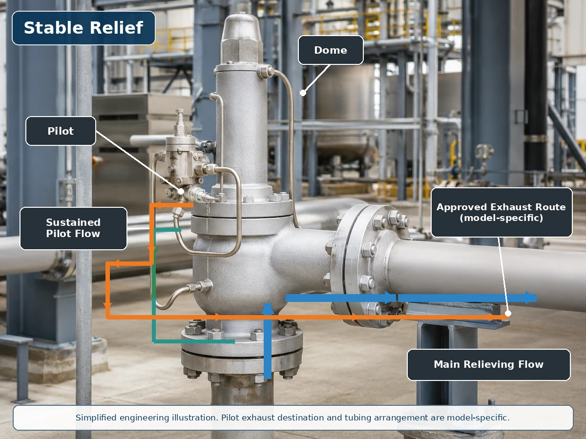
Vereinfachte technische Darstellung auf Basis einer realistischen Ventilinstallation. Tatsächliche Pilotversorgung, Dome- und Abgaswege sind modellspezifisch.
Strömungsweg während der Hauptventil-Abblasung
Während der Abblasung kann der anhaltende Pilotstrom den Dome-Druck entlüften oder regulieren. Bestätigen Sie die Pilotstrom-Basis, den Abgasbestimmungsort und die betrieblichen Konsequenzen, anstatt den Durchfluss als automatisches Ausschlusskriterium zu behandeln.
Pilotabgas und Dome-Wiederaufbau
Bestätigen Sie, ob das Abgas in die Atmosphäre, den Auslass oder ein anderes zugelassenes System geht und ob Auslassdruck, Kondensat, Entwässerung, Beheizung oder Winterisierung dies beeinflussen.
Was ist ein nicht strömender Pilot?
Ein nicht strömender Pilot erreicht einen stabilen Zustand, in dem der kontinuierliche Prozessmedium-Durchfluss durch den Piloten stoppt, während das Hauptventil geöffnet bleiben kann. Interne Sitze, Rückkopplungselemente und Dome-Steuerungsdetails bleiben modellspezifisch. Emerson Series 800 Handbuch beschreibt diesen stabilen Abblasezustand und weist auch auf transienten Durchfluss hin, wenn der Pilot den Hub ändert.

Vereinfachte technische Darstellung. Nicht durchströmt bedeutet nicht null transienten Durchfluss, null Leckage oder null Emissionen.
Transiente Betätigung und Dom-Druckentlastung
Beim Ansprechdruck reduziert der Pilot den Domdruck; während dieses Übergangs kann eine geringe Menge Dom- oder Prozessmedium durchströmen.
Stabile Entlastung ohne kontinuierlichen Pilotstrom
Bei stabilem Hub kann der Pilot Zufuhr und Abblasen isolieren, sodass der kontinuierliche Pilotstrom stoppt. Dies kann den dauerhaften Mediumverbrauch reduzieren, beweist jedoch keine Null-Leckage und beseitigt nicht die Risiken von Kontamination und Einfrieren.
Rückstellung und Dom-Neubefüllung
Wenn der Druck fällt, öffnet sich der Dom-Zufuhrpfad wieder und es kommt zu transientem Nachfüllstrom, bevor das Hauptventil schließt.
Vergleich durchströmter vs. nicht durchströmter Pilot
Scrollen Sie horizontal, um alle Spalten zu sehen.
| Technischer Faktor | Durchströmter Pilot | Nicht durchströmter Pilot | Auswahlfrage |
|---|---|---|---|
| Stabiler Pilotstrom während der Entlastung | Normalerweise während der relevanten Steuerphase aufrechterhalten. | Normalerweise nicht vorhanden bei stabilem Haupthub. | Was zeigt das ausgewählte Funktionsschema? |
| Transienter Pilotstrom | Vorhanden. | Vorhanden während der Pilotenbewegung oder Domsteuerung. | Welches Volumen und welche Abführroute gelten? |
| Prozessmediumverlust | Kann während anhaltender Entlastung durch den Piloten höher sein. | Normalerweise niedriger durch den Piloten bei stabiler Entlastung. | Ist das Medium gefährlich, wertvoll oder kontrolliert? |
| Atmosphärische Emissionen | Möglich, wenn der Pilotauslass zur Atmosphäre offen ist. | Weiterhin möglich während der Betätigung, wenn offen entlüftet wird. | Wo endet die Pilotabluft? |
| Kontaminationseinwirkung | Hängt vom durchgehenden Weg, Einschränkungen und Filterung ab. | Hängt von Sitzen, Kanälen, transientem Durchfluss und Filterung ab. | Ist das Medium für den gewählten Piloten geeignet? |
| Einfrieren und Eisbildung | Kontinuierliche Expansion kann relevant sein. | Transiente Expansion und feuchte Messleitungen können dennoch einfrieren. | Welche Mindesttemperatur und Feuchtigkeitsbedingungen gelten? |
| Gegendruckeinwirkung | Die Abluftführung kann die Pilotsteuerung beeinflussen. | Die Abgasführung kann auch die Pilotsteuerung beeinflussen. | Ist der Pilotabgas an den Auslass angeschlossen? |
| Schnapp- oder modulierende Wirkung | Getrennte Klassifizierung. | Getrennte Klassifizierung. | Welche Hauptventilwirkung ist erforderlich? |
| Abblaseleistung | Nicht durch den Pilot-Durchflusstyp bestimmt. | Nicht durch den Pilot-Durchflusstyp bestimmt. | Ist die dokumentierte Kapazität für den Entlastungsfall ausreichend? |
Strömend vs. nicht strömend ist nicht dasselbe wie Schnapp- vs. modulierend
Pilot-Durchfluss, Hauptventilwirkung, Messort und Pilotabgasziel sind unabhängige Entscheidungen. Ein strömender Pilot ist nicht automatisch schnappend, und ein nicht strömender Pilot ist nicht automatisch modulierend. Die Spezifikation 2900-40 von Baker Hughes liefert produktspezifische Beispiele für nicht strömende schnappende und nicht strömende modulierende Piloten; LESERs POSV-Übersicht erklärt separat das Pop- und Modulierhubverhalten.
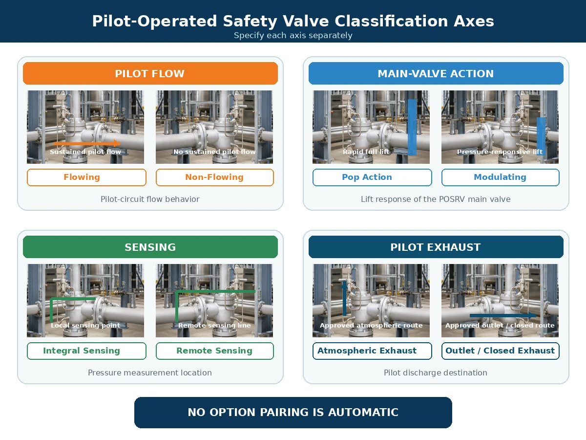
Vereinfachter technischer Vergleich. Verfügbare Kombinationen hängen vom gewählten Hersteller und der Produktserie ab.
Scrollen Sie horizontal, um alle Spalten zu sehen.
| Klassifikationsachse | Typische Optionen | Was es beschreibt | Was sie nicht beschreibt |
|---|---|---|---|
| Pilotströmung | Strömend / nicht strömend | Verhalten des Prozessmediums durch den Pilotkreis. | Hauptventil-Hubcharakteristik. |
| Hauptventil-Aktion | Pop / modulierend | Schnelles vollständiges Öffnen oder druckabhängiger Hub. | Ob der Pilotstrom kontinuierlich ist. |
| Erfassungsanordnung | Integral / fern | Wo der Pilot den Druck des geschützten Systems misst. | Ablassziel des Piloten. |
| Ablassanordnung | Atmosphäre / Auslass / zugelassener geschlossener Weg | Wo das Pilotmedium abgelassen wird. | Hauptventilwirkung oder Abblaseleistung. |
Wie Pilotablass und Gegendruck die Entscheidung beeinflussen
Atmosphärischer Ablass vs. Auslassablass
Atmosphärischer Pilotablass kann für giftige, brennbare, korrosive, riechende, umweltkontrollierte oder wertvolle Medien ungeeignet sein. Die Ableitung des Ablasses zum Hauptventilauslass kann die lokale Freisetzung in die Atmosphäre reduzieren, kann jedoch die Pilotablassverbindung dem Auslassdruck aussetzen.
Überlagerter und aufgebauter Gegendruck
Überlagerter Gegendruck besteht vor dem Öffnen des Ventils. Aufgebauter Gegendruck entsteht durch den Abblasestrom durch das Auslasssystem nach dem Öffnen. Beide Bedingungen können die Kräftebilanz des Hauptventils, den Pilotablass, die Domdruckreduzierung, den Hub, das erneute Aufsetzen und den Rückfluss beeinflussen. Überprüfen Sie diese Auswirkungen mit dem ZOBAI-Leitfaden zu Gegendruck und Faltenbalg.
Scrollen Sie horizontal, um alle Spalten zu sehen.
| Bedingung | Erforderliche Daten | Frage zum Pilotkreis | Entscheidungsgrenze |
|---|---|---|---|
| Konstanter überlagerter Gegendruck | Austrittsdruck vor dem Öffnen. | Wirkt er auf den Auslass, das Hauptventil oder beide? | Modellgrenze und Kapazitätsbasis bestätigen. |
| Variabler überlagerter Gegendruck | Minimales, normales und maximales Austrittsdruckprofil. | Kann die Variation Öffnung, Hub, Stabilität oder Wiedereinsetzen verändern? | Nicht anhand eines Durchschnittswerts freigeben. |
| Aufgebauter Gegendruck | Berechnung des Ableitsystems bei maßgeblichem Abblasedurchsatz. | Kann er den Pilotauslass einschränken oder die Leistung des Hauptventils verringern? | Beim erforderlichen Durchfluss bewerten, nicht im Normalbetrieb. |
| Pilotauslass an den Hauptauslass angeschlossen | Austrittsdruck während Öffnung, Abblasen und Wiedereinsetzen. | Wie werden Dom-Druckentlastung und Rücksetzen beeinflusst? | Freigabepflichtiges Abblasschema erforderlich. |
| Austrittsdruck kann Einlass- oder Domdruck überschreiten | Glaubwürdige Umkehrdruckdifferenz und Betriebssequenz. | Ist Rückflusssicherung oder eine andere Steuerung erforderlich? | Nicht annehmen, dass die Standard-Pilotanordnung Rückfluss verhindert. |
Rückfluss- und Pilotkreisschutz
Wenn der Austrittsdruck den Einlass- oder Domdruck überschreitet, kann das Entlastungsmedium in den Dom oder den Pilotkreis gelangen oder eine unbeabsichtigte Öffnungskraft am Hauptventil erzeugen. Herstellerspezifische Steuerungen können Rückschlagvorrichtungen, Rückflusssicherung und freigegebene Abblasanordnungen umfassen.
Medien-, Temperatur- und Verschmutzungsrisiken
Reines Gas und Dampf
Reines trockenes Gas reduziert einige Entwässerungs- und Verschmutzungsprobleme, aber Zusammensetzung, Expansionstemperatur, Dichtungen und Abblasklassifizierung müssen dennoch geprüft werden.
Kondensation, Vereisung und Hydrate
Feuchtigkeit, kleine Querschnitte und Tiefpunkte können Kondensation, Vereisung oder Hydratbildung verursachen. Ein nicht durchströmender Betrieb ersetzt nicht die Anforderungen an Entwässerung und Winterfestigkeit.
Verschmutzende oder erstarrende Medien
Rost, Zunder, Partikel, Wachs und Ablagerungen können Pilotkomponenten beeinträchtigen. Filter müssen geeignet, zugänglich und gewartet sein.
Temperatur und Zusatzmaßnahmen
Alle betroffenen Komponenten von Pilot- und Hauptventil prüfen, nicht nur das Gehäusematerial: benetzte Teile, Düse, Tellerventil, Führung, Rohrleitungen, Feder, Sitz/Dichtung, Membran und ggf. Faltenbalg in der gewählten Hauptventil-Konfiguration. Fernmontage, Beheizung, Kühlung oder andere Werkstoffe können erforderlich sein.
Scrollen Sie horizontal, um alle Spalten zu sehen.
| Medium oder Betriebszustand | Pilot-System-Risiko | Zu bestätigende Punkte | Wann ohne Prüfung nicht fortfahren |
|---|---|---|---|
| Trockenes, sauberes Gas oder Dampf | Expansionskühlung, Dichtungen und gefährliche Abgabe sind weiterhin relevant. | Pilotgehäuse, Rohrleitungen, Sitze, Dichtungen, Mindesttemperatur und Abgasweg. | Wenn Zusammensetzung, Abblasetemperatur oder Emissionsklasse unbekannt sind. |
| Nassgas oder kondensierbarer Dampf | Kondensat, Vereisung, Hydrate und blockierte Messleitungen. | Selbstentleerende Verlegung, Tiefpunkte, Entwässerungen, Beheizung und Filterposition. | Wenn Mess- und Entlüftungsleitungen nicht entleert oder winterfest gemacht werden können. |
| Verschmutztes oder partikelhaltiges Medium | Blockierte Drosselstellen, beschädigte Sitze, verstopfte Filter und Verunreinigung der Steuerkammer. | Partikeleigenschaften, Filtration, Durchgangsquerschnitt und Wartungszugang. | Wenn die Eignung oder eine wartbare Schutzstrategie nicht dokumentiert ist. |
| Korrosives Medium | Angriff auf Pilotgehäuse, Rohrleitungen, benetzte Innenteile, Sitze und Weichdichtungen. | Werkstoffe, Rohrleitungen, Sitz-/Dichtungskompatibilität und Aufzeichnungen. | Wenn die Bewertung nur auf dem Gehäusewerkstoff des Hauptventils basiert. |
| Polymerisierender, kristallisierender oder erstarrender Betrieb | Kleben, blockierte Durchgänge, Ablagerungen und beeinträchtigte Steuerkammersteuerung. | Temperaturregelung, Spülung/Spülen, Toträume und Wartungsgrundlage. | Wenn sich in unzugänglichen Leitungen Ablagerungen bilden können. |
| Hoch- oder Niedertemperaturbetrieb | Pilotfeder, Sitze, Dichtungen, Membran, Rohrleitungen und Filter können Temperaturen ausgesetzt sein, die von denen des Hauptkörpers abweichen. | Betriebs- und Abblasetemperaturen, Umgebungsextreme, Fernmontage, Heiz- oder Kühlanordnungen. | Wenn nur die Temperaturbewertung des Hauptventilkörpers geprüft wurde. |
| Flüssigkeits-, Verdampfungs- oder Zweiphasenbetrieb | Dynamisches Verhalten, Kapazitätsbasis und Pilotstabilität können sich von Gasbetrieb unterscheiden. | Exakte Phasengrundlage, Abblasebedingungen und ausdrückliche Herstellergenehmigung. | Wenn die Phase angenommen statt berechnet oder bestätigt wird. |
Installationskontrollen: Was zu tun ist und was zu vermeiden ist
Die Pilotarchitektur kann nur dann wie vorgesehen funktionieren, wenn Einlass, Auslass, Fühlleitung, Domrohrleitung und Pilotabblasung des Hauptventils als integriertes Druckschutzsystem installiert sind. Für detaillierte Kontrollen von Einlass, Auslass, Abstützung und Fühlleitung verwenden Sie die Installationsanleitung für Sicherheitsventile.
Soll
- Halten Sie den Haupteinlass des Ventils kurz und direkt und bewerten Sie den Einlassdruckverlust für den maßgebenden Entlastungsfall.
- Stützen Sie die Austrittsleitung unabhängig ab und prüfen Sie Reaktionskräfte, Wärmeausdehnung und Sammelleitungsbelastungen.
- Verlegen Sie Fernfühlerleitungen so, dass Druckverlust, Pulsation, Flüssigkeitsansammlungen und versehentliche Absperrung minimiert werden.
- Stützen Sie die Pilotrohrleitungen ab und bewahren Sie den vom Hersteller geforderten Innendurchmesser, die Fittings und die Anschlusspunkte.
- Führen Sie den Pilotabblas an einen zugelassenen sicheren Ort und bewerten Sie den auf diese Leitung ausgeübten Druck.
- Sorgen Sie für Entwässerung, Beheizung, Isolierung oder Umweltschutz, wo es der Betrieb und die Herstelleranweisungen erfordern.
- Halten Sie Entlüftungen, Abläufe, Filter, Prüfanschlüsse und Wartungsverbindungen zugänglich.
Don't
- Schließen Sie die Fühlerleitung nicht an einen beliebigen Punkt an und gehen Sie nicht davon aus, dass der Austrittsdruck der Druck des geschützten Systems ist.
- Fügen Sie keine Absperrventile in Fühler- oder Pilotleitungen ein, ohne eine zugelassene verriegelte oder kontrollierte Anordnung.
- Reduzieren Sie nicht die Rohrgröße, fügen Sie keine langen ungestützten Strecken hinzu oder erzeugen Sie keine Tiefpunkte, ohne die Auswirkung auf das Ansprechverhalten zu prüfen.
- Blockieren, verstopfen oder kombinieren Sie eine Pilotentlüftung oder einen Ablass nicht, es sei denn, die gewählte Konstruktion erlaubt dies ausdrücklich.
- Lassen Sie das Hauptventil nicht das Gewicht oder die Reaktionslast schwerer Austrittsleitungen tragen.
- Behandeln Sie Begleitheizung, Spülung oder Filter nicht als Allheilmittel für ein ungeeignetes Medium.
- Ändern Sie die Abgasführung nicht, ohne Gegendruck, Ex-Bereich und Umweltanforderungen zu prüfen.
Montage-Haltepunkt: Jede Änderung der Messstelle, der Pilotleitung, der Abgasführung, des Austrittskopfes oder der Isolationsphilosophie erfordert eine hersteller- und projektspezifische Überprüfung vor der Inbetriebnahme.
Häufige Fehlerbilder und Wartungsprüfungen
Scrollen Sie horizontal, um alle Spalten zu sehen.
| Beobachtetes Symptom | Mögliche Ursache im Pilotkreis | Andere mögliche Ursache | Erforderliche Prüfung |
|---|---|---|---|
| Hauptventil öffnet spät | Verstopfte Messleitung oder Pilot-Einlass. | Falsche Druckmessung oder Problem mit dem Einstelldruck. | Messstrecke und kalibrierte Prüfdaten verifizieren. |
| Hauptventil öffnet früh | Leckage am Pilot-Sitz oder falsche Pilot-Einstellung. | Druckpulsation oder ungeeigneter Messpunkt. | Pilot und Druckquelle prüfen. |
| Das Hauptventil erreicht nicht den erwarteten Hub | Eingeschränkter Pilotabblas oder unzureichende Druckentlastung der Dome-Kammer. | Unzureichender Prozessdurchfluss oder zu hoher Gegendruck. | Pilotabblas und installiertes System überprüfen. |
| Das Hauptventil zykliert | Pilotinstabilität oder Pulsation in der Fühlleitung. | Überdimensionierung, Einlassverlust oder variabler Gegendruck. | Das gesamte Entlastungssystem überprüfen. |
| Langsames Wiedereinsetzen | Eingeschränkter Nachladeweg der Dome-Kammer. | Reibung im Hauptventil oder ungeeigneter Blowdown. | Pilot und Hauptventil inspizieren. |
| Pilotventil friert ein | Nasses Medium und Expansionskühlung. | Umgebungseinwirkung oder unzureichende Entwässerung. | Feuchtigkeitskontrolle und Winterisierung prüfen. |
Nicht allein anhand des Symptoms diagnostizieren. Ein zyklisches, spät öffnendes oder niedrighubiges Ventil kann durch den Pilotkreis verursacht werden, aber auch durch Einlassdruckverlust, Überdimensionierung des Ventils, unzureichenden Prozessdurchfluss, variablen Gegendruck, Hauptventilreibung oder ungeeignete Messstellenposition. Bewahren Sie Druckaufzeichnungen, Pilotzustand, Rohrleitungskonfiguration und Testergebnisse auf, bevor Sie die Piloteinstellung ändern.
Wartung muss nach einem genehmigten Verfahren zur Isolierung, Druckentlastung und Prüfung erfolgen. Blockieren Sie keine Pilotentlüftungen oder Abflüsse, ändern Sie keine Rohrleitungen ohne Beibehaltung der erforderlichen Konstruktion und leiten Sie die Abblaskapazität nicht aus einem Ansprechdrucktest ab.
Ein Entscheidungsablauf für die Auswahl der Pilotarchitektur
1. Entlastungsfall definieren
- Geschützte Ausrüstung und maßgebliches Überdruckszenario; verwenden Sie den API 521 Druckentlastungssysteme Leitfaden, wenn die Projektbasis API 521 übernimmt
- Betriebsdruck, MAWP oder Auslegungsdruck und Ansprechdruck
- Zulässiger Überdruck und Aufaddierung
- Erforderliche Entlastungskapazität und Berechnungsbasis
- Entlastungsdruck, Entlastungstemperatur, Medium und Phase
2. Pilotstrom- und Abblasanforderungen festlegen
- Ob ein kontinuierlicher Pilotstrom zulässig ist
- Anforderung an atmosphärische, Auslass- oder geschlossene Abblasung
- Schnapp- oder modulierende Wirkung
- Integrale oder ferngesteuerte Messung
- Anforderungen an Rückströmungsschutz und Feldprüfung
3. Betriebs- und Ausfallrisiken prüfen
- Verschmutzung, Korrosion und Verfestigung
- Kondensation, Vereisung und Hydratbildung
- Vibration, Pulsation und Anordnung der Messleitung
- Umwelteinflüsse und Wartungszugang
4. Herstellerspezifische Auslegung bestätigen
- Pilot-Betriebsschema und Modell-Datenblatt
- Druck-, Temperatur-, Phasen- und Gegendruckgrenzen
- Werkstoffe, Dichtungen, Filter, Heizungen und Ableitungen
- Dokumentierte Kapazität und erforderliche Projektdokumente
Wann dieser Vergleich nicht ausreicht
Wählen Sie kein Ventil allein anhand des Vergleichs von durchströmten/nicht durchströmten Systemen aus, wenn einer der folgenden Punkte ungeklärt bleibt:
- Das geschützte Gerät oder das maßgebliche Entlastungsszenario wurde nicht identifiziert.
- Die erforderliche Entlastungskapazität, der Entlastungsdruck, die Entlastungstemperatur oder die Phasengrundlage fehlen.
- Der überlagerte oder aufgebaute Gegendruck ist variabel, unbekannt oder wird durch eine gemeinsame Sammelleitung beeinflusst.
- Das Medium kann einfrieren, polymerisieren, kristallisieren, korrodieren, verschmutzen oder Feststoffe mitführen.
- Fernmessung, geschlossener Pilot-Abgas, Rückströmungsschutz oder Feldprüfung sind erforderlich.
- Das ursprüngliche Pilot-Schema, die Abluftführung oder die Messquelle des Ersatzventils ist nicht verfügbar.
- Der ausgewählte Hersteller hat den Einsatz, die Werkstoffe, die Pilotwirkung und das Zubehör nicht bestätigt.
Entscheidungsregel: Wenn eine fehlende Eingabe die Kapazität, die Pilotstabilität, die Abblasesicherheit, die Materialverträglichkeit oder die Code-Akzeptanz verändern kann, erfassen Sie sie als “Noch zu bestätigen”, anstatt sie in eine angenommene Tatsache umzuwandeln.
Zusammengesetzte Ingenieurszenarien
Die folgenden Szenarien sind zusammengesetzte Schulungsbeispiele. Sie stellen keine namentlich genannten Kunden, verifizierte Vorfälle oder abgeschlossene ZOBAI-Projekte dar.
Reines Hochdruckgas mit begrenzten atmosphärischen Emissionen
Beobachtetes Problem: Eine RFQ spezifiziert “nicht strömend erforderlich” nur, weil lokale atmosphärische Emissionen begrenzt sind. Technische Ursache: Die Anfrage behandelt stabilen Pilotstrom, als ob es der einzige mögliche Freisetzungsweg wäre. Korrektur: Vergleichen Sie transienten Pilotauslass, stabilen Pilotstrom, Hauptventilabblasung, Auslassführung, Gegendruck und dokumentierte Kapazität. Vorbeugung: Verlangen Sie das ausgewählte Pilot-Schema und einen genehmigten Auslassbestimmungsort vor der Modellfreigabe.
Nassgas mit Kondensation und Frostgefahr
Beobachtetes Problem: Ein Nassgas-Pilot reagiert langsam oder wird bei niedriger Umgebungstemperatur instabil. Technische Ursache: Feuchtigkeit sammelt sich in Mess- oder Auslass-Tiefpunkten und gefriert während der Druckreduzierung. Korrektur: Selbstentleerende Leitungsführung wiederherstellen und die vom Hersteller zugelassene Entwässerungs-, Beheizungs- oder Winterfestmachungsanordnung anwenden. Vorbeugung: Mindesttemperatur, Feuchtigkeitszustand, Leitungsführung, Filter und Wartungszugang während der Konstruktionsprüfung bestätigen.
Ersatzventil mit unbestätigter Pilot-Abluftführung
Beobachtetes Problem: Ein Ersatz-POSRV entspricht den Flanschgrößen und dem Ansprechdruck, reproduziert jedoch nicht das ursprüngliche Betriebsverhalten. Technische Ursache: Der ursprüngliche Pilottyp, die Messquelle, die Abluftführung, die Kapazitätsbasis oder der Gegendruckzustand wurden nicht verifiziert. Korrektur: Die Entlastungsbasis rekonstruieren und das vollständige Betriebsschema sowie die dokumentierte Kapazität vergleichen. Vorbeugung: Ersatzteile durch Änderungsmanagement, genehmigte Zeichnungen, Prüfprotokolle, Typenschilddaten und Rückverfolgbarkeit kontrollieren.
Workflow zur Überprüfung von Ersatzventilen
Ein pilotgesteuertes Sicherheitsventil sollte nicht allein durch Übereinstimmung von Aussehen, Eingangsgröße, Ausgangsgröße und Ansprechdruck ersetzt werden.
Die Druckentlastungsbasis rekonstruieren
Das geschützte Gerät, das maßgebliche Entlastungsszenario, MAWP oder Auslegungsdruck, Ansprechdruck, zulässiger Überdruck, erforderliche Kapazität und Entlastungsbedingungen bestätigen.
Die ursprüngliche Pilotarchitektur identifizieren
Das ursprüngliche Datenblatt, Typenschild, Betriebsschema und Wartungsanweisungen beschaffen. Fließend oder nicht fließend, Pop oder modulierend, Messquelle und Abluftführung bestätigen.
Installierte Verbindungen prüfen
Pilotversorgung, Domleitung, Fühlerleitung, Ausblasleitung, Entwässerungen, Filter, Heizungen, Prüfanschlüsse und alle Rückflussverhinderer nachverfolgen.
Reale Betriebsbedingungen vergleichen
Medium, Phase, Verunreinigung, Betriebs- und Entlastungstemperaturen, überlagerter und aufgebauter Gegendruck, Umgebungsbedingungen und Anforderungen an gefährliche Ausblasungen prüfen.
Kapazität und Druckverhalten getrennt prüfen
Erforderliche Kapazität mit der dokumentierten Kapazität des vorgeschlagenen Ventils abgleichen und Ansprechdruck, Blowdown und Wirkungsweise mit der Projektbasis bestätigen.
Installationsabweichungen genehmigen
Messpunkt, Rohrleitungen, Pilotausblasung, Auslassanordnung, Werkstoffe oder Zubehör nicht ohne dokumentierte Prüfung ändern.
Prüf- und Freigabenachweise festlegen
Ansprechdruckprüfung, Sitzdichtheit, Funktionsprüfungen, Materialzeugnisse, Kapazitätsnachweise, Zeichnungen, Handbücher und Abnahmefreigabe vor Versand oder Inbetriebnahme vereinbaren.
Was Käufer in das Datenblatt und die RFQ aufnehmen sollten
Nur “pilotgesteuertes Sicherheitsventil”, Nennweite und Ansprechdruck anzugeben, reicht nicht aus. Der Lieferant benötigt vollständige Prozess-, Entlastungs-, Pilotkreis- und Dokumentationsanforderungen.
Häufige Lücke in RFQ-Anfragen: Anfragen nennen oft “pilotgesteuert”, Ansprechdruck und Anschlussgröße, lassen aber das Entlastungsszenario, die erforderliche Kapazität, die Entlastungstemperatur, den Gegendruck, die Messquelle und das Ziel des Pilot-Abgases außer Acht. Diese Auslassungen sollten die Modellbestätigung stoppen und nicht durch Annahmen gefüllt werden.
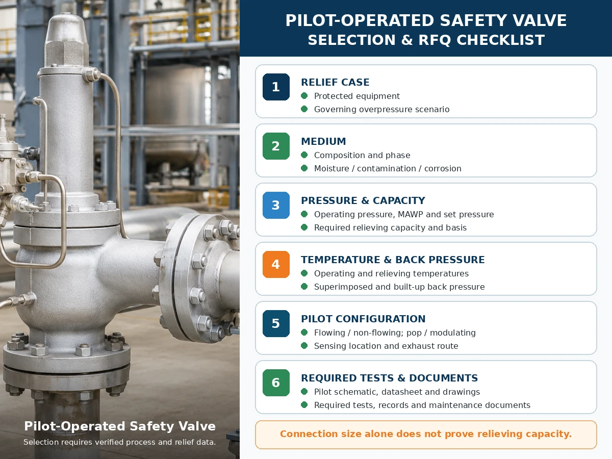
Nur technische Checkliste. Die endgültige Modellauswahl hängt von verifizierten Prozessdaten, Herstellerinformationen, geltenden Normen und der Projektprüfung ab.
Scrollen Sie horizontal, um alle Spalten zu sehen.
| Erforderliche Eingaben | Warum es wichtig ist | Status |
|---|---|---|
| Geschützte Ausrüstung und maßgebliches Entlastungsszenario | Definiert die Druckschutzaufgabe und die erforderliche Last. | Noch zu bestätigen |
| Medium, Zusammensetzung und Phase | Beeinflusst Pilot, Dichtungen, Abgasbehandlung und Kapazitätsbasis. | Noch zu bestätigen |
| Betriebsdruck, MAWP/Konstruktionsdruck und Ansprechdruck | Definiert Betriebsmarge und Druckgrenze. | Noch zu bestätigen |
| Zulässiger Überdruck und Aufaddierung | Beeinflusst die Auslegung und die anzuwendende Entlastungsbasis. | Noch zu bestätigen |
| Erforderliche Entlastungskapazität und Berechnungsbasis | Bestimmt die erforderliche dokumentierte Ventilkapazität. | Noch zu bestätigen |
| Betriebs- und Entlastungstemperaturen | Steuert Materialien, Dichtungen, Pilotanordnung und Kapazitätsbasis. | Noch zu bestätigen |
| Überlagerter und aufgebauter Gegendruck | Beeinflusst das Verhalten von Hauptventil und Pilot-Abgas. | Noch zu bestätigen |
| Strömend/nicht strömend, pop/modulierend, Erfassung und Abblasen | Definiert vier separate Entscheidungen für das Pilotventilsystem. | Noch zu bestätigen |
| Werkstoffe, Filterung, Beheizung, Entwässerung und Wartungszugang | Behandelt Servicekompatibilität und Ausfallkontrollen. | Noch zu bestätigen |
| Anwendbarer Code, Prüfung und Dokumente | Definiert das Projektnachweispaket. | Noch zu bestätigen |
Prüf- und Dokumentationsmatrix
Prüfung und Dokumentation sollten verschiedene Teile der Nachweiskette für den Druckschutz aufzeigen. Ein Prüfbericht sollte nicht verwendet werden, um Ergebnisse zu beanspruchen, die er nicht belegt.
Scrollen Sie horizontal, um alle Spalten zu sehen.
| Test oder Dokument | Was es unterstützen kann | Was es allein nicht beweist | RFQ-Prüfung |
|---|---|---|---|
| Pilot- oder montageventil-Einstelldruckprüfung | Ansprechdruckverhalten unter dem angegebenen Verfahren. | Kapazität, Feldgegendruckverhalten oder Prozesskompatibilität. | Medium, Verfahren, Akzeptanzkriterien und Berichtsformat angeben. |
| Sitzdichtheitsprüfung / API 527 Dichtheitsprüfung Leitfaden, sofern anwendbar | Leckage unter den angegebenen Bedingungen und Kriterien. | Null Leckage in allen Betriebsarten oder Betriebsbedingungen. | Prüfmethode, Prüfdruck, Medium und Akzeptanzkriterien angeben. |
| Funktionstest Pilot-/Hauptventil | Pilotbetätigung, Domsteuerung, Hauptventilbewegung und Rückstellung. | Volle Feldkapazität oder ungeprüfte Abblaseleistung der Abgasleitung. | Architektur, Wirkungsweise und enthaltenes Zubehör bestätigen. |
| Kapazitätstabelle, Zertifikat oder Berechnungsnachweis | Dokumentierte Entlastungsleistung für die gewählte Ausführung. | Eignung für eine andere Phase, Temperatur, Gegendruck oder ein anderes Medium. | Modell, Öffnung, Fluidbasis und geforderte Nachweise abgleichen. |
| Allgemeine Anordnung und Funktionsschema des Piloten | Anschlüsse, Strömungswege, Fühler, Abblas- und Zubehörteile. | Werkstoffverträglichkeit oder Kapazität, sofern nicht separat dokumentiert. | Erfordern die für die Herstellung und Installation verwendete Zeichnungsrevision. |
| Materialaufzeichnungen | Festgelegte Werkstoffidentität für aufgeführte drucktragende und mediumberührte Komponenten. | Korrosionseignung ohne anwendungsspezifische Werkstoffprüfung. | Festlegung, welche Komponenten und welche Rückverfolgbarkeitsstufe erforderlich sind. |
| Datenblatt, Typenschild und Prüffreigabe | Konfiguration, Ansprechdruck, Modellidentifikation und vereinbarter Prüfstatus. | Eine vollständige Auslegungsberechnung oder eine allgemeine Zertifizierung. | Prüfung der Übereinstimmung von Bestellung, Zeichnung, Prüfberichten und endgültigem Typenschild. |
| Installations- und Wartungsanleitung | Freigegebene Leitungs-, Fühler-, Abblas-, Prüf-, Wartungs- und Ersatzteilhinweise. | Projektfreigabe, wenn die installierte Anordnung von den Anweisungen abweicht. | Die exakte Produktreihen-Revision in das Dokumentenpaket aufnehmen. |
Reparatur- und Rücksetzaufzeichnungen: Sofern vom anwendbaren Reparaturprogramm oder der Projektspezifikation gefordert, sind die Daten zu Ansprechdruck und Sitzdichtheit im Anliefer- und Ablieferzustand, Ersatzteilaufzeichnungen, Neuplombierungs- oder Typenschildkontrollen, Rückverfolgbarkeit und Genehmigung von Änderungsmanagement aufzubewahren. Die API-527-Sitzdichtheitsrichtlinie ersetzt nicht die Auslegung oder die Überprüfung der dokumentierten Kapazität.
Normen und Quellenhinweise
Herstellerspezifische Betriebsnachweise sind neben den entsprechenden Aussagen zu strömendem, nicht strömendem und Pop-/Modulierbetrieb oben verlinkt. Diese Dokumente unterstützen nur die genannten Produktfamilien und dürfen nicht als universelle POSRV-Leistungsdaten betrachtet werden.
- API 520 Teil I, 10. Ausgabe — offizieller Hinweis zur API-Auslegungs- und Auswahlveröffentlichung.
- API 520 Teil II, 7. Ausgabe — offizieller Hinweis zur API-Installationsveröffentlichung.
- ASME BPVC Abschnitt XIII, Ausgabe 2025 — Regeln für den Überdruckschutz.
- ISO 4126-4:2013 — pilotgesteuerte Sicherheitsventile; ISO listet die Veröffentlichung als 2025 überprüft und bestätigt.
Diese Referenzen haben unterschiedliche Anwendungsbereiche. Bestätigen Sie die projektbezogene Ausgabe, den Code für geschützte Ausrüstung, die Zuständigkeit, den Hersteller-/Modellumfang und die erforderliche Dokumentation. Ein Normname ist kein Beweis dafür, dass jedes ZOBAI-Modell jede Zertifizierung trägt.
Häufig gestellte Fragen
Was ist der Unterschied zwischen einem durchströmenden und einem nicht durchströmenden pilotgesteuerten Sicherheitsventil?
Ein durchströmter Pilot hält während des relevanten stabilen Entlastungszustands einen konstruierten Pilotpfad aufrecht. Ein nicht durchströmter Pilot stoppt den kontinuierlichen Pilotstrom bei einem stabilen Hauptventilzustand, obwohl während der Betätigung und der Domaufladung ein transienter Strom auftreten kann.
Bedeutet ein nicht durchströmter Pilot, dass niemals Prozessmedium durch den Pilot strömt?
Nr. Medium kann während der Betätigung des Piloten, der Änderung des Domdrucks oder der Wiederbefüllung des Doms strömen. Nichtströmend bezieht sich auf den stabilen Zustand, nicht auf jeden Augenblick.
Ist ein nicht durchströmter Pilot immer besser als ein durchströmter Pilot?
Nr. Die Eignung hängt vom Medium, der Abgasleitung, der Temperatur, der Verschmutzung, dem Gegendruck, der erforderlichen Kapazität, der Wirkungsweise und der gewählten Herstellerausführung ab.
Ist fließend vs. nicht fließend dasselbe wie Pop-Action vs. modulierend?
Nr. Strömend oder nicht strömend beschreibt den Durchfluss im Pilotkreis. Pop- oder modulierende Ausführung beschreibt das Hubverhalten des Hauptventils. Bitte getrennt angeben.
Wohin führt die Pilotabluft?
Je nach Bauart kann die Pilotabluft in die Atmosphäre, in den Hauptaustritt oder in einen anderen zugelassenen geschlossenen Weg abgeführt werden. Bestätigen Sie das Schema und die Auswirkung des Gegendrucks.
Welcher Pilottyp ist besser für gefährliche oder wertvolle Prozessmedien geeignet?
Eine nicht durchströmende Bauweise kann den kontinuierlichen Pilotmedium-Verlust reduzieren, jedoch müssen kurzzeitiges Abblasen, Hauptabblasen, Leckagekriterien, Leitungsführung und Modelltauglichkeit weiterhin geprüft werden.
Kann ein nicht durchströmter Pilot einfrieren oder verschmutzen?
Ja. Fühlerleitungen, Filter, Drosselstellen, Dome-Kanäle und Auslässe können Feuchtigkeit ansammeln, einfrieren oder verschmutzen. Entwässerung, Filtration und Winterschutz bleiben serviceabhängig.
Welche Informationen sind vor der Auswahl der Pilotarchitektur erforderlich?
Geschütztes Equipment, Entlastungsszenario, Medium und Phase, Druckdaten, erforderliche Kapazität, Entlastungstemperatur, Gegendruck, Erfassung, Abblasleitung, Rohrleitungen, Werkstoffe, Wirkungsweise und erforderliche Dokumente angeben.
Normen und technische Grenzen
API 520 Teil I behandelt die Auslegung und Auswahl, während API 520 Teil II die Installation innerhalb der angegebenen Anwendungsbereiche behandelt. ASME BPVC Abschnitt XIII bietet einen Rahmen für den Überdruckschutz. ISO 4126-4 behandelt pilotgesteuerte Sicherheitsventile als Produktnorm; sie ist keine Anwendungsnorm für das geschützte System. Überprüfen Sie die im Projekt übernommene Ausgabe, die geltende Ausrüstungsnorm, die Rechtsordnung und die produktspezifischen Daten des Herstellers.
Die endgültige Auswahl hängt ab von der geschützten Ausrüstung, dem maßgeblichen Entlastungsszenario, dem tatsächlichen Medium und der Phase, dem Betriebsdruck, dem MAWP oder Auslegungsdruck, dem Ansprechdruck, der erforderlichen und dokumentierten Entlastungskapazität, der Entlastungstemperatur, dem überlagerten und aufgebauten Gegendruck, der Einlass- und Auslassleitung, allen betroffenen Werkstoffen und Dichtungskomponenten, der Pilotkonfiguration, der übernommenen Normausgabe, der Projektspezifikation und den geltenden lokalen behördlichen Anforderungen.
Technische Prüfung eines pilotgesteuerten Sicherheitsventils anfragen
Die endgültige Wahl zwischen durchströmenden und nicht durchströmenden pilotgesteuerten Sicherheitsventilen sollte dem tatsächlichen Entlastungsszenario, der erforderlichen Kapazität, dem Medium und der Phase, der Entlastungstemperatur, dem Gegendruck, der Anordnung von Steuer- und Entlüftungsleitung, den Werkstoffen, der Rohrleitung und der geforderten Dokumentation folgen. Bitte senden Sie diese Angaben, bevor Sie eine Modellempfehlung anfragen.