Comparação de engenharia de válvulas de segurança pilotadas Válvulas de segurança pilotadas com fluxo e sem fluxo diferem principalmente no circuito piloto durante o alívio estável. Um projeto com fluxo normalmente mantém uma purga ou fluxo controlado; um projeto sem fluxo normalmente interrompe o fluxo contínuo do piloto após a válvula principal atingir uma condição de alívio estável, embora o fluxo transitório ainda possa ocorrer durante a atuação, …

Comparação de engenharia de válvulas de segurança pilotadas
Válvulas de segurança pilotadas com fluxo e sem fluxo diferem principalmente no circuito piloto durante o alívio estável. Um projeto com fluxo normalmente mantém uma purga ou fluxo controlado; um projeto sem fluxo normalmente interrompe o fluxo contínuo do piloto após a válvula principal atingir uma condição de alívio estável, embora o fluxo transitório ainda possa ocorrer durante a atuação, ajuste de abertura, reassentamento e recarga da câmara. A distinção é importante quando a exaustão do piloto, emissões, umidade, contaminação, formação de gelo, contrapressão ou alívio de longa duração afetam a especificação. Não define ação pop ou modulante, local de sensoriamento ou capacidade de alívio. A pressão de ajuste e o tamanho da conexão também não comprovam que a válvula selecionada tem capacidade documentada adequada. Antes da seleção, confirme o equipamento protegido, cenário de alívio, meio e fase, pressão de operação, MAWP ou pressão de projeto, pressão de ajuste, capacidade necessária, temperatura de alívio, contrapressão superimposta e acumulada, fonte de sensoriamento, destino da exaustão, materiais e documentos necessários. Envie essas condições para uma revisão de engenharia.
Válvulas de segurança pilotadas com fluxo contínuo vs. sem fluxo contínuo: resposta rápida
Fluxo contínuo ou sem fluxo contínuo descreve o comportamento do meio de processo através do circuito piloto. Um piloto com fluxo contínuo normalmente mantém um fluxo projetado durante o estado de alívio estável relevante; um piloto sem fluxo contínuo normalmente interrompe o fluxo contínuo do piloto na abertura estável. Nenhum dos termos define a ação da válvula principal, a localização da tomada de pressão, o destino da exaustão ou a capacidade de alívio.
Um piloto sem fluxo contínuo ainda pode permitir um volume transiente durante a atuação, mudança de pressão da câmara ou repressurização da câmara. Não deve ser descrito como fluxo zero, emissão zero ou isento de manutenção.
Revise a arquitetura selecionada dentro do válvula de segurança pilotada sistema completo, em vez de tratar a classificação do fluxo do piloto como uma especificação completa.
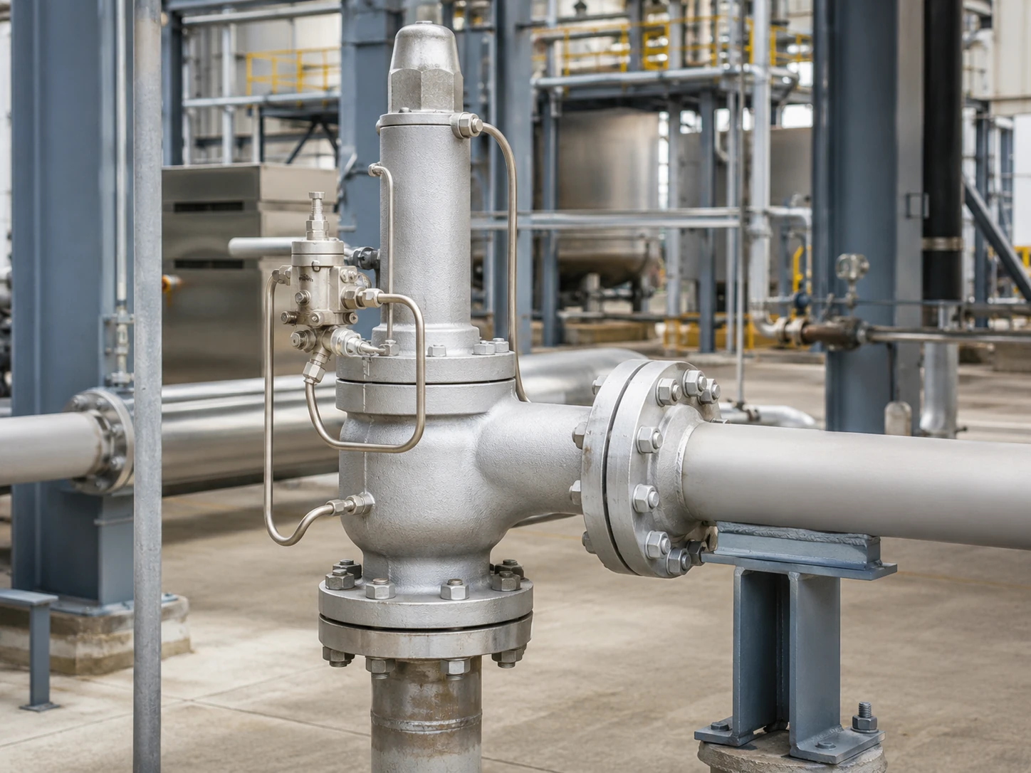
Visualização conceitual realista. A geometria final da válvula, a tomada de pressão, o roteamento da exaustão, a faixa de pressão e a capacidade documentada devem ser confirmados com o modelo selecionado.
Limite de seleção: Nenhum tipo de piloto é universalmente melhor. A arquitetura do piloto não estabelece a capacidade necessária, o orifício selecionado, a contrapressão aceitável, a compatibilidade de materiais ou a adequação ao código. Essas decisões exigem o cenário de alívio aplicável e a documentação específica do fabricante.
Matriz de Seleção Preliminar
Esta matriz é uma ferramenta de triagem, não uma recomendação de modelo. Ela identifica as questões que devem ser resolvidas antes de especificar um piloto com fluxo contínuo ou sem fluxo contínuo.
Role horizontalmente para revisar todas as colunas.
| Condição de serviço ou do projeto | Por que Importa | Revisão de piloto com fluxo contínuo | Revisão de piloto sem fluxo contínuo | Ponto de retenção de engenharia |
|---|---|---|---|---|
| A exaustão atmosférica local do piloto é restrita | A ventilação do piloto pode ser inaceitável para meios perigosos, valiosos ou regulamentados. | Confirme o fluxo contínuo do piloto e o roteamento aprovado. | Confirme a exaustão transitória e a condição estável do modelo selecionado. | Adie a seleção até que o destino da exaustão e os efeitos da pressão de saída sejam definidos. |
| Os eventos de alívio podem ser prolongados | A longa duração pode aumentar a perda de meio do piloto e a carga do sistema de exaustão. | Solicite dados de ciclo operacional e fluxo do piloto. | Confirme quando o fluxo contínuo para e como o levantamento é controlado. | Somente a duração não decide a arquitetura; capacidade e estabilidade ainda governam. |
| Gás úmido, baixa temperatura ambiente ou risco de hidrato | Restrições, filtros, linhas de sensoriamento e caminhos de exaustão podem congelar ou acumular líquido. | Revise o resfriamento por expansão, a drenagem, o aquecimento e os limites de temperatura. | Revise a expansão transiente, a recarga do domo e as linhas de sensoriamento úmidas. | Aguarde até que o controle de umidade e a temperatura mínima sejam confirmados. |
| Meio sujo, polimerizante ou com partículas | Passagens e sedes pequenas podem obstruir, aderir ou erodir. | Avalie a exposição contínua de restrições e filtros. | Avalie sedes, caminhos transientes, filtragem e contaminação do domo. | Somente um filtro não torna o serviço aceitável. |
| Pressão de saída variável ou coletor de descarga comum | A pressão de saída pode alterar a exaustão do piloto e o equilíbrio de forças da válvula principal. | Confirme como a pressão de saída atua na exaustão e no circuito da câmara superior. | Confirme o comportamento de alívio estável, rearme e fluxo reverso. | Separe a contrapressão superimposta e a contrapressão acumulada. |
| A detecção remota é necessária | O roteamento da linha de detecção, a perda de pressão, a pulsação, a drenagem e o isolamento podem afetar a operação. | Confirme se o sinal remoto é compatível com o circuito piloto selecionado. | Confirme o controle da câmara e a resposta transitória com o arranjo de detecção remota. | Não infira a adequação da detecção remota a partir da classificação do fluxo do piloto. |
| Serviço com líquido, flashing ou duas fases é possível | O comportamento das fases afeta a capacidade, a dinâmica do piloto e a estabilidade da descarga. | Exija aprovação explícita do fabricante para a fase real e o caso de alívio. | Exija aprovação explícita do fabricante para a fase real e o caso de alívio. | A comparação apenas entre fluxo e não fluxo é insuficiente. |
Ponto de retenção do RFQ: Não converta uma preferência como “sem fluxo necessário” em uma seleção final de modelo até que a carga de alívio, fase, temperatura de alívio, contrapressão, fonte de sensoriamento e destino do exaustor estejam disponíveis.
Como uma Válvula de Segurança Pilotada Controla a Válvula Principal
Válvula Principal, Piloto e Pressão da Câmara
Um sistema típico inclui a válvula de alívio principal, piloto, câmara ou câmara de controle, caminho de sensoriamento, tubulação e exaustor do piloto. Abaixo da pressão de ajuste, a pressão do processo normalmente mantém a pressão da câmara e a força de fechamento da válvula principal.
Na pressão de ajuste, o piloto altera o caminho da pressão da câmara para que a pressão de entrada possa abrir a válvula principal. À medida que a pressão cai em direção à pressão de fechamento do piloto, a câmara é repressurizada e a válvula principal reassenta.
Pressão de Sensoriamento e Exaustor do Piloto
A pressão pode ser sensoriada integralmente ou remotamente. O exaustor do piloto pode ir para a atmosfera, a saída principal ou outra rota fechada aprovada; nenhuma escolha é determinada pela classificação de fluxo ou não fluxo.
A Operação do Piloto Não Substitui a Verificação de Capacidade
A resposta à pressão de ajuste não prova que a válvula pode passar a carga de alívio governante. Confirme a capacidade necessária, o orifício selecionado e a capacidade documentada separadamente; o tamanho da conexão não é uma base de capacidade. Consulte dimensionamento de válvulas de segurança e capacidade de alívio certificada.
Capacidade Necessária, Válvula Selecionada e Evidência São Diferentes
A arquitetura do piloto controla a válvula principal, mas não substitui a cadeia de seleção de capacidade. Cada item abaixo responde a uma pergunta de engenharia diferente.
Os valores de capacidade para vapor, ar ou gás, líquido e duas fases não são intercambiáveis. A base de capacidade selecionada deve corresponder ao meio de alívio real, fase, pressão, temperatura, contrapressão e método de cálculo aplicável.
Role horizontalmente para revisar todas as colunas.
| Item | O que representa | Evidência Requerida | O que Não Comprova |
|---|---|---|---|
| Capacidade de alívio requerida | Carga de alívio do cenário de sobrepressão governante. | Base de cálculo, propriedades do fluido, fase, pressão e temperatura de alívio. | Não seleciona o tamanho da conexão nem o tipo de piloto. |
| Área de descarga necessária | Área efetiva mínima calculada para a base de dimensionamento. | Método aplicável, coeficientes, contrapressão e premissas do fluido. | Não comprova que um orifício comercial possui capacidade documentada suficiente. |
| Orifício selecionado ou projeto da válvula | Geometria do fabricante escolhida para atender à carga exigida. | Folha de dados do modelo, designação do orifício e documentação de capacidade. | Não comprova adequação de temperatura, material, exaustão ou contrapressão. |
| Capacidade documentada ou certificada | Desempenho publicado ou documentado sob condições especificadas. | Tabela de capacidade, certificado ou registro de cálculo exigido pelo projeto. | Não substitui a verificação do meio real e das condições de alívio. |
| Tamanho da conexão de entrada e saída | A interface de tubulação e a conexão flangeada ou roscada. | Arranjo geral e especificação de conexão. | O tamanho da conexão por si só não comprova a capacidade de alívio. |
| Teste de pressão de ajuste | A resposta de pressão do piloto e da válvula sob o procedimento de teste. | Registro de teste calibrado e critérios de aceitação aplicáveis. | Não comprova de forma independente a capacidade em campo, a adequação da fase ou o desempenho sob contrapressão. |
Nota de revisão de engenharia: Uma solicitação contendo apenas pressão de ajuste e tamanho da conexão está incompleta. A capacidade de alívio necessária e sua base de cálculo são entradas separadas e devem ser tratadas como pontos de espera obrigatórios antes da confirmação do modelo.
Os Quatro Estados Operacionais que os Compradores Devem Comparar
Role horizontalmente para revisar todas as colunas.
| Estado Operacional | Revisão de piloto com fluxo contínuo | Revisão de piloto sem fluxo contínuo | Verificação Específica do Modelo |
|---|---|---|---|
| Operação normalmente fechada | Determinar se existe um caminho de sangria ou circulação projetado. | Determine se o circuito piloto se torna estático após a pressurização da cúpula. | Disposição de alimentação, cúpula e sede de exaustão. |
| Atuação do piloto | Identifique como o caminho do fluxo piloto muda. | Identifique o volume transitório que passa pelo piloto. | Sequência de atuação e caminho de despressurização da cúpula. |
| Alívio estável da válvula principal | Confirme se o fluxo piloto continua. | Confirme que o fluxo piloto contínuo para na elevação estável. | Esquema operacional do fabricante. |
| Reassentamento e repressurização da cúpula | Confirme como a pressão da cúpula é reconstruída. | Confirme o fluxo de recarga transitório e o rearme do piloto. | Pressão de fechamento, blowdown e resposta à contrapressão. |
Estado 1: Operação normal fechada
Abaixo da pressão de ajuste, confirme a condição do assento do piloto, a drenagem da linha de sensoriamento, a condição do filtro e possíveis vazamentos na cúpula.
Estado 2: Atuação do piloto
Na pressão de ajuste, o piloto restringe o suprimento da cúpula e reduz a pressão da cúpula. Algum fluxo do piloto normalmente ocorre durante essa transição, inclusive em um projeto sem fluxo contínuo.
Estado 3: Alívio estável da válvula principal
Este estado separa as classificações: projetos com fluxo mantêm o caminho do piloto conforme projetado, enquanto projetos sem fluxo interrompem o fluxo contínuo do piloto na abertura estável.
Estado 4: Reassentamento e repressurização da cúpula
À medida que a pressão cai, o piloto restaura a pressão da cúpula. Um piloto sem fluxo contínuo ainda pode permitir fluxo de recarga transitório antes do fechamento da válvula principal.
O que é um piloto com fluxo?
Um piloto com fluxo mantém um caminho de meio de processo projetado durante o estado de alívio estável relevante. O fluxo é pequeno comparado à descarga principal, mas pode ser importante para meios tóxicos, inflamáveis, corrosivos, valiosos ou com umidade. Fundamentos operacionais da Baker Hughes descrevem pilotos com fluxo e sem fluxo como um eixo de classificação.
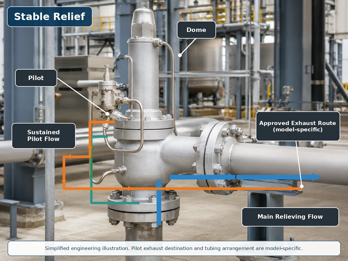
Ilustração de engenharia simplificada baseada em uma instalação real de válvula. O suprimento real do piloto, o domo e os caminhos de exaustão são específicos do modelo.
Caminho do fluxo durante o alívio da válvula principal
Durante o alívio, o fluxo contínuo do piloto pode ventilar ou regular a pressão do domo. Confirme a base do fluxo do piloto, o destino da exaustão e as consequências do serviço, em vez de tratar o fluxo como um desqualificador automático.
Exaustão do piloto e repressurização do domo
Confirme se a exaustão vai para a atmosfera, a saída ou outro sistema aprovado, e se a pressão de saída, condensado, drenagem, aquecimento ou winterização afetam isso.
O que é um piloto sem fluxo?
Um piloto sem fluxo atinge uma condição estável na qual o fluxo contínuo do meio de processo através do piloto para, enquanto a válvula principal pode permanecer aberta. Os assentos internos, elementos de realimentação e detalhes de controle do domo permanecem específicos do modelo. Manual da série 800 da Emerson descreve essa condição de alívio estável e também observa fluxo transitório quando o piloto muda a abertura.

Ilustração técnica simplificada. Sem fluxo contínuo não significa fluxo transiente zero, vazamento zero ou emissões zero.
Atuação Transiente e Despressurização do Domo
Na pressão de ajuste, o piloto reduz a pressão do domo; uma pequena quantidade do meio do domo ou do processo pode passar durante essa transição.
Alívio Estável Sem Fluxo Contínuo do Piloto
Na abertura estável, o piloto pode isolar a alimentação e a exaustão, interrompendo o fluxo contínuo do piloto. Isso pode reduzir o consumo sustentado do meio, mas não comprova vazamento zero nem elimina os riscos de contaminação e congelamento.
Reajuste e Recarga do Domo
Quando a pressão cai, o caminho de alimentação do domo é reaberto e ocorre um fluxo transiente de recarga antes do fechamento da válvula principal.
Comparação entre Piloto com Fluxo e Piloto sem Fluxo
Role horizontalmente para revisar todas as colunas.
| Fator de Engenharia | Piloto com Fluxo | Piloto sem Fluxo | Pergunta sobre Seleção |
|---|---|---|---|
| Fluxo piloto estável durante o alívio | Normalmente mantido durante a fase de controle relevante. | Normalmente ausente na abertura estável da válvula principal. | O que mostra o esquema operacional selecionado? |
| Fluxo piloto transitório | Presente. | Presente durante o movimento do piloto ou controle da câmara. | Qual volume e rota de exaustão se aplicam? |
| Perda de meio de processo | Pode ser maior através do piloto durante alívio sustentado. | Geralmente menor através do piloto em alívio estável. | O meio é perigoso, valioso ou controlado? |
| Emissões atmosféricas | Possível se a exaustão do piloto estiver aberta para a atmosfera. | Ainda possível durante a atuação se ventilado abertamente. | Onde termina a exaustão do piloto? |
| Exposição a contaminantes | Depende do caminho contínuo, restrições e filtragem. | Depende dos assentos, passagens, fluxo transitório e filtragem. | O meio é adequado para o piloto selecionado? |
| Congelamento e formação de gelo | A expansão contínua pode ser relevante. | A expansão transitória e linhas de detecção úmidas ainda podem congelar. | Qual temperatura mínima e condição de umidade se aplicam? |
| Exposição à contrapressão | O roteamento da exaustão pode afetar o controle do piloto. | O roteamento da exaustão também pode afetar o controle do piloto. | A exaustão do piloto está conectada à saída? |
| Ação de abertura total ou modulante | Classificação separada. | Classificação separada. | Qual ação da válvula principal é necessária? |
| Capacidade de alívio | Não determinado pelo tipo de fluxo do piloto. | Não determinado pelo tipo de fluxo do piloto. | A capacidade documentada é adequada para o caso de alívio? |
Fluxo vs. Não Fluxo Não É o Mesmo que Abertura Total vs. Modulante
O fluxo do piloto, a ação da válvula principal, a localização do sensor e o destino da exaustão do piloto são decisões independentes. Um piloto com fluxo não é automaticamente de ação de abertura total, e um piloto sem fluxo não é automaticamente modulante. Especificação 2900-40 da Baker Hughes fornece exemplos específicos de produtos de pilotos sem fluxo com ação de abertura total e sem fluxo com ação modulante; Visão geral do POSV da LESER explica separadamente o comportamento de abertura total e modulante.
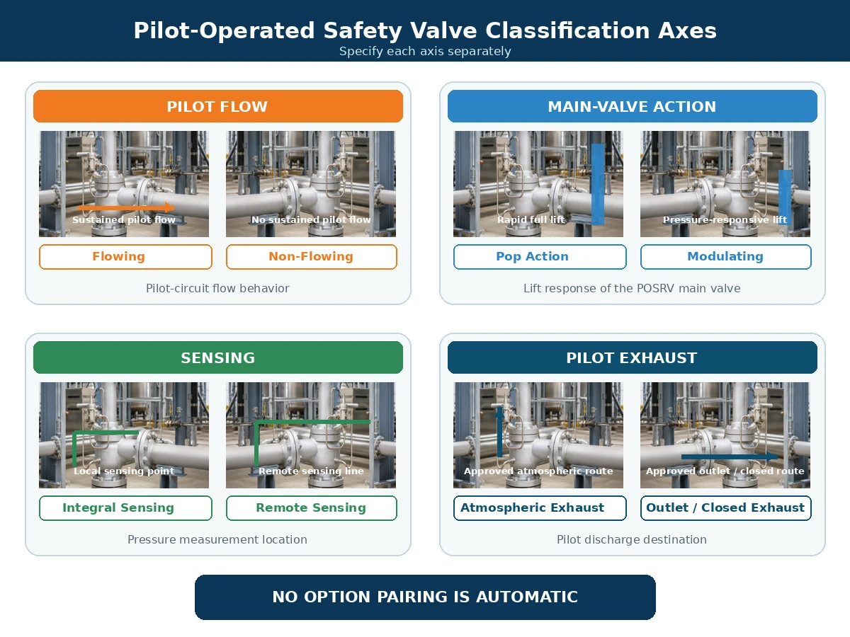
Comparação simplificada de engenharia. As combinações disponíveis dependem do fabricante e da série de produtos selecionados.
Role horizontalmente para revisar todas as colunas.
| Eixo de classificação | Opções Típicas | O que Descreve | O que não descreve |
|---|---|---|---|
| Fluxo do piloto | Com fluxo / sem fluxo | Comportamento do meio de processo através do circuito piloto. | Característica de abertura da válvula principal. |
| Ação da válvula principal | Abertura total / modulante | Abertura total rápida ou abertura proporcional à pressão. | Se o fluxo piloto é contínuo. |
| Disposição de sensoriamento | Integral / remoto | Onde o piloto mede a pressão do sistema protegido. | Destino da exaustão do piloto. |
| Disposição da exaustão | Atmosfera / saída / rota fechada aprovada | Onde o meio do piloto é descarregado. | Ação da válvula principal ou capacidade de alívio. |
Como a Exaustão do Piloto e a Contrapressão Afetam a Decisão
Exaustão Atmosférica vs. Exaustão na Saída
A exaustão atmosférica do piloto pode ser inaceitável para meios tóxicos, inflamáveis, corrosivos, odoríferos, ambientalmente controlados ou valiosos. Direcionar a exaustão para a saída da válvula principal pode reduzir a liberação atmosférica local, mas pode expor a conexão de exaustão do piloto à pressão de saída.
Contrapressão sobreposta e contrapressão acumulada
A contrapressão superimposta existe antes da abertura da válvula. A contrapressão acumulada se desenvolve devido ao fluxo de alívio através do sistema de saída após a abertura. Qualquer condição pode afetar o equilíbrio de forças da válvula principal, a exaustão do piloto, a redução da pressão da câmara, a abertura, o re-assentamento e o refluxo. Revise esses efeitos com o guia da ZOBAI sobre Contrapressão e fole.
Role horizontalmente para revisar todas as colunas.
| Condição | Dados Necessários | Questão do circuito piloto | Limite de decisão |
|---|---|---|---|
| Contrapressão sobreposta constante | Pressão de saída antes da abertura. | Atua na exaustão, na válvula principal ou em ambas? | Confirme o limite do modelo e a base de capacidade. |
| Contrapressão sobreposta variável | Perfil de pressão de saída mínimo, normal e máximo. | A variação pode alterar a abertura, o levantamento, a estabilidade ou o reassentamento? | Não aprove com base em um único valor médio. |
| Contrapressão acumulada | Cálculo do sistema de descarga na vazão de alívio governante. | Pode restringir a exaustão do piloto ou reduzir o desempenho da válvula principal? | Avalie na vazão necessária, não na operação normal. |
| Exaustão do piloto conectada à saída principal | Pressão de saída durante a abertura, o alívio e o reassentamento. | Como são afetados o alívio de pressão do domo e o rearme? | Exigir o esquema de exaustão aprovado. |
| A pressão de saída pode exceder a pressão de entrada ou do domo | Diferencial reverso plausível e sequência de operação. | É necessária prevenção de refluxo ou outro controle? | Não presuma que o arranjo padrão do piloto evite o fluxo reverso. |
Proteção contra refluxo e circuito piloto
Se a pressão de saída exceder a pressão de entrada ou do domo, o meio de descarga pode entrar no domo ou no circuito piloto, ou criar uma força de abertura não intencional na válvula principal. Os controles específicos do fabricante podem incluir dispositivos de retenção, prevenção de refluxo e arranjos de exaustão aprovados.
Riscos de meio, temperatura e contaminação
Gás e vapor limpos
Gás seco limpo reduz algumas preocupações de drenagem e incrustação, mas a composição, a temperatura de expansão, as vedações e a classificação de exaustão ainda exigem revisão.
Condensação, formação de gelo e hidratos
Umidade, passagens pequenas e pontos baixos podem criar condensação, formação de gelo ou hidratos. A operação sem fluxo não elimina os requisitos de drenagem e proteção contra o inverno.
Meios sujos ou solidificantes
Ferrugem, incrustação, partículas, cera e depósitos podem restringir os componentes do piloto. Os filtros devem ser adequados, acessíveis e mantidos.
Temperatura e medidas auxiliares
Revise todos os componentes afetados do piloto e da válvula principal, não apenas o material do corpo: partes molhadas, bocal, disco, guia, tubulação, mola, sede/vedação, diafragma e qualquer fole usado na configuração selecionada da válvula principal. Montagem remota, aquecimento, resfriamento ou materiais diferentes podem ser necessários.
Role horizontalmente para revisar todas as colunas.
| Meio ou condição | Risco do sistema piloto | Itens a confirmar | Quando não prosseguir sem revisão |
|---|---|---|---|
| Gás ou vapor seco e limpo | Resfriamento por expansão, vedações e exaustão perigosa ainda importam. | Corpo do piloto, tubulação, sedes, vedações, temperatura mínima e rota de exaustão. | Quando a composição, a temperatura de alívio ou a classe de exaustão forem desconhecidas. |
| Gás úmido ou vapor condensável | Condensado, formação de gelo, hidratos e caminhos de detecção bloqueados. | Roteamento com autodrenagem, pontos baixos, drenos, aquecimento e localização do filtro. | Quando as linhas de detecção e exaustão não podem ser drenadas ou protegidas contra o inverno. |
| Meio sujo ou com partículas | Restrições bloqueadas, sedes danificadas, filtros obstruídos e contaminação da câmara. | Características das partículas, filtração, tamanho da passagem e acesso para manutenção. | Quando a adequação ou uma estratégia de proteção mantível não está documentada. |
| Meio corrosivo | Ataque ao corpo do piloto, tubulação, partes internas molhadas, sedes e vedações macias. | Materiais, tubulação, compatibilidade de sede/vedação e registros. | Quando a revisão é baseada apenas no material do corpo da válvula principal. |
| Serviço com polimerização, cristalização ou solidificação | Obstrução, passagens bloqueadas, depósitos e controle prejudicado da câmara. | Controle de temperatura, purga/lavagem, pontos mortos e base de manutenção. | Quando depósitos podem se formar em passagens inacessíveis. |
| Serviço em alta ou baixa temperatura | Mola piloto, sedes, vedações, diafragma, tubulação e filtros podem apresentar temperaturas diferentes do corpo principal. | Temperaturas de operação e alívio, extremos ambientes, montagem remota, arranjos de aquecimento ou resfriamento. | Quando apenas a classificação de temperatura do corpo da válvula principal foi verificada. |
| Serviço com líquido, flashing ou duas fases | Resposta dinâmica, base de capacidade e estabilidade do piloto podem diferir do serviço com gás. | Base exata de fase, condições de alívio e aprovação explícita do fabricante. | Quando a fase é assumida em vez de calculada ou confirmada. |
Controles de Instalação: O Que Fazer e O Que Evitar
A arquitetura do piloto só pode funcionar como pretendido quando a entrada, saída, linha de sensoriamento, tubulação do domo e exaustão do piloto da válvula principal são instalados como um sistema integrado de proteção contra pressão. Para controles detalhados de entrada, saída, suporte e linha de sensoriamento, use o guia de instalação de válvulas de segurança.
Fazer
- Mantenha a entrada da válvula principal curta e direta e avalie a perda de pressão na entrada para o caso de alívio governante.
- Apoie a tubulação de saída de forma independente e revise a força de reação da descarga, o movimento térmico e as cargas no coletor.
- Direcione as linhas de sensoriamento remoto para minimizar perda de pressão, pulsação, acúmulo de líquido e isolamento acidental.
- Apoie a tubulação do piloto e preserve o diâmetro interno, as conexões e os pontos de ligação exigidos pelo fabricante.
- Direcione a exaustão do piloto para um destino seguro aprovado e avalie a pressão imposta nesse trajeto.
- Forneça drenagem, aquecimento, isolamento ou proteção ambiental quando o serviço e as instruções do fabricante assim o exigirem.
- Mantenha respiros, drenos, filtros, conexões de teste e juntas de manutenção acessíveis.
Não Faça
- Não conecte a linha de sensoriamento a um ponto arbitrário nem presuma que a pressão de saída seja a pressão do sistema protegido.
- Não adicione válvulas de isolamento às linhas de sensoriamento ou do piloto sem um arranjo aprovado, travado ou controlado.
- Não reduza o tamanho da tubulação, adicione trechos longos sem suporte ou crie pontos baixos sem revisar o efeito na resposta.
- Não bloqueie, tampe ou combine um respiro ou dreno do piloto, a menos que o projeto selecionado permita explicitamente o arranjo.
- Não deixe que a válvula principal suporte o peso ou a carga de reação de tubulação de descarga pesada.
- Não trate o traço térmico, a purga ou os filtros como soluções universais para um meio inadequado.
- Não altere o roteamento de exaustão sem verificar a contrapressão, a área classificada e os requisitos ambientais.
Ponto de parada para inspeção: Qualquer alteração na localização do sensor, na tubulação do piloto, no roteamento de exaustão, no coletor de saída ou na filosofia de isolamento exige uma revisão específica do fabricante e do projeto antes da comissionamento.
Modos de falha comuns e verificações de manutenção
Role horizontalmente para revisar todas as colunas.
| Sintoma Observado | Possível causa no circuito do piloto | Outra causa possível | Verificação obrigatória |
|---|---|---|---|
| A válvula principal abre tarde | Linha de sensor ou entrada do piloto bloqueada. | Medição de pressão incorreta ou problema de pressão de ajuste. | Verifique o roteamento do sensor e os dados de teste calibrados. |
| A válvula principal abre cedo | Vazamento no assento do piloto ou ajuste incorreto do piloto. | Pulsação de pressão ou ponto de sensoriamento inadequado. | Inspecione o piloto e a fonte de pressão. |
| A válvula principal não atinge a elevação esperada | Exaustão do piloto restrita ou despressurização inadequada do domo. | Fluxo de processo insuficiente ou contrapressão excessiva. | Revise a exaustão do piloto e o sistema instalado. |
| A válvula principal cicla | Instabilidade do piloto ou pulsação na linha de sensoriamento. | Superdimensionamento, perda na entrada ou contrapressão variável. | Revise o sistema de alívio completo. |
| Reassentamento lento | Caminho de recarga do domo restrito. | Atrito na válvula principal ou blowdown inadequado. | Inspecione o piloto e a válvula principal. |
| O respiro piloto congela | Meio úmido e resfriamento por expansão. | Exposição ambiente ou drenagem inadequada. | Revise o controle de umidade e a proteção para o inverno. |
Não diagnostique apenas pelo sintoma. Uma válvula com ciclagem, abertura tardia ou baixa elevação pode ser causada pelo circuito piloto, mas também pode resultar de perda de pressão na entrada, superdimensionamento da válvula, fluxo de processo insuficiente, contrapressão variável, atrito na válvula principal ou local de sensoriamento inadequado. Preserve os registros de pressão, a condição do piloto, a configuração da tubulação e as evidências de teste antes de alterar o ajuste do piloto.
A manutenção deve seguir um procedimento aprovado de isolamento, despressurização e teste. Não bloqueie os respiros ou drenos do piloto, não altere a tubulação sem preservar o projeto exigido, nem infira a capacidade de alívio a partir de um teste de pressão de ajuste.
Um Fluxo de Trabalho de Decisão para Selecionar a Arquitetura do Piloto
1. Defina o Caso de Alívio
- Equipamento protegido e cenário de sobrepressão governante; use o Sistemas de alívio de pressão API 521 guia onde a base do projeto adota a API 521
- Pressão de operação, MAWP ou pressão de projeto e pressão de ajuste
- Sobrepressão admissível e acumulação
- Capacidade de alívio necessária e base de cálculo
- Pressão de alívio, temperatura de alívio, meio e fase
2. Definir os requisitos de fluxo piloto e exaustão
- Se o fluxo piloto contínuo é aceitável
- Requisito de exaustão atmosférica, de saída ou fechada
- Ação de abertura total ou modulante
- Sensoriamento integral ou remoto
- Requisitos de prevenção de refluxo e teste em campo
3. Revisar os riscos de serviço e falha
- Contaminação, corrosão e solidificação
- Condensação, congelamento e formação de hidratos
- Vibração, pulsação e arranjo da linha de sensoriamento
- Exposição ambiental e acesso para manutenção
4. Confirme o projeto específico do fabricante
- Esquema de operação do piloto e folha de dados do modelo
- Limites de pressão, temperatura, fase e contrapressão
- Materiais, vedações, filtros, drenos e aquecedores
- Capacidade documentada e documentos de projeto necessários
Quando esta comparação não é suficiente
Não selecione uma válvula apenas com base na comparação de fluxo/não fluxo quando qualquer um dos seguintes itens permanecer sem solução:
- O equipamento protegido ou o cenário de alívio governante não foi identificado.
- A capacidade de alívio necessária, a pressão de alívio, a temperatura de alívio ou a base de fase estão ausentes.
- A contrapressão superimposta ou acumulada é variável, desconhecida ou afetada por um coletor comum.
- O meio pode congelar, polimerizar, cristalizar, corroer, incrustar ou transportar sólidos.
- São necessários sensoriamento remoto, exaustão fechada do piloto, prevenção de refluxo ou teste em campo.
- O esquema original do piloto, o roteamento de exaustão ou a fonte de sensoriamento da válvula de reposição não estão disponíveis.
- O fabricante selecionado não confirmou o serviço, os materiais, a ação do piloto e os acessórios.
Regra de decisão: Quando uma entrada ausente pode alterar a capacidade, a estabilidade do piloto, a segurança da exaustão, a compatibilidade de materiais ou a aceitação do código, registre-a como “A Confirmar” em vez de convertê-la em um fato presumido.
Cenários de Engenharia Compostos
Os cenários a seguir são exemplos compostos de treinamento. Eles não representam clientes nomeados, incidentes verificados ou projetos concluídos da ZOBAI.
Gás Limpo de Alta Pressão com Emissões Atmosféricas Restritas
Problema observado: Um RFQ especifica “fluxo não contínuo necessário” apenas porque as emissões atmosféricas locais são restritas. Causa de engenharia: A solicitação trata o fluxo estável do piloto como se fosse o único caminho de liberação possível. Correção: Compare a exaustão transitória do piloto, o fluxo estável do piloto, a descarga da válvula principal, o roteamento da exaustão, a contrapressão e a capacidade documentada. Prevenção: Exija o esquema do piloto selecionado e um destino de exaustão aprovado antes da aprovação do modelo.
Gás Úmido com Risco de Condensação e Congelamento
Problema observado: Um piloto de gás úmido responde lentamente ou fica instável durante baixa temperatura ambiente. Causa de engenharia: A umidade se acumula nos pontos baixos de detecção ou exaustão e congela durante a redução de pressão. Correção: Restabelecer o roteamento de autodrenagem e aplicar o arranjo de drenagem, aquecimento ou proteção para inverno aprovado pelo fabricante. Prevenção: Confirmar a temperatura mínima, condição de umidade, roteamento da linha, filtros e acesso para manutenção durante a revisão do projeto.
Válvula de substituição com roteamento de exaustão do piloto não confirmado
Problema observado: Uma POSRV de substituição corresponde aos tamanhos de flange e à pressão de ajuste, mas não reproduz o comportamento operacional original. Causa de engenharia: O tipo original do piloto, a fonte de sensoriamento, a rota de exaustão, a base de capacidade ou a condição de contrapressão não foram verificados. Correção: Reconstruir a base de alívio e comparar o esquema operacional completo e a capacidade documentada. Prevenção: Controlar as substituições por meio de gestão de mudanças, desenhos aprovados, registros de teste, dados de placa de identificação e rastreabilidade.
Fluxo de trabalho de verificação de substituição
Uma válvula de segurança pilotada não deve ser substituída apenas pela correspondência de aparência, tamanho de entrada, tamanho de saída e pressão de ajuste.
Reconstruir a base de proteção contra pressão
Confirmar o equipamento protegido, o cenário de alívio governante, a MAWP ou pressão de projeto, a pressão de ajuste, a sobrepressão permitida, a capacidade necessária e as condições de alívio.
Identificar a arquitetura original do piloto
Obter a folha de dados original, a placa de identificação, o esquema operacional e as instruções de manutenção. Confirmar se é de fluxo contínuo ou não, pop ou modulante, fonte de sensoriamento e rota de exaustão.
Verifique as conexões instaladas
Trace a alimentação do piloto, a linha do domo, a linha de sensoriamento, a exaustão, os drenos, os filtros, os aquecedores, as conexões de teste e quaisquer dispositivos de prevenção de refluxo.
Compare as condições reais de serviço
Revise o meio, a fase, a contaminação, as temperaturas de operação e de alívio, a contrapressão superimposta e acumulada, as condições ambientais e os requisitos de exaustão perigosos.
Verifique a capacidade e a resposta à pressão separadamente
Corresponda a capacidade necessária à capacidade documentada da válvula proposta e confirme a pressão de ajuste, o blowdown e o tipo de ação com base no projeto.
Aprove as diferenças de instalação
Não altere o ponto de sensoriamento, a tubulação, a exaustão do piloto, a disposição da saída, os materiais ou os acessórios sem revisão documentada.
Defina as evidências de teste e liberação
Acorde sobre o teste de pressão de ajuste, a estanqueidade do assento, as verificações funcionais, os registros de materiais, as evidências de capacidade, os desenhos, os manuais e a liberação de inspeção antes do envio ou comissionamento.
O que os compradores devem colocar na folha de dados e no RFQ
Especificar apenas “válvula de segurança pilotada”, tamanho de entrada e pressão de ajuste não é suficiente. O fornecedor precisa de requisitos completos de processo, alívio, circuito piloto e documentação.
Lacuna comum no RFQ: As solicitações frequentemente identificam “pilotada”, pressão de ajuste e tamanho da conexão, mas omitem o cenário de alívio, a capacidade necessária, a temperatura de alívio, a contrapressão, a fonte de sensoriamento e o destino do escape da piloto. Essas omissões devem interromper a confirmação do modelo, em vez de serem preenchidas por suposição.
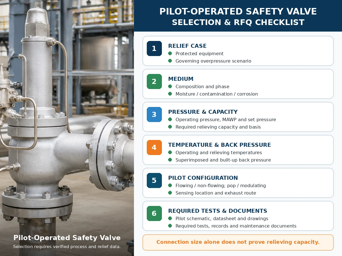
Apenas lista de verificação de engenharia. A seleção final do modelo depende de dados de processo verificados, informações do fabricante, normas aplicáveis e revisão do projeto.
Role horizontalmente para revisar todas as colunas.
| Entrada Necessária | Por que Importa | Status |
|---|---|---|
| Equipamento protegido e cenário de alívio dominante | Define o dever de proteção contra pressão e a carga necessária. | A confirmar |
| Fluido, composição e fase | Afeta a piloto, vedações, manuseio do escape e base de capacidade. | A confirmar |
| Pressão de operação, pressão máxima de projeto (MAWP)/pressão de projeto e pressão de ajuste | Define a margem operacional e o limite de pressão. | A confirmar |
| Sobrepressão admissível e acumulação | Afeta o dimensionamento e a base de alívio aplicável. | A confirmar |
| Capacidade de alívio necessária e base de cálculo | Determina a capacidade documentada necessária da válvula. | A confirmar |
| Temperaturas de operação e de alívio | Controla materiais, vedações, arranjo da piloto e base de capacidade. | A confirmar |
| Contrapressão sobreposta e acumulada | Afeta o comportamento da válvula principal e do escape da piloto. | A confirmar |
| Com fluxo/sem fluxo, pop/modulante, sensoriamento e exaustão | Define quatro decisões separadas do sistema piloto. | A confirmar |
| Materiais, filtragem, aquecimento, drenagem e acesso para manutenção | Aborda a compatibilidade de serviço e os controles de falha. | A confirmar |
| Código aplicável, testes e documentos | Define o pacote de evidências do projeto. | A confirmar |
Matriz de teste e documentação
Os testes e a documentação devem mostrar diferentes partes da cadeia de evidências de proteção contra pressão. Um relatório de teste não deve ser usado para reivindicar resultados que ele não estabelece.
Role horizontalmente para revisar todas as colunas.
| Teste ou Documento | O que Pode Suportar | O que não prova por si só | Verificação de RFQ |
|---|---|---|---|
| Teste de pressão de ajuste do piloto ou da válvula montada | Resposta de abertura sob o procedimento declarado. | Capacidade, resposta à contrapressão de campo ou compatibilidade do processo. | Especificar meio, procedimento, critério de aceitação e formato do relatório. |
| Teste de estanqueidade do assento / Teste de estanqueidade de sede API 527 orientação quando aplicável | Vazamento sob as condições e critérios declarados. | Vazamento zero em todos os serviços ou condições de operação. | Especificar método, pressão de teste, meio e critérios de aceitação. |
| Teste funcional do piloto/válvula principal | Atuação do piloto, controle do domo, movimento da válvula principal e rearme. | Capacidade total em campo ou desempenho do coletor de descarga não testado. | Confirmar arquitetura, tipo de ação e acessórios incluídos. |
| Tabela de capacidade, certificado ou registro de cálculo | Desempenho de alívio documentado para o projeto selecionado. | Adequação para uma fase, temperatura, contrapressão ou meio diferente. | Corresponder modelo, orifício, base de fluido e evidência necessária. |
| Arranjo geral e esquema operacional do piloto | Conexões, caminhos de fluxo, sensoriamento, exaustão e acessórios. | Compatibilidade de materiais ou capacidade, salvo se documentado separadamente. | Exigir a revisão do desenho utilizada para fabricação e instalação. |
| Registros de materiais | Identidade do material especificada para componentes listados de retenção de pressão e molhados. | Adequação à corrosão sem revisão de material específica do serviço. | Definir quais componentes e nível de rastreabilidade são necessários. |
| Folha de dados, placa de identificação e liberação de inspeção. | Configuração, pressão de ajuste, identificação do modelo e status de inspeção acordado. | Um cálculo de alívio completo ou certificação universal. | Verificar consistência entre pedido de compra, desenho, relatórios de teste e placa de identificação final. |
| Instruções de instalação e manutenção | Orientação aprovada para tubulação, sensoriamento, exaustão, teste, manutenção e peças sobressalentes. | Aprovação do projeto quando a disposição instalada diferir das instruções. | Inclua a revisão exata da série do produto no pacote de documentos. |
Registros de reparo e reajuste: Quando exigido pelo programa de reparo aplicável ou pela especificação do projeto, retenha os dados de pressão de ajuste e estanqueidade do assento como encontrado e como deixado, registros de peças de reposição, controles de re-selagem ou de placa de identificação, rastreabilidade e aprovação de gestão de mudanças. A orientação de estanqueidade do assento da API 527 não substitui o dimensionamento ou a verificação da capacidade documentada.
Normas e notas de fonte
As evidências operacionais específicas do fabricante estão vinculadas ao lado das declarações relevantes de fluxo, não fluxo e pop/modulação acima. Esses documentos suportam apenas as famílias de produtos identificadas e não devem ser tratados como dados de desempenho universais de POSRV.
- API 520 Parte I, 10ª Edição — aviso oficial de publicação de dimensionamento e seleção da API.
- API 520 Parte II, 7ª Edição — aviso oficial de publicação de instalação da API.
- ASME BPVC Seção XIII, Edição 2025 — regras para proteção contra sobrepressão.
- ISO 4126-4:2013 — válvulas de segurança pilotadas; a ISO lista a publicação como revisada e confirmada em 2025.
Essas referências têm escopos diferentes. Confirme a edição adotada pelo projeto, o código do equipamento protegido, a jurisdição, o escopo do fabricante/modelo e a documentação exigida. Um nome de norma não é prova de que todos os modelos ZOBAI possuem todas as certificações.
Perguntas Frequentes
Qual é a diferença entre uma válvula de segurança pilotada com fluxo e sem fluxo?
Um piloto com fluxo mantém um caminho de piloto projetado durante o estado de alívio estável relevante. Um piloto sem fluxo interrompe o fluxo contínuo do piloto em uma condição estável da válvula principal, embora possa ocorrer fluxo transitório durante a atuação e a recarga da câmara.
Um piloto sem fluxo significa que nenhum meio de processo passa pelo piloto?
Nº. O meio pode passar enquanto o piloto atua, altera a pressão da câmara ou repressuriza a câmara. Não-fluxo refere-se à condição estável, não a cada instante.
Um piloto sem fluxo é sempre melhor do que um piloto com fluxo?
Nº. A adequação depende do meio, do trajeto de exaustão, da temperatura, da contaminação, da contrapressão, da capacidade necessária, do tipo de ação e do projeto selecionado do fabricante.
O fluxo contínuo vs. não contínuo é o mesmo que ação de estalo vs. modulante?
Nº. Fluente ou não fluente descreve o fluxo no circuito piloto. Pop ou modulante descreve a resposta de abertura da válvula principal. Especifique-os separadamente.
Para onde vai o escape do piloto?
Dependendo do projeto, a exaustão da piloto pode ir para a atmosfera, para a saída principal ou para outro trajeto fechado aprovado. Confirme o esquema e o efeito da contrapressão.
Qual tipo de piloto é melhor para meios de processo perigosos ou valiosos?
Um projeto sem fluxo contínuo pode reduzir a perda sustentada do meio piloto, mas a exaustão transitória, a descarga principal, os critérios de vazamento, o roteamento e a adequação do modelo ainda exigem revisão.
Um piloto sem fluxo ainda pode sofrer congelamento ou contaminação?
Sim. Linhas de sensoriamento, filtros, restrições, passagens do domo e exaustões podem acumular umidade, congelar ou obstruir. Drenagem, filtração e proteção para inverno permanecem específicas de cada serviço.
Quais informações são necessárias antes de selecionar a arquitetura pilotada?
Informe o equipamento protegido, o cenário de alívio, o meio e a fase, os dados de pressão, a capacidade necessária, a temperatura de alívio, a contrapressão, o sensoriamento, a descarga, a tubulação, os materiais, o tipo de ação e os documentos necessários.
Normas e Limitações de Engenharia
A API 520 Parte I aborda dimensionamento e seleção, enquanto a API 520 Parte II aborda instalação dentro de seus respectivos escopos. A ASME BPVC Seção XIII fornece uma estrutura para proteção contra sobrepressão. A ISO 4126-4 aborda válvulas de segurança pilotadas como norma de produto; não é um código de aplicação para o sistema protegido. Verifique a edição adotada pelo projeto, o código de equipamento aplicável, a jurisdição e os dados específicos do produto do fabricante.
A seleção final depende do equipamento protegido, cenário de alívio governante, meio e fase reais, pressão de operação, MAWP ou pressão de projeto, pressão de ajuste, capacidade de alívio necessária e documentada, temperatura de alívio, contrapressão superimposta e acumulada, tubulação de entrada e saída, todos os materiais afetados e componentes de vedação, configuração do piloto, edição da norma adotada, especificação do projeto e requisitos regulatórios locais aplicáveis.
Solicite uma revisão de engenharia de válvula de segurança pilotada
A escolha final entre válvulas de segurança pilotadas com fluxo e sem fluxo deve seguir o cenário real de alívio, a capacidade necessária, o meio e a fase, a temperatura de alívio, a contrapressão, a disposição de sensoriamento e exaustão, os materiais, a tubulação e a documentação exigida. Envie essas informações antes de solicitar uma recomendação de modelo.