Инженерное сравнение предохранительных клапанов с пилотным управлением

Инженерное сравнение предохранительных клапанов с пилотным управлением
Предохранительные клапаны с пилотным управлением проточного и непроточного типа различаются в основном по контуру пилота при установившемся сбросе давления. Проточная конструкция обычно поддерживает контролируемый сброс или поток; непроточная конструкция обычно прекращает непрерывный поток пилота после того, как основной клапан достигает устойчивого состояния сброса, хотя переходный поток все еще может возникать во время срабатывания, регулировки подъема, посадки и подзарядки сильфона. Это различие важно, когда сброс пилота, выбросы, влага, загрязнение, обледенение, противодавление или длительный сброс влияют на спецификацию. Это не определяет импульсное или модулирующее действие, место отбора давления или пропускную способность. Давление настройки и размер присоединения также не подтверждают, что выбранный клапан имеет достаточную задокументированную пропускную способность. Перед выбором подтвердите защищаемое оборудование, сценарий сброса, среду и фазу, рабочее давление, MAWP или расчетное давление, давление настройки, требуемую пропускную способность, температуру сброса, наложенное и накопленное противодавление, источник отбора давления, место сброса, материалы и требуемые документы. Отправьте эти условия для инженерной проверки.
Проточные и непроточные предохранительные клапаны с пилотным управлением: краткий ответ
Проточный или непроточный тип описывает поведение рабочей среды в контуре пилота. Проточный пилот обычно поддерживает расчетный расход в соответствующем установившемся режиме сброса; непроточный пилот обычно прекращает непрерывный расход через пилот при установившемся подъеме. Ни один из терминов не определяет действие основного клапана, место отбора давления, направление сброса или пропускную способность.
Непроточный пилот может пропускать переходный объем среды при срабатывании, изменении давления в полости или повторном заполнении полости. Его не следует описывать как клапан с нулевым расходом, нулевыми выбросами или не требующий обслуживания.
Рассматривайте выбранную архитектуру в рамках всей предохранительный клапан с пилотным управлением системы, а не рассматривайте классификацию по типу потока пилота как полную спецификацию.
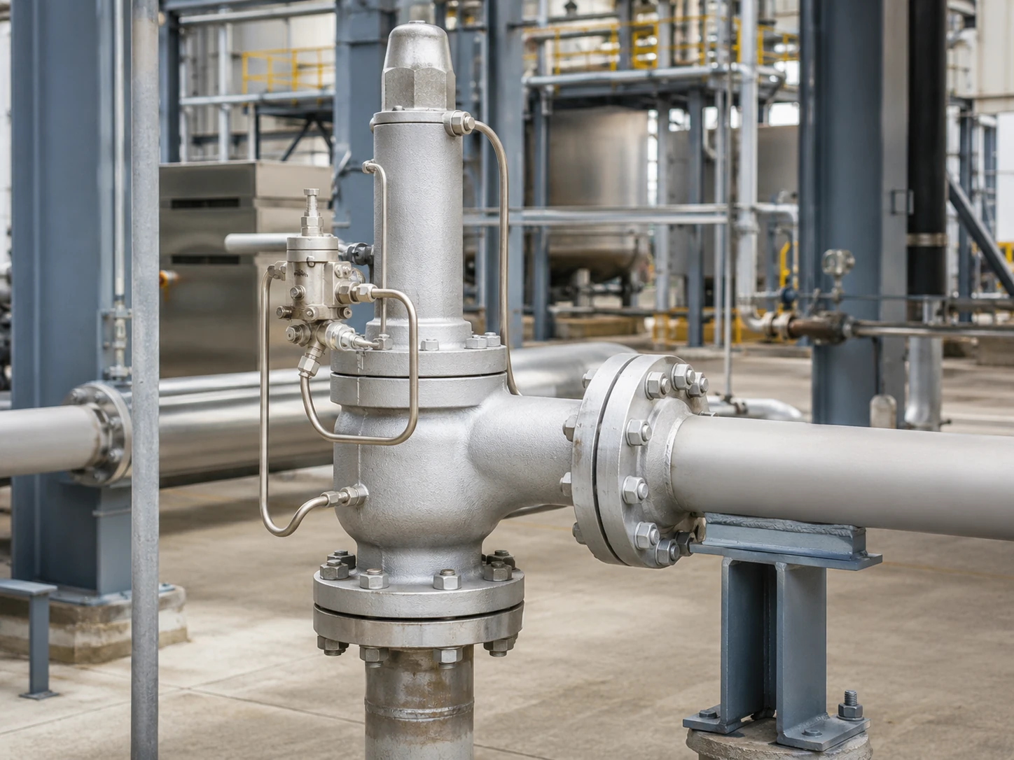
Реалистичная концептуальная визуализация. Фактическая геометрия клапана, отбор давления, трассировка сброса, диапазон давлений и документально подтвержденная пропускная способность должны быть подтверждены для выбранной модели.
Граница выбора: Ни один тип пилота не является универсально лучшим. Архитектура пилота не определяет требуемую пропускную способность, выбранное проходное сечение, допустимое противодавление, совместимость материалов или соответствие нормам. Эти решения требуют анализа конкретного сценария сброса и документации производителя.
Предварительная матрица выбора
Эта матрица является инструментом предварительного отбора, а не рекомендацией по выбору модели. Она определяет вопросы, которые должны быть решены до спецификации проточного или непроточного пилота.
Прокрутите по горизонтали, чтобы просмотреть все столбцы.
| Условия эксплуатации или проекта | Почему это важно | Обзор пилота с протоком | Обзор пилота без протока | Контрольная точка проектирования |
|---|---|---|---|---|
| Ограничен выпуск пилота в атмосферу на месте установки | Вентиляция пилота может быть неприемлема для опасных, ценных или регулируемых сред. | Подтвердите постоянный расход через пилот и согласованный маршрут сброса. | Подтвердите переходный сброс и устойчивое состояние выбранной модели. | Приостановите выбор до определения места сброса и влияния давления на выходе. |
| Сброс давления может быть продолжительным | Длительная продолжительность может увеличить потери среды через пилот и нагрузку на систему сброса. | Запросите данные о рабочем цикле и расходе через пилот. | Подтвердите, когда прекращается непрерывный поток и как контролируется подъем. | Только длительность не определяет конструкцию; решающими остаются пропускная способность и стабильность. |
| Влажный газ, низкая температура окружающей среды или риск гидратообразования | Ограничения, фильтры, импульсные линии и выхлопные тракты могут замерзать или накапливать жидкость. | Проверьте охлаждение при расширении, дренаж, обогрев и температурные пределы. | Проверьте переходные процессы расширения, подзарядку купола и влажные импульсные линии. | Удерживайте до подтверждения контроля влажности и минимальной температуры. |
| Загрязненная, полимеризующаяся или содержащая твердые частицы среда | Малые проходные сечения и седла могут забиваться, залипать или подвергаться эрозии. | Оцените постоянное воздействие на ограничения и фильтры. | Оцените седла, переходные тракты, фильтрацию и загрязнение купола. | Один фильтр не делает среду приемлемой. |
| Переменное давление на выходе или общий выхлопной коллектор | Изменение давления на выходе может повлиять на сброс пилота и баланс сил основного клапана. | Уточните, как давление на выходе воздействует на контур сброса и полости над мембраной. | Подтвердите стабильность сброса, возврат в исходное положение и поведение при обратном потоке. | Разделите внешнее и наведённое противодавление. |
| Требуется дистанционное измерение давления. | Трассировка импульсной линии, потери давления, пульсация, дренаж и изоляция могут влиять на работу. | Подтвердите совместимость дистанционного сигнала с выбранной схемой пилота. | Подтвердите управление в куполе и переходные характеристики при дистанционном измерении давления. | Не делайте вывод о пригодности дистанционного измерения на основе классификации потока пилота. |
| Возможна работа с жидкостью, вскипающей жидкостью или двухфазной средой. | Фазовое поведение влияет на пропускную способность, динамику пилота и стабильность сброса. | Требуется явное одобрение производителя для фактической фазы и случая сброса. | Требуется явное одобрение производителя для фактической фазы и случая сброса. | Сравнения только по потоку/отсутствию потока недостаточно. |
Контрольная точка запроса котировки (RFQ): Не преобразовывайте такое требование, как “отсутствие протока”, в окончательный выбор модели, пока не будут известны нагрузка сброса, фаза, температура сброса, противодавление, источник сигнала и место выброса.
Как предохранительный клапан с пилотным управлением управляет главным клапаном
Главный клапан, пилот и давление в камере
Типичная система включает главный клапан сброса, пилот, камеру или камеру управления, линию отбора давления, трубки и выхлоп пилота. При давлении ниже установленного рабочее давление обычно поддерживает давление в камере и усилие закрытия главного клапана.
При установленном давлении пилот изменяет путь давления в камере, чтобы давление на входе могло открыть главный клапан. Когда давление падает до давления закрытия пилота, камера повторно заполняется давлением, и главный клапан садится на седло.
Давление сигнала и выхлоп пилота
Давление может измеряться встроенным или выносным датчиком. Выхлоп пилота может идти в атмосферу, в основной выход или по другому утвержденному закрытому маршруту; ни один из вариантов не определяется классификацией «с протоком» или «без протока».
Работа пилота не заменяет проверку пропускной способности
Реакция на установленное давление не доказывает, что клапан может пропустить расчетную нагрузку сброса. Подтвердите требуемую пропускную способность, выбранное седло и задокументированную пропускную способность отдельно; размер присоединения не является основанием для пропускной способности. См. расчету предохранительных клапанов и сертифицированной пропускной способности.
Требуемая пропускная способность, выбранный клапан и подтверждение — это разные вещи
Архитектура пилота управляет главным клапаном, но не заменяет цепочку выбора пропускной способности. Каждый пункт ниже отвечает на другой инженерный вопрос.
Значения пропускной способности для пара, воздуха или газа, жидкости и двухфазной среды не взаимозаменяемы. Выбранная основа пропускной способности должна соответствовать фактической среде сброса, фазе, давлению, температуре, противодавлению и применимому методу расчета.
Прокрутите по горизонтали, чтобы просмотреть все столбцы.
| Элемент | Что это означает | Требуемые доказательства | Что не доказывает |
|---|---|---|---|
| Требуемая пропускная способность | Нагрузка сброса от определяющего сценария избыточного давления. | Расчетная основа, свойства среды, фаза, давление и температура сброса. | Он не выбирает размер присоединения или тип пилота. |
| Требуемая площадь проходного сечения | Расчетная минимальная эффективная площадь для расчетной основы. | Применимый метод, коэффициенты, противодавление и допущения по среде. | Он не подтверждает, что коммерческое проходное сечение имеет документально подтвержденную пропускную способность. |
| Выбранное проходное сечение или конструкция клапана | Геометрия производителя, выбранная для обеспечения требуемой нагрузки. | Технический паспорт модели, обозначение проходного сечения и документация по пропускной способности. | Он не подтверждает пригодность по температуре, материалу, выхлопу или противодавлению. |
| Документированная или сертифицированная пропускная способность | Опубликованные или задокументированные характеристики при указанных условиях. | Паспорт производительности, сертификат или расчетная запись, требуемые проектом. | Это не заменяет проверку фактической среды и условий сброса. |
| Размер входного и выходного присоединения | Присоединение трубопровода и фланцевое или резьбовое соединение. | Общая компоновка и спецификация соединения. | Только размер присоединения не подтверждает пропускную способность. |
| Испытание на давление срабатывания | Реакция пилота и клапана на давление в соответствии с процедурой испытаний. | Калиброванная запись испытаний и применимые критерии приемки. | Это не является независимым подтверждением производительности на объекте, пригодности для фазы или характеристик противодавления. |
Примечание к инженерному обзору: Запрос, содержащий только давление настройки и размер присоединения, является неполным. Требуемая пропускная способность и ее расчетная основа являются отдельными входными данными и должны рассматриваться как обязательные контрольные точки до подтверждения модели.
Четыре рабочих состояния, которые следует сравнить покупателям
Прокрутите по горизонтали, чтобы просмотреть все столбцы.
| Рабочее состояние | Обзор пилота с протоком | Обзор пилота без протока | Проверка для конкретной модели |
|---|---|---|---|
| Нормально закрытый режим работы | Определите, существует ли предусмотренный контур сброса или циркуляции. | Определите, становится ли контур пилота статическим после наддува купола. | Компоновка питающего, купольного и выпускного седел. |
| Приведение пилота в действие | Определите, как изменяется путь потока пилота. | Определите переходный объем, проходящий через пилот. | Последовательность срабатывания и путь сброса давления из купола. |
| Установившийся сброс давления основным клапаном | Подтвердите, продолжается ли поток через пилот. | Подтвердите, что непрерывный поток пилота прекращается при устойчивом подъеме. | Технологическая схема производителя. |
| Посадка на седло и повторное наддувание купола | Подтвердите, как восстанавливается давление в куполе. | Подтвердите переходный расход подзарядки и сброс пилота. | Реакция давления закрытия, обратного давления и продувки. |
Состояние 1: Нормальная закрытая работа
При давлении ниже установленного проверьте состояние седла пилота, дренаж импульсной линии, состояние фильтра и возможную утечку купола.
Состояние 2: Срабатывание пилота
При установленном давлении пилот ограничивает подачу в купол и снижает давление в куполе. Во время этого перехода обычно происходит некоторый расход через пилот, в том числе в конструкции без постоянного расхода.
Состояние 3: Установившийся сброс через главный клапан
Это состояние разделяет классификации: конструкции с постоянным расходом поддерживают заданный путь пилота, в то время как конструкции без постоянного расхода прекращают непрерывный расход через пилот при стабильном подъеме.
Состояние 4: Посадка и повторное повышение давления в куполе
При падении давления пилот восстанавливает давление в куполе. Пилот без постоянного расхода все еще может пропускать переходный расход подзарядки до закрытия главного клапана.
Что такое пилот с постоянным расходом?
Пилот с постоянным расходом поддерживает заданный путь технологической среды в соответствующем установившемся состоянии сброса. Расход мал по сравнению с основным сбросом, но может иметь значение для токсичных, горючих, коррозионных, ценных или влагосодержащих сред. Основы операционной деятельности Baker Hughes описывают проточные и непроточные пилоты как одну ось классификации.
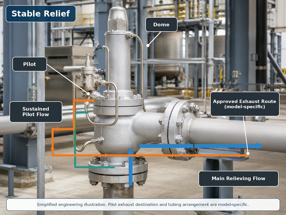
Упрощенная техническая иллюстрация на основе реальной установки клапана. Фактические линии питания пилота, купола и выхлопа зависят от модели.
Путь потока при сбросе давления через главный клапан
Во время сброса давления продолжающийся поток через пилот может стравливать или регулировать давление в куполе. Уточните принцип работы пилота, место сброса выхлопа и последствия для технологического процесса, а не считайте поток автоматическим дисквалифицирующим фактором.
Выхлоп пилота и повторное повышение давления в куполе
Уточните, идет ли выхлоп в атмосферу, в выходной трубопровод или в другую одобренную систему, и влияют ли на него давление на выходе, конденсат, дренаж, обогрев или зимняя изоляция.
Что такое непроточный пилот?
Непроточный пилот достигает стабильного состояния, при котором непрерывный поток рабочей среды через пилот прекращается, в то время как главный клапан может оставаться открытым. Внутренние седла, элементы обратной связи и детали управления куполом зависят от модели. Руководство Emerson Series 800 описывает это состояние стабильного сброса давления, а также отмечает переходный поток, когда пилот изменяет подъем.

Упрощенная техническая иллюстрация. Непроточный не означает нулевой переходный поток, нулевую утечку или нулевые выбросы.
Переходное срабатывание и сброс давления в камере
При давлении уставки пилот снижает давление в камере; небольшое количество среды из камеры или технологической среды может пройти во время этого перехода.
Устойчивый сброс без непрерывного потока через пилот
При устойчивом подъеме пилот может изолировать подачу и сброс, поэтому непрерывный поток через пилот прекращается. Это может снизить постоянный расход среды, но не доказывает нулевую утечку и не исключает риски загрязнения и замерзания.
Сброс и повторное заполнение камеры
При снижении давления путь подачи в камеру снова открывается, и происходит переходный поток повторного заполнения до закрытия основного клапана.
Сравнение проточного и непроточного пилота
Прокрутите по горизонтали, чтобы просмотреть все столбцы.
| Технический параметр | Проточный пилот | Непроточный пилот | Вопрос по выбору |
|---|---|---|---|
| Стабильный расход пилотного потока при сбросе давления | Обычно поддерживается на соответствующем этапе управления. | Обычно отсутствует при стабильном подъеме основного клапана. | Что показывает выбранная принципиальная схема работы? |
| Переходный расход пилота | Присутствует. | Присутствует при перемещении пилота или управлении полостью над поршнем. | Какой объем и путь сброса применяются? |
| Потери рабочей среды | Может быть выше через пилот при продолжительном сбросе. | Обычно ниже через пилот при стабильном сбросе. | Является ли среда опасной, ценной или контролируемой? |
| Выбросы в атмосферу | Возможны, если выхлоп пилота открыт в атмосферу. | Возможно при срабатывании, если выпуск осуществляется открыто. | Куда выводится выхлоп пилота? |
| Воздействие загрязнений | Зависит от непрерывного пути, ограничений и фильтрации. | Зависит от седел, каналов, переходных потоков и фильтрации. | Подходит ли среда для выбранного пилота? |
| Замерзание и обледенение | Непрерывное расширение может быть значимым. | Переходное расширение и влажные импульсные линии все еще могут замерзать. | Каковы минимальная температура и условия влажности? |
| Воздействие противодавления | Маршрутизация выхлопа может влиять на управление пилотом. | Отвод выхлопа также может влиять на пилотное управление. | Подключен ли выхлоп пилота к выходному патрубку? |
| Отрывное или модулирующее действие | Отдельная классификация. | Отдельная классификация. | Какое действие главного клапана требуется? |
| Пропускная способность для сброса | Не определяется типом потока пилота. | Не определяется типом потока пилота. | Достаточна ли задокументированная пропускная способность для случая сброса давления? |
Проточный и непроточный — это не то же самое, что отрывной и модулирующий
Поток пилота, действие главного клапана, место отбора давления и место выхлопа пилота — это независимые решения. Проточный пилот не обязательно является отрывным, а непроточный — модулирующим. Спецификация Baker Hughes 2900-40 содержит примеры как непроточных отрывных, так и непроточных модулирующих пилотов; Обзор POSV от LESER отдельно поясняет поведение подъема с хлопком и модулирующего подъема.
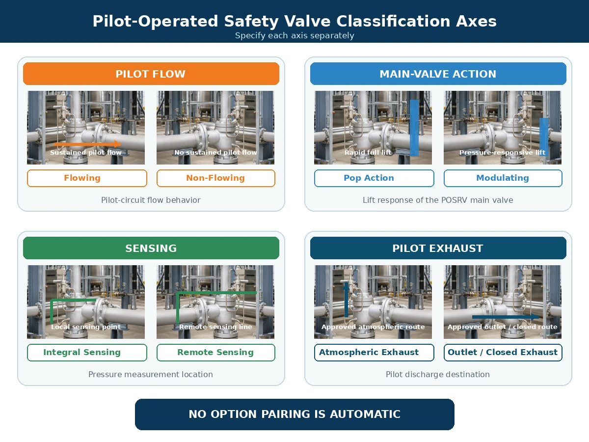
Упрощенное инженерное сравнение. Доступные комбинации зависят от выбранного производителя и серии изделий.
Прокрутите по горизонтали, чтобы просмотреть все столбцы.
| Ось классификации | Типовые варианты | Что описывает | Что она не описывает |
|---|---|---|---|
| Поток пилота | Проточный / непроточный | Поведение рабочей среды через контур пилота. | Характеристика подъема главного клапана. |
| Действие главного клапана | С хлопком / модулирующий | Быстрое полное открытие или подъем, пропорциональный давлению. | Непрерывность пилотного потока. |
| Схема восприятия давления. | Встроенный / дистанционный | Где пилот измеряет давление защищаемой системы. | Место сброса выхлопа пилота. |
| Схема выхлопа | Атмосфера / выходной патрубок / одобренный закрытый трубопровод | Куда сбрасывается рабочая среда пилота. | Действие главного клапана или пропускная способность. |
Как выхлоп пилота и противодавление влияют на выбор
Выхлоп в атмосферу или в выходной патрубок
Выхлоп пилота в атмосферу может быть неприемлем для токсичных, горючих, коррозионных, пахучих, экологически контролируемых или ценных сред. Направление выхлопа в выходной патрубок главного клапана может уменьшить выброс в атмосферу, но может подвергнуть соединение выхлопа пилота воздействию выходного давления.
Наложенное и Накопленное противодавление
Наложенное противодавление существует до открытия клапана. Накапливаемое противодавление возникает из-за потока сброса через выходную систему после открытия. Любое из этих условий может повлиять на силовой баланс главного клапана, выхлоп пилота, снижение давления в куполе, подъем, посадку и обратный поток. Рассмотрите эти эффекты с руководством ZOBAI по противодавление и сильфон.
Прокрутите по горизонтали, чтобы просмотреть все столбцы.
| Условие | Требуемые данные | Вопрос по пилотной цепи | Граничное условие |
|---|---|---|---|
| Постоянное наложенное противодавление | Давление на выходе до открытия. | Действует ли оно на выхлоп, главный клапан или на оба? | Подтвердите предел модели и основу пропускной способности. |
| Переменное наложенное противодавление | Минимальный, нормальный и максимальный профиль давления на выходе. | Может ли изменение повлиять на открытие, подъем, стабильность или посадку? | Не утверждайте по одному среднему значению. |
| Накопленное противодавление | Расчет системы сброса при определяющей скорости сброса. | Может ли оно ограничить выхлоп пилота или снизить производительность главного клапана? | Оценивайте при требуемом расходе, а не при нормальной работе. |
| Выхлоп пилота подключен к основному выходу | Давление на выходе во время открытия, сброса и посадки. | Как влияют сброс давления в куполе и возврат в исходное состояние? | Требуется утвержденная схема сброса. |
| Давление на выходе может превышать давление на входе или в куполе | Достоверный обратный перепад давления и последовательность операций. | Требуется ли защита от обратного потока или другое управление? | Не предполагайте, что стандартная компоновка пилота предотвращает обратный поток. |
Защита от обратного потока и пилотной цепи
Если давление на выходе превышает давление на входе или в куполе, рабочая среда может попасть в купол или пилотную цепь или создать непреднамеренное усилие открытия главного клапана. Средства управления, специфичные для производителя, могут включать обратные устройства, защиту от обратного потока и утвержденные схемы сброса.
Риски, связанные с рабочей средой, температурой и загрязнением
Чистый газ и пар
Чистый сухой газ снижает некоторые проблемы с дренажем и загрязнением, но состав, температура расширения, уплотнения и классификация сброса все еще требуют рассмотрения.
Конденсация, обледенение и гидраты
Влага, малые проходные сечения и нижние точки могут вызывать конденсацию, обледенение или образование гидратов. Режим без протока не отменяет требований к дренажу и зимней эксплуатации.
Загрязненные или застывающие среды
Ржавчина, окалина, частицы, парафин и отложения могут ограничивать подвижность элементов пилота. Фильтры должны быть подходящими, доступными и обслуживаемыми.
Температура и вспомогательные меры
Проверьте все затронутые элементы пилота и основного клапана, не только материал корпуса: смачиваемые детали, сопло, тарелку, направляющую, трубки, пружину, седло/уплотнение, мембрану и любой сильфон, используемый в выбранной конфигурации основного клапана. Могут потребоваться выносной монтаж, обогрев, охлаждение или другие материалы.
Прокрутите по горизонтали, чтобы просмотреть все столбцы.
| Среда или условия | Риски пилотной системы | Что необходимо проверить | Когда не следует действовать без проверки |
|---|---|---|---|
| Чистый сухой газ или пар | Расширительное охлаждение, уплотнения и опасный сброс по-прежнему важны. | Корпус пилота, трубки, седла, уплотнения, минимальная температура и путь сброса. | Если состав, температура сброса или класс сброса неизвестны. |
| Влажный газ или конденсируемый пар | Конденсат, обледенение, гидраты и забитые линии отбора импульса. | Самотечная прокладка линий, нижние точки, дренажи, обогрев и расположение фильтров. | Когда линии отбора импульса и сброса невозможно осушить или защитить от замерзания. |
| Загрязненная среда или среда с твердыми частицами. | Забитые дросселирующие устройства, поврежденные седла, засоренные фильтры и загрязнение полости пилота. | Характеристики частиц, фильтрация, размер проходного сечения и доступ для обслуживания. | Когда пригодность или стратегия защиты с возможностью обслуживания не задокументированы. |
| Агрессивная среда | Воздействие на корпус пилота, трубки, смачиваемые детали, седла и мягкие уплотнения. | Материалы, трубки, совместимость седел/уплотнений и документация. | Когда анализ основан только на материале корпуса основного клапана. |
| Среда, склонная к полимеризации, кристаллизации или затвердеванию. | Залипание, забитые каналы, отложения и нарушение управления полостью пилота. | Контроль температуры, продувка/промывка, тупиковые участки и условия технического обслуживания. | Когда в труднодоступных каналах могут образовываться отложения. |
| Высоко- или низкотемпературная эксплуатация | Пружина пилота, седла, уплотнения, мембрана, трубки и фильтры могут работать при температурах, отличных от температуры основного корпуса. | Рабочие температуры и температуры сброса, экстремальные температуры окружающей среды, дистанционный монтаж, системы обогрева или охлаждения. | Когда проверена только температура корпуса основного клапана. |
| Жидкая среда, среда с вскипанием или двухфазная среда | Динамические характеристики, расчетная пропускная способность и устойчивость пилота могут отличаться от характеристик при работе с газом. | Точный фазовый состав, условия сброса и явное одобрение производителя. | Когда фаза предполагается, а не рассчитывается или подтверждается. |
Монтаж и управление: что делать и чего избегать
Пилотная система может работать должным образом только при условии, что вход, выход, импульсная линия, трубка загрузки и выхлоп пилота основного клапана смонтированы как единая интегрированная система защиты от давления. Для получения подробных требований к входу, выходу, опорам и импульсным линиям используйте руководство по установке предохранительного клапана.
Делать
- Выполняйте подводящий патрубок главного клапана коротким и прямым, а потерю давления на входе оценивайте для определяющего случая сброса.
- Опорно устанавливайте выходной трубопровод независимо и проверяйте реакцию от силы выхлопа, тепловые перемещения и нагрузки на коллектор.
- Прокладывайте линии дистанционного отбора импульса так, чтобы минимизировать потерю давления, пульсацию, образование жидкостных пробок и случайную изоляцию.
- Поддерживайте импульсные трубки пилота и сохраняйте требуемый производителем внутренний диаметр, фитинги и точки подключения.
- Направляйте выхлоп пилота в одобренное безопасное место и оценивайте давление, воздействующее на этот маршрут.
- Обеспечьте дренаж, обогрев, изоляцию или защиту от окружающей среды там, где этого требуют условия эксплуатации и инструкции производителя.
- Обеспечьте доступ к вентиляционным отверстиям, дренажам, фильтрам, контрольным соединениям и обслуживаемым стыкам.
Нельзя
- Не подключайте линию отбора импульса к произвольной точке и не предполагайте, что давление на выходе равно давлению защищаемой системы.
- Не устанавливайте запорные клапаны на линии отбора импульса или пилота без одобренной блокируемой или управляемой схемы.
- Не уменьшайте диаметр трубок, не создавайте длинные неподдерживаемые участки или нижние точки без оценки влияния на срабатывание.
- Не блокируйте, не заглушайте и не объединяйте вентиляцию или дренаж пилота, если выбранная конструкция явно не допускает такую схему.
- Не допускайте, чтобы главный клапан воспринимал вес или реакцию от тяжелого выхлопного трубопровода.
- Не рассматривайте теплоспутники, продувку или фильтры как универсальное решение для неподходящей среды.
- Не изменяйте маршрут выхлопа без проверки противодавления, взрывоопасной зоны и требований к окружающей среде.
Контрольная точка монтажа: Любое изменение места отбора импульса, трубопровода пилота, маршрута выхлопа, выходного коллектора или схемы изоляции требует проверки производителем и по проекту до ввода в эксплуатацию.
Типовые отказы и проверки при техническом обслуживании
Прокрутите по горизонтали, чтобы просмотреть все столбцы.
| Наблюдаемый симптом | Возможная причина в пилотной цепи | Другая возможная причина | Обязательная проверка |
|---|---|---|---|
| Главный клапан открывается с опозданием | Забита линия отбора импульса или вход пилота. | Неправильное измерение давления или проблема с настройкой давления срабатывания. | Проверьте трассу отбора импульса и калиброванные данные испытаний. |
| Главный клапан открывается преждевременно | Утечка в седле пилота или неправильная настройка пилота. | Пульсация давления или неподходящая точка отбора импульса. | Проверьте пилот и источник давления. |
| Основной клапан не достигает ожидаемого подъема | Ограниченный выпуск пилота или недостаточная разгерметизация полости над поршнем. | Недостаточный расход технологической среды или чрезмерное противодавление. | Проверьте пилот и установленную систему. |
| Основной клапан циклирует | Нестабильность пилота или пульсация в импульсной линии. | Завышенный размер, потеря давления на входе или переменное противодавление. | Проверьте всю систему сброса давления. |
| Медленная посадка | Ограниченный путь пополнения полости над поршнем. | Трение основного клапана или неподходящий продувочный дифференциал. | Осмотрите пилот и основной клапан. |
| Замерзание пилотного вентиляционного отверстия | Влажная среда и охлаждение при расширении. | Воздействие окружающей среды или плохой дренаж. | Проверьте контроль влажности и зимнюю защиту. |
Не диагностируйте только по симптому. Циклическое открытие, позднее открытие или малый подъем клапана могут быть вызваны пилотным контуром, но также могут быть результатом потери давления на входе, завышенного размера клапана, недостаточного расхода процесса, переменного противодавления, трения в основном клапане или неподходящего места отбора импульса. Сохраняйте записи давления, состояние пилота, конфигурацию трубопроводов и результаты испытаний перед изменением настройки пилота.
Техническое обслуживание должно выполняться по утвержденной процедуре изоляции, сброса давления и испытаний. Не блокируйте вентиляционные отверстия или дренажи пилота, не изменяйте трубопроводы без сохранения требуемой конструкции и не делайте выводов о пропускной способности по результатам испытания давления срабатывания.
Алгоритм выбора архитектуры пилотного управления
1. Определите случай сброса давления
- Защищаемое оборудование и определяющий сценарий избыточного давления; используйте Системы сброса давления API 521 руководство, если в проекте принят API 521
- Рабочее давление, MAWP или расчетное давление и давление настройки
- Допустимое превышение давления и аккумуляция
- Требуемая производительность сброса и основа расчета
- Давление сброса, температура сброса, рабочая среда и фаза
2. Определите требования к расходу пилота и сбросу
- Допустим ли постоянный расход пилота
- Атмосферный, выходной или закрытый сброс
- Отрывное или модулирующее действие
- Встроенное или дистанционное измерение
- Требования к предотвращению обратного потока и полевым испытаниям
3. Проверьте условия эксплуатации и риски отказов
- Загрязнение, коррозия и затвердевание
- Конденсация, обледенение и образование гидратов
- Вибрация, пульсация и схема импульсных линий
- Воздействие окружающей среды и доступ для обслуживания
4. Подтверждение конструкции, специфичной для производителя
- Принципиальная схема пилотного управления и паспорт модели
- Пределы давления, температуры, фазы и противодавления
- Материалы, уплотнения, фильтры, нагреватели и дренажи
- Документированная пропускная способность и требуемые проектные документы
Когда этого сравнения недостаточно
Не выбирайте клапан только на основе сравнения проточных/непроточных конструкций, если какой-либо из следующих вопросов остается нерешенным:
- Защищаемое оборудование или определяющий сценарий сброса не идентифицированы.
- Отсутствуют требуемая пропускная способность, давление сброса, температура сброса или данные по фазе.
- Наложенное или накопленное противодавление является переменным, неизвестным или зависит от общего коллектора.
- Среда может замерзать, полимеризоваться, кристаллизоваться, вызывать коррозию, загрязнение или содержать твердые частицы.
- Требуются дистанционное управление, закрытый выхлоп пилота, защита от обратного потока или полевые испытания.
- Исходная схема пилота, трассировка выхлопа или источник импульса заменяемого клапана недоступны.
- Выбранный производитель не подтвердил условия эксплуатации, материалы, действие пилота и комплектацию.
Правило принятия решения: Если отсутствующие входные данные могут повлиять на пропускную способность, стабильность пилота, безопасность сброса, совместимость материалов или соответствие нормам, фиксируйте их как “подлежит подтверждению”, а не превращайте в предполагаемый факт.
Комплексные инженерные сценарии
Следующие сценарии являются составными учебными примерами. Они не представляют реальных заказчиков, подтвержденных инцидентов или завершенных проектов ZOBAI.
Чистый газ высокого давления с ограниченными выбросами в атмосферу
Наблюдаемая проблема: В опросном листе указано “непроточный (требуется)” только из-за ограничений на выбросы в атмосферу. Техническая причина: Запрос рассматривает стабильный поток пилота как единственно возможный путь сброса. Коррекция: Сравните переходный сброс пилота, стабильный поток пилота, разряд основного клапана, трассировку сброса, противодавление и задокументированную пропускную способность. Предотвращение: Потребуйте выбранную схему пилота и одобренное место сброса до утверждения модели.
Влажный газ с конденсацией и риском замерзания
Наблюдаемая проблема: Пилот для влажного газа реагирует медленно или становится нестабильным при низкой температуре окружающей среды. Техническая причина: Влага скапливается в нижних точках линии отбора или сброса и замерзает при снижении давления. Коррекция: Восстановите маршрут самодренирования и примените утверждённую производителем схему дренажа, обогрева или зимней защиты. Предотвращение: При проектной проверке подтвердите минимальную температуру, влажностный режим, трассировку линии, фильтры и доступ для обслуживания.
Заменяющий клапан с неподтверждённой трассировкой выхлопа пилота
Наблюдаемая проблема: Заменяющий POSRV соответствует размерам фланцев и давлению настройки, но не воспроизводит исходное рабочее поведение. Техническая причина: Исходный тип пилота, источник импульса, маршрут выхлопа, расчётная пропускная способность или условие противодавления не были проверены. Коррекция: Восстановите расчётную основу сброса и сравните полную принципиальную схему и задокументированную пропускную способность. Предотвращение: Контролируйте замены через управление изменениями, утверждённые чертежи, протоколы испытаний, данные заводской таблички и прослеживаемость.
Рабочий процесс проверки замены
Предохранительный клапан с пилотным управлением не следует заменять только по совпадению внешнего вида, диаметра входа, диаметра выхода и давления настройки.
Восстановите основу защиты по давлению
Подтвердите защищаемое оборудование, определяющий сценарий сброса, MAWP или расчётное давление, давление настройки, допустимое превышение давления, требуемую пропускную способность и условия сброса.
Определите исходную архитектуру пилота
Получите исходный технический паспорт, заводскую табличку, принципиальную схему и инструкции по обслуживанию. Подтвердите тип с протоком или без протока, тип с подрывом или модулирующий, источник импульса и маршрут выхлопа.
Проверьте установленные соединения
Проследите линию питания пилота, линию к куполу, импульсную линию, выхлоп, дренажи, фильтры, нагреватели, контрольные соединения и любые устройства защиты от обратного потока.
Сравните фактические условия эксплуатации
Проверьте среду, фазу, загрязнения, рабочие температуры и температуры сброса, наложенное и накопленное противодавление, условия окружающей среды и требования к опасному выхлопу.
Проверяйте пропускную способность и реакцию по давлению отдельно
Сопоставьте требуемую пропускную способность с документированной пропускной способностью предлагаемого клапана и подтвердите давление настройки, сброс и тип действия в соответствии с проектной основой.
Согласуйте изменения в установке
Не изменяйте точку отбора импульса, трубки, выхлоп пилота, выходное устройство, материалы или аксессуары без документированного рассмотрения.
Определите требования к испытаниям и документам о выпуске
Согласуйте испытания на давление настройки, герметичность седла, функциональные проверки, сертификаты на материалы, данные о пропускной способности, чертежи, руководства и разрешение на отгрузку или ввод в эксплуатацию до отправки или ввода в эксплуатацию.
Что покупатели должны указать в опросном листе и запросе котировок
Указание только “предохранительный клапан с пилотным управлением”, диаметра входа и давления настройки недостаточно. Поставщику необходимы полные требования по процессу, сбросу, пилотной схеме и документации.
Частая ошибка в запросах RFQ: В запросах часто указывают “пилотное управление”, давление настройки и размер присоединения, но не указывают сценарий сброса, требуемую пропускную способность, температуру сброса, противодавление, источник импульса и место сброса выхлопа пилота. Эти пропуски должны останавливать подтверждение модели, а не заполняться предположениями.
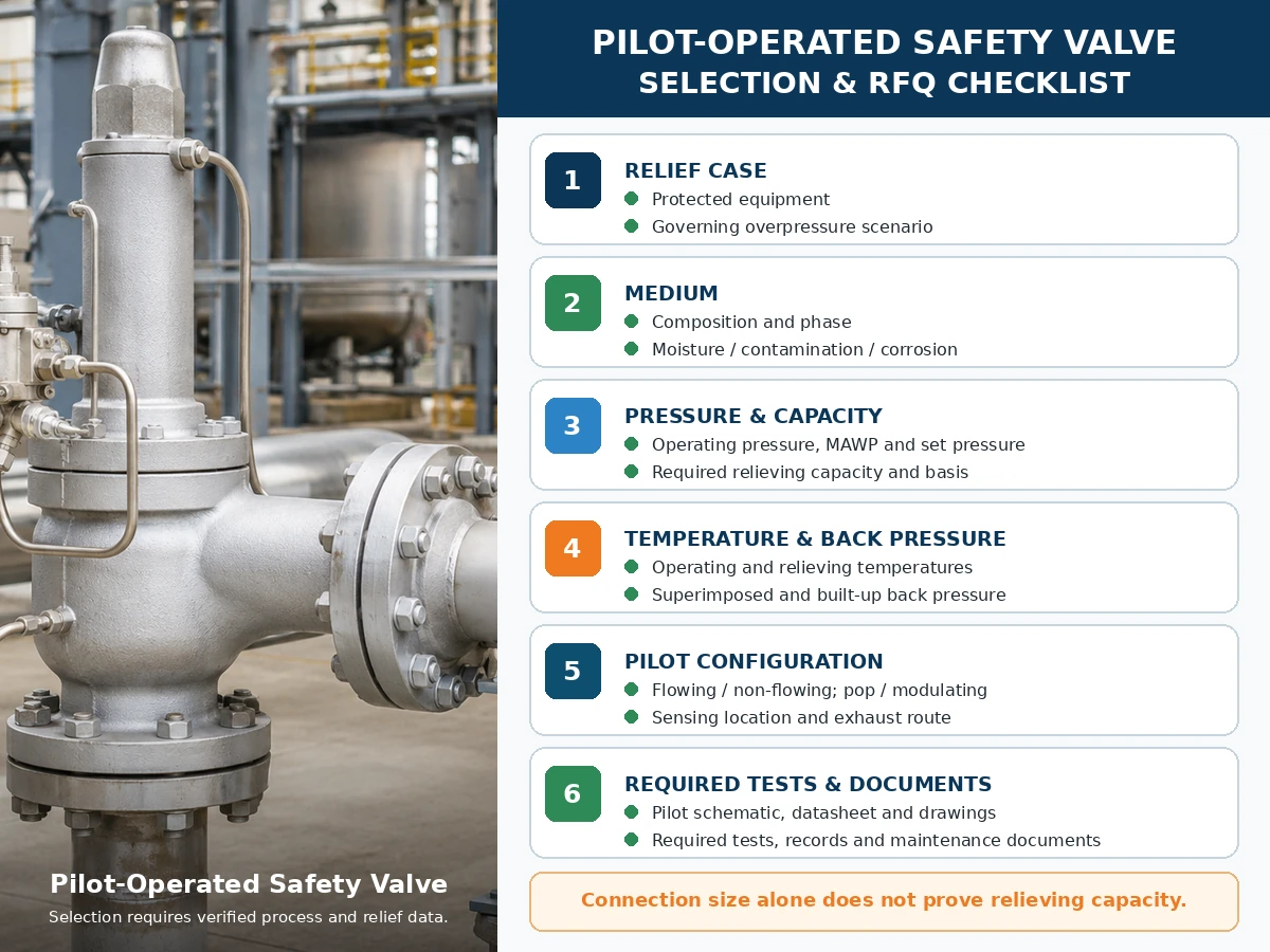
Только инженерный чек-лист. Окончательный выбор модели зависит от проверенных технологических данных, информации производителя, применимых стандартов и проектной экспертизы.
Прокрутите по горизонтали, чтобы просмотреть все столбцы.
| Необходимые входные данные | Почему это важно | Статус |
|---|---|---|
| Защищаемое оборудование и управляющий сценарий сброса | Определяет функцию защиты от давления и требуемую нагрузку. | Требует уточнения |
| Среда, состав и фазовое состояние | Влияет на пилот, уплотнения, обработку выхлопа и основу расчета пропускной способности. | Требует уточнения |
| Рабочее давление, максимальное допустимое рабочее давление (MAWP)/расчетное давление и давление настройки | Определяет рабочий запас и границы давления. | Требует уточнения |
| Допустимое превышение давления и аккумуляция | Влияет на расчет и применимую основу сброса. | Требует уточнения |
| Требуемая производительность сброса и основа расчета | Определяет требуемую документированную пропускную способность клапана. | Требует уточнения |
| Рабочая температура и температура сброса | Определяет материалы, уплотнения, компоновку пилота и основу расчета пропускной способности. | Требует уточнения |
| Наложенное и нарастающее противодавление | Влияет на поведение основного клапана и выхлоп пилота. | Требует уточнения |
| Проточный/непроточный, с хлопком/модулирующий, чувствительный и сбросной | Определяет четыре отдельных решения по системе пилотного управления. | Требует уточнения |
| Материалы, фильтрация, нагрев, дренаж и доступ для обслуживания | Обеспечивает совместимость и контроль отказов. | Требует уточнения |
| Применимые нормы, испытания и документы | Определяет пакет доказательств проекта. | Требует уточнения |
Матрица испытаний и документации
Испытания и документация должны демонстрировать различные части цепочки доказательств защиты от давления. Один отчет об испытаниях не должен использоваться для подтверждения результатов, которые он не устанавливает.
Прокрутите по горизонтали, чтобы просмотреть все столбцы.
| Испытание или Документ | Что он может подтвердить | Что это само по себе не доказывает | Проверка запроса предложения (RFQ) |
|---|---|---|---|
| Испытание давления уставки пилотного или собранного клапана | Реакция на открытие в соответствии с указанной процедурой. | Пропускная способность, реакция на полевое противодавление или совместимость с процессом. | Укажите среду, процедуру, критерии приемки и формат отчета. |
| Испытание на герметичность седла / Испытание на герметичность седел API 527 руководство, где применимо | Утечка при указанных условиях и критериях. | Нулевая утечка во всех средах или условиях эксплуатации. | Укажите метод, испытательное давление, среду и критерии приемки. |
| Функциональное испытание пилота и главного клапана | Срабатывание пилота, управление полостью над поршнем, перемещение главного клапана и возврат в исходное положение. | Полная пропускная способность на площадке или непроверенная производительность выпускного коллектора. | Подтвердите конструкцию, тип действия и входящие в комплект принадлежности. |
| Таблица пропускной способности, сертификат или расчетная запись | Документированная сбросная производительность для выбранной конструкции. | Пригодность для другой фазы, температуры, противодавления или среды. | Согласуйте модель, проходное сечение, расчетную среду и требуемое подтверждение. |
| Общий вид и принципиальная схема работы пилота | Соединения, пути потока, линии восприятия давления, выхлоп и аксессуары. | Совместимость материалов или пропускная способность, если не указано отдельно. | Требуется ревизия чертежа, использованная для изготовления и монтажа. |
| Материалы | Указанная идентификация материалов для перечисленных деталей, работающих под давлением и контактирующих со средой. | Пригодность к коррозионной среде без специального рассмотрения материалов для конкретных условий эксплуатации. | Определите, какие компоненты и уровень прослеживаемости требуются. |
| Технический паспорт, табличка и инспекционный допуск. | Конфигурация, давление настройки, идентификация модели и согласованный статус инспекции. | Полный расчет сброса или универсальная сертификация. | Проверьте соответствие между заказом, чертежом, протоколами испытаний и окончательной табличкой. |
| Инструкции по монтажу и техническому обслуживанию | Утвержденные рекомендации по трубкам, линиям восприятия давления, выхлопу, испытаниям, техническому обслуживанию и запасным частям. | Согласование проекта, если фактическая установка отличается от инструкций. | Включите точную редакцию серии изделия в комплект документации. |
Записи о ремонте и повторной установке: Если это требуется применимой программой ремонта или спецификацией проекта, сохраняйте данные о давлении настройки и герметичности седла в состоянии «как найдено» и «как оставлено», записи о замененных деталях, контроль пломбировки или паспортной таблички, прослеживаемость и одобрение управления изменениями. Рекомендации по герметичности седла API 527 не заменяют расчет или проверку документированной пропускной способности.
Стандарты и исходные примечания
Данные о работе конкретного производителя приведены рядом с соответствующими утверждениями о проточных, непроточных и подпрыгивающих/модулирующих режимах выше. Эти документы относятся только к указанным семействам изделий и не должны рассматриваться как универсальные данные по характеристикам POSRV.
- API 520 Часть I, 10-е издание — официальное уведомление о публикации API по расчету и выбору.
- API 520 Часть II, 7-е издание — официальное уведомление о публикации API по монтажу.
- ASME BPVC Раздел XIII, издание 2025 г. — правила защиты от превышения давления.
- ISO 4126-4:2013 — предохранительные клапаны с пилотным управлением; ISO указывает, что публикация была рассмотрена и подтверждена в 2025 году.
Эти ссылки имеют разную область применения. Подтвердите принятую для проекта редакцию, кодекс защищаемого оборудования, юрисдикцию, область применения производителя/модели и требуемую документацию. Название стандарта не является доказательством того, что каждая модель ZOBAI имеет все сертификаты.
Часто задаваемые вопросы
В чем разница между проточным и непроточным предохранительным клапаном с пилотным управлением?
Проточный пилот поддерживает заданный канал пилота в соответствующем устойчивом состоянии сброса давления. Непроточный пилот прекращает непрерывный поток пилота при устойчивом состоянии основного клапана, хотя переходный поток может возникать во время срабатывания и подзарядки полости.
Означает ли нерасходный пилот, что рабочая среда никогда не проходит через пилот?
Среда не проходит, пока пилот срабатывает, изменяет давление в полости или повторно создает давление в полости. Нерасходный режим относится к установившемуся состоянию, а не к каждому мгновению.
Всегда ли пилот без расхода лучше пилота с расходом?
№. Пригодность зависит от рабочей среды, пути сброса, температуры, загрязнения, противодавления, требуемой пропускной способности, типа действия и выбранной конструкции производителя.
Является ли проточный тип тем же самым, что и непроточный, в сравнении с подпружиненным (поп-действием) и модулирующим?
№. Проточный или непроточный описывает расход в пилотной цепи. Открытие с хлопком или модулирующее описывает реакцию подъема основного клапана. Указывайте их отдельно.
Куда сбрасывается выхлоп пилота?
В зависимости от конструкции сброс пилота может осуществляться в атмосферу, в основной выходной патрубок или по другому утверждённому закрытому маршруту. Уточните схему и влияние противодавления.
Какой тип пилота лучше подходит для опасных или ценных технологических сред?
Конструкция без постоянного расхода может снизить потери рабочей среды пилота, однако переходный сброс, основной выпуск, критерии утечки, схема трубопроводов и пригодность модели по-прежнему требуют проверки.
Может ли неработающий пилот испытывать замерзание или загрязнение?
Да. Импульсные линии, фильтры, дросселирующие устройства, каналы в камере пилота и выхлопные отверстия могут накапливать влагу, замерзать или засоряться. Дренаж, фильтрация и подготовка к зимним условиям зависят от конкретных условий эксплуатации.
Какая информация требуется перед выбором архитектуры пилотного управления?
Укажите защищаемое оборудование, сценарий сброса давления, рабочую среду и фазу, данные по давлению, требуемую пропускную способность, температуру сброса, противодавление, способ измерения давления, отвод среды, трубопроводную обвязку, материалы, тип действия и необходимые документы.
Стандарты и технические ограничения
API 520 Часть I рассматривает расчет и выбор, а API 520 Часть II — установку в пределах их областей применения. ASME BPVC Раздел XIII устанавливает основу для защиты от избыточного давления. ISO 4126-4 рассматривает предохранительные клапаны с пилотным управлением как стандарт на продукцию; он не является кодом применения для защищаемой системы. Проверьте редакцию, принятую проектом, применимый код оборудования, юрисдикцию и данные конкретного производителя.
Окончательный выбор зависит от защищаемого оборудования, определяющего сценария сброса, фактической среды и фазы, рабочего давления, MAWP или расчетного давления, давления настройки, требуемой и документально подтвержденной пропускной способности при сбросе, температуры сброса, наложенного и накапливаемого противодавления, входного и выходного трубопровода, всех затронутых материалов и уплотнительных компонентов, конфигурации пилота, принятой редакции стандарта, проектной спецификации и применимых местных нормативных требований.
Запросить инженерную проверку предохранительного клапана с пилотным управлением
Окончательный выбор между проточными и непроточными предохранительными клапанами с пилотным управлением должен основываться на фактическом сценарии сброса, требуемой пропускной способности, среде и фазе, температуре сброса, противодавлении, схеме подвода импульса и сброса, материалах, трубопроводной обвязке и требуемой документации. Направьте эти данные перед запросом рекомендации по модели.