
Границы выбора предохранительного клапана с пилотным управлением. Клапаны с пилотным управлением импульсного и модулирующего действия различаются главным образом тем, как пилот изменяет давление в камере и, следовательно, как открывается основной клапан при превышении давления. Импульсное действие обеспечивает быстрое, четкое открытие; модулирующее действие управляет подъемом постепенно по мере изменения давления в системе и потребности в сбросе. Ни один из типов действия не является автоматически лучшим. …

Границы применения предохранительных клапанов с пилотным управлением
Пружинное и модулирующее действие предохранительные клапаны с пилотным управлением различаются в основном тем, как пилот изменяет давление в камере и, следовательно, как основной клапан поднимается при превышении давления. Пружинное действие обеспечивает быстрое, решительное открытие; модулирующее действие управляет подъемом постепенно по мере изменения давления в системе и потребности в сбросе. Ни одно из действий не является автоматически лучшим. Правильный выбор зависит от защищаемого оборудования, преобладающего сценария сброса, требуемой пропускной способности, допустимого превышения давления, среды и фазы, потерь на входе, места отбора импульса, выхлопа пилота, противодавления, риска загрязнения и задокументированных характеристик выбранного производителя.
Краткий ответ: пружинное или модулирующее действие?
Ударное действие быстро снижает давление в полости над поршнем и обеспечивает решительное открытие главного клапана. Модулирующее действие управляет давлением в полости постепенно, поэтому подъем следует за избыточным давлением в системе. Не выбирайте только по названию: определяющими для окончательного выбора остаются требуемый сброс, необходимая пропускная способность, среда, потери на входе, место отбора импульса, противодавление и данные производителя.
Выбирайте ударное действие, когда определяющий случай требует решительного открытия
Используйте ударное действие как предварительное направление, когда вероятный требуемый сброс быстро возрастает, остается значительным, и точная конфигурация обеспечивает требуемую задокументированную пропускную способность в пределах допустимого избыточного давления.
Выберите модулирующее действие, когда подъем должен соответствовать потребности в сбросе
Используйте модулирующее действие как предварительное направление, когда потребность изменяется или снижается и ценен подъем, зависящий от давления, при условии, что выбранный клапан по-прежнему удовлетворяет полному расчетному случаю.
Не выбирайте ни одно действие только по названию
Название действия не подтверждает пропускную способность, совместимость со средой, стабильность циклов, величину обратного давления, допустимое противодавление или соответствие нормам.
Граница выбора
Не выбирайте действие с резким открытием только потому, что среда — газ, и не выбирайте модулирующее действие только потому, что среда — жидкость.
Не используйте модулирующее действие для компенсации завышенного клапана, чрезмерных потерь на входе, нестабильного выходного коллектора или незащищенной импульсной линии.
Не приступайте ни к одному действию, пока не будут доступны требуемая пропускная способность, условия сброса, противодавление, выхлоп пилота и подтвержденные производителем характеристики.
Что именно изменяется внутри пилотного и основного клапана?
Оба действия используют давление процесса и пилотный контур для управления усилием закрытия над поршнем или диафрагмой основного клапана. Сравнение проводится не между клапаном с электрическим приводом и механическим клапаном, а между двумя способами изменения давления в куполе после достижения пилотом условия срабатывания.
Давление в куполе — управляющая переменная основного клапана
Пока клапан закрыт, давление в куполе создает усилие, удерживающее основной клапан на седле. Открытие происходит, когда пилот изменяет этот баланс сил. Состояние импульсной линии, каналы пилота, трубки купола и трассировка выхлопа являются частью защитного контура управления.
Действие с резким открытием быстро сбрасывает усилие закрытия
В схеме с резким открытием пилот быстро сбрасывает давление в куполе, и основной клапан быстро перемещается к большому проектному открытию. Точное давление при полном подъеме, величина обратного давления и задокументированная пропускная способность зависят от конкретного производителя и конфигурации.
Модулирующее действие сохраняет контролируемое давление в камере пилота
При модулирующем режиме пилот постепенно управляет давлением в камере, поэтому ход основного клапана изменяется в зависимости от избыточного давления в системе. Это позволяет соответствовать переменному запросу на сброс, но не позволяет сократить требуемую пропускную способность или проверки установленной системы.
Текущие данные производителя
Текущие Учебное пособие LESER по предохранительным клапанам с пилотным управлением описывает типовую последовательность работы с давлением в камере и различает быстрое, полное действие Pop Action и постепенное, реагирующее на давление действие Modulate Action. Страницы продуктов Emerson, Baker Hughes и LESER подтверждают, что производители реализуют эти действия в разных семействах продуктов. Используйте таблицу первоисточников ниже для актуальных ссылок; ни один диапазон конкретного производителя не обобщается на другой клапан.
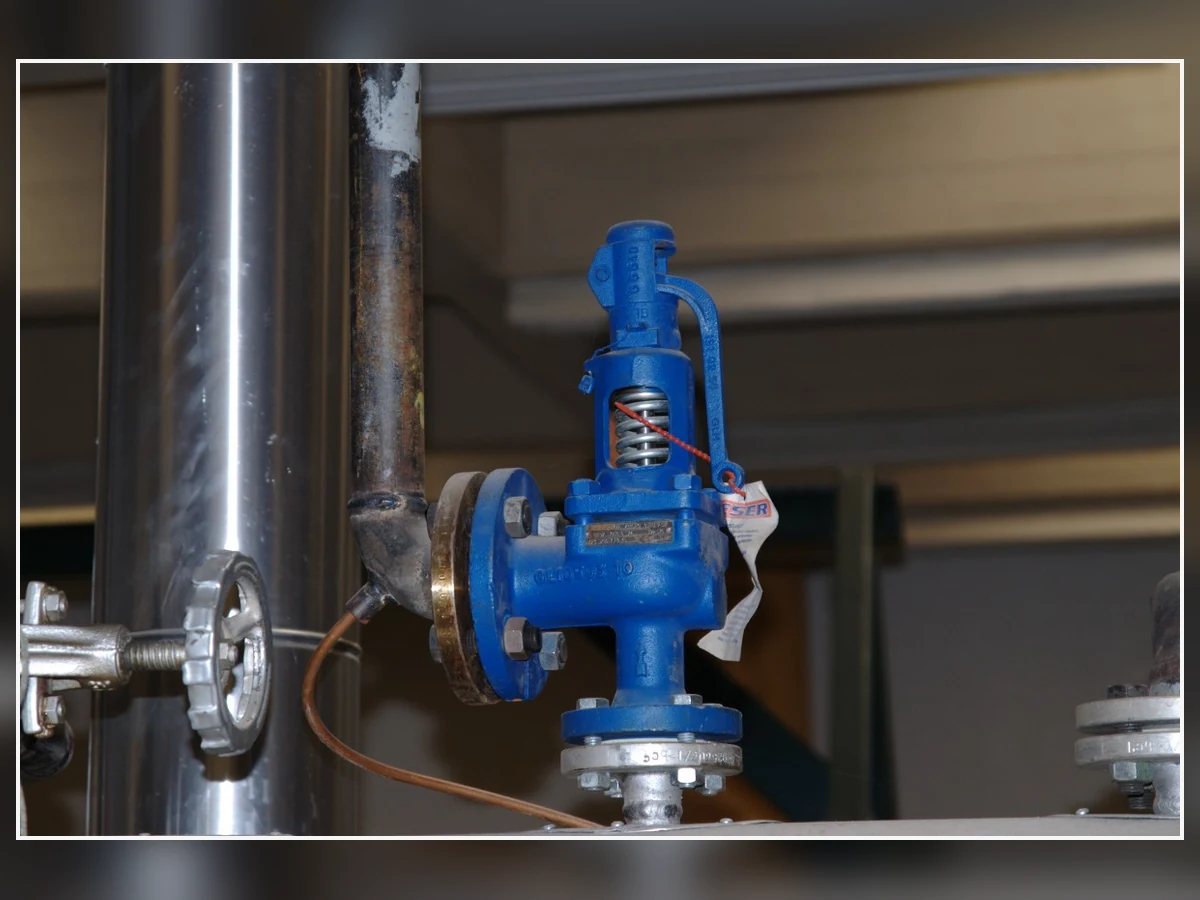
Реальное фото пружинного предохранительного клапана — не клапана с пилотным управлением. Используется только для демонстрации того, что внешний вид не может определить действие Pop или модулирующее пилотное управление.
Автор изображения: K. Krallis / SV1XV — CC BY-SA 3.0.
Открытие с хлопком и модулирующее открытие: инженерное сравнение вкратце
| Фактор выбора | Пилот с хлопающим действием | Пилот с модулирующим действием | Требуется проверка |
|---|---|---|---|
| Основное поведение открытия клапана | Быстрый переход к расчетному открытию после срабатывания пилота | Плавный подъем при контроле давления в камере | Кривая подъёма от давления производителя |
| Связь с избыточным давлением | Спроектирован для чёткого открытия | Подъём реагирует на избыточное давление в пределах выбранной конструкции | Избыточное давление, необходимое для паспортной пропускной способности |
| Профиль потребности в сбросе давления | Часто подходит для быстро растущего или длительного спроса | Часто подходит для переменного спроса | Определяющий профиль потока при сбросе давления |
| Сбрасываемый продукт | Может пропускать больше потока, чем требуется при небольшом возмущении | Может ограничивать сброс во время небольшого события | Фактический профиль события и выходная система |
| Чувствительность к цикличности | Может циклировать, если клапан завышен по размеру или устойчивый поток слишком мал | Может циклировать, если динамика системы, чувствительность или выбор клапана не подходят | Анализ динамики и установленной системы |
| Чувствительность к потере давления на входе | По-прежнему зависит от давления на клапане и в точке отбора импульса пилота | По-прежнему зависит; дистанционный отбор импульса может изменить точку контроля | Оценка потерь на входе и схема отбора импульса |
| Сброс пилотного газа | Может сбрасывать в атмосферу или в другое место в зависимости от конструкции | Может сбрасывать в атмосферу или в выходной патрубок основного клапана в зависимости от конструкции | Компоновка производителя и анализ опасности выброса |
| Противодавление | Не решается с помощью маркировки действия | Не решается с помощью маркировки действия | Данные по наложенному и накопленному противодавлению |
| Среда и фаза | Зависит от модели | Зависит от модели | Аттестованная или документально подтвержденная среда |
| Среда с загрязнениями или конденсатом | Малые проходные сечения, седла и трубки остаются уязвимыми | Малые проходные сечения, седла и трубки остаются уязвимыми | Проверка загрязнения, фильтрации, дренажа и обогрева |
| Сброс давления и повторное закрытие | Конструктивные особенности | Конструктивные особенности | Заводские настройки и данные о производительности |
| Подтверждение производительности | Требуется для полной конфигурации клапана | Требуется для полной конфигурации клапана | Выбранное проходное сечение, среда, давление и температура |
| Техническое обслуживание | Пилот, купол и цепь датчика требуют проверки | Пилот, модулятор, купол и цепь датчика требуют проверки | Руководство по техническому обслуживанию, запасные части и процедура испытаний |
Таблица является инструментом предварительного отбора, а не окончательным выбором. Одна и та же маркировка открытия может быть реализована по-разному в разных сериях изделий. Данные выбранного производителя должны подтверждать точный механизм, рабочий диапазон, реакцию на давление и сертификационную основу.
Предварительная матрица выбора
Используйте эту матрицу только для предварительного отбора. Она не заменяет расчет сброса давления, выбор производителя, проверку установленной системы или принятые нормы и проектную спецификацию.
| Техническое условие | Действие с хлопком является более сильной отправной точкой, когда… | Модулирующее действие является более сильной отправной точкой, когда… | Остановитесь и подтвердите перед выбором |
|---|---|---|---|
| Профиль потребности в сбросе давления | Управляющий спрос быстро растет, и ожидается, что он останется достаточно высоким, чтобы обеспечить решительную реакцию открытия. | Ожидается, что спрос будет изменяться или снижаться, и подъем, реагирующий на давление, может уменьшить ненужный сброс. | Профиль нагрузки сброса, определяющий расчетный случай и требуемая пропускная способность не установлены. |
| Требуемая производительность | Точная конфигурация обеспечивает документированную пропускную способность, требуемую для расчетного случая, при допустимом избыточном давлении. | Точная конфигурация обеспечивает требуемую пропускную способность, допуская контролируемый подъем при менее значительных событиях. | Известны только размер присоединения, давление настройки или визуальный размер клапана. |
| Рабочий запас и цикличность | Данные производителя и установленная система обеспечивают стабильное открытие и посадку при ожидаемой истории давления. | Кривые производителя обеспечивают плавный подъем без неустойчивой цикличности при ожидаемой истории давления. | Клапан завышен по размеру, процесс пульсирующий или устойчивый сброс расхода неопределен. |
| Рабочая среда и загрязнения | Выбранный пилот задокументирован для фактической среды, температуры и мер контроля загрязнений. | Выбранный модулирующий пилот задокументирован для фактической среды, а риск загрязнения малых проходных каналов контролируется. | Грязная, конденсирующаяся, замерзающая, полимеризующаяся или двухфазная среда не рассматривалась. |
| Потери на входе и в линии восприятия давления | Пилот воспринимает репрезентативное давление, а потери на входе остаются приемлемыми для выбранной схемы. | Схема восприятия давления может обеспечить требуемое регулирование по давлению без задержки или засорения. | Отсутствуют данные по дистанционному восприятию давления, изоляции, диаметру импульсной трубки, дренажу или потерям на входе. |
| Противодавление и выхлоп пилота | Схема выхлопа основного клапана и пилота задокументирована для наложенного и создаваемого противодавления. | Основной клапан и модулирующий пилот остаются стабильными в ожидаемом диапазоне давления на выходе. | Не определены место выхлопа пилота или переменное давление в коллекторе. |
| Эксплуатационная цель | Решающее срабатывание важнее, чем ограничение сброса при незначительном событии. | Соответствие спросу и сокращение необязательного сброса имеют определенную технологическую ценность. | Эксплуатационная цель не была связана с определяющим случаем сброса. |
Начните с governing-сценария сброса, а не с названия пилота
Действие пилота должно соответствовать определяющему случаю сброса, а не заводской табличке оборудования. Определите защищаемое оборудование, реальный сценарий, требуемую нагрузку, базовое давление и то, как спрос изменяется во время события.
Для более широкого анализа сценариев сброса, используйте руководство ZOBAI по системам сброса давления API 521 перед сравнением действий пилота.
Внезапный и продолжительный спрос на сброс
Заблокированный выход, отказ регулятора или подобное событие могут создать быстро растущую нагрузку, которая остается высокой. Решительный отклик с резким открытием может быть полезен, но только после проверки пропускной способности и устойчивости установленной системы.
Переменный или самоограничивающийся спрос на сброс
Некоторые события нарастают, а затем снижаются по мере изменения запаса, подвода тепла или расхода вышестоящего потока. Модулирующее действие может уменьшить необязательный сброс, но определяющая максимальная нагрузка по-прежнему контролирует расчет.
Несколько случаев сброса должны проверяться отдельно
Различные сценарии могут определять пропускную способность, температуру, фазу, противодавление или выбор материала. Не объединяйте их в один предполагаемый расчетный случай без принятого анализа сброса.
Требуемая пропускная способность и подъем основного клапана связаны, но не взаимозаменяемы
Характер открытия и пропускная способность связаны, но не взаимозаменяемы. Определяющий сценарий сброса устанавливает требуемую нагрузку; выбранная конфигурация основной клапан/пилот должна иметь документально подтвержденную пропускную способность для соответствующей среды, давления сброса и температуры.
Используйте ZOBAI руководство по расчету и сертифицированной пропускной способности предохранительных клапанов для разделения требуемой нагрузки, требуемой площади, выбранного проходного сечения и документально подтвержденной пропускной способности.
Требуемая нагрузка определяется сценарием сброса
Требуемая пропускная способность определяется защищаемым оборудованием и определяющим достоверным сценарием, а не давлением настройки, размером присоединения, визуальным размером клапана, маркировкой пилота или тем фактом, что предыдущий клапан занимал то же место.
Сертифицированная или документально подтвержденная пропускная способность определяется выбранной конфигурацией клапана
Доказательства пропускной способности должны соответствовать выбранной модели, проходному сечению, конфигурации, среде и условиям сброса. Два клапана с одинаковым размером фланца могут иметь разные эффективные площади прохода и документально подтвержденную пропускную способность.
Частичный подъем не снижает определяющее требование
Модулирующий клапан может работать с частичным подъемом при менее значительном событии, но максимальный достоверный случай по-прежнему определяет требуемую пропускную способность. Базы пропускной способности для пара, газа/пара, жидкости, вскипающей и двухфазной среды не могут заменять друг друга без принятого инженерного обоснования.
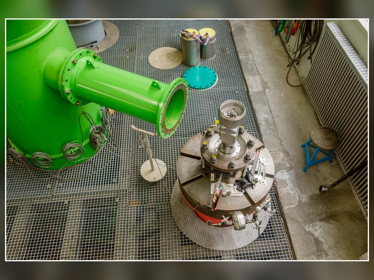
Фотография реальной испытательной лаборатории предохранительно-сбросных клапанов. Она иллюстрирует необходимость доказательств испытаний и пропускной способности, но не является сертификатом ZOBAI, результатом пропускной способности или заявлением о продукте.
Автор изображения: CEphoto, Uwe Aranas — CC BY-SA 4.0.
Что доказывает и что не доказывает каждое доказательство
| Доказательство | Что это может установить | Что он не может установить самостоятельно | Требуемое последующее действие |
|---|---|---|---|
| Испытание на давление срабатывания | Клапан начинает открываться при испытанном давлении в указанных условиях испытания. | Требуемая пропускная способность при сбросе, сертифицированная пропускная способность, устойчивость установки или достаточность выходной системы. | Подтверждение пропускной способности, проверка сброса давления/повторной посадки и анализ установленной системы. |
| Размер и класс присоединения | Физическое присоединение и параметры давление-температура при подтвержденных материале и стандарте. | Эффективное проходное сечение, коэффициент, пропускная способность при полной конфигурации или пригодность пилотного действия. | Габаритный чертеж, обозначение проходного сечения, паспорт производителя и документ о пропускной способности. |
| Наблюдение за подъемом основного клапана | Клапан переместился во время наблюдаемого события или испытания. | Пропущенный поток, защищаемый расчетный случай или достигнутая сертифицированная пропускная способность. | Кривая подъема от давления, расчетная база и документация по пропускной способности. |
| Требуемый расчет сбрасываемой нагрузки | Технологическая нагрузка, которая должна быть сброшена для расчетного сценария. | Что конкретный клапан или проходное сечение может пропустить эту нагрузку. | Сравнение пропускной способности для конкретной модели и конфигурации. |
| Документ производителя о пропускной способности | Документированная пропускная способность для указанной модели, проходного сечения, среды, давления и конфигурации. | Что монтажный трубопровод, линии восприятия давления, противодавление и состояние обслуживания приемлемы. | Проверка установленной системы, материалов и проектных норм. |
| Заводская табличка или предыдущая модель | Идентификация и выбранные данные для установленного клапана, где они читаемы и полны. | Что прежний выбор остается подходящим после изменений технологического процесса, производительности или трубопроводной обвязки. | Проверка управления изменениями и замены. |
Правило контроля производительности
Размер присоединения не является пропускной способностью сброса.
Давление настройки не является требуемой или сертифицированной пропускной способностью.
Базы пропускной способности для пара, газа, жидкости и двухфазной среды не взаимозаменяемы.
Меньшее наблюдаемое событие не снижает требуемую пропускную способность для определяющего достоверного сценария.
Рабочий запас, избыточное давление, обратный сброс и цикличность
Рабочее давление, давление настройки, избыточное давление, аккумуляция и давление повторной посадки описывают разные части цикла сброса. Выбранное действие должно оставаться стабильным в течение фактической истории давления; ни модуляция, ни быстрое открытие не исправляют завышенный клапан или неподходящий трубопровод.
Работа вблизи давления настройки требует проверенных характеристик
Когда нормальное давление приближается к давлению настройки, проверьте герметичность седла, стабильность пилота и рекомендуемый производителем запас по рабочему давлению для конкретной конструкции.
Модуляция не устраняет автоматически циклирование
Модулирующий клапан все еще может циклировать, когда устойчивый расход низкий, процесс пульсирует, задержка датчика или выходная система взаимодействует с клапаном.
Хлопкообразное срабатывание не гарантирует автоматически стабильный полный подъем
Быстрое открытие может по-прежнему вызывать дребезжание или повторную посадку, если потери на входе, противодавление, расчет или профиль требуемого сброса неподходят.
Анализ динамического поведения
| Наблюдаемое или ожидаемое поведение | Возможные причины | Доказательства для запроса | Опасный путь для избежания |
|---|---|---|---|
| Повторное открытие и посадка | Завышенный клапан, низкий устойчивый расход, узкий рабочий диапазон, пульсация процесса, неподходящий продувочный дифференциал или взаимодействие на выходе. | История давления, требуемый профиль расхода, кривые подъема/продувки, записи фактического состояния и данные трубопроводов. | Изменение действия пилота без проверки расчета и динамики системы. |
| Пульсация или вибрация | Потери давления на входе, чрезмерное противодавление, акустическое взаимодействие, механическая нагрузка, задержка срабатывания датчика или недостаточный расход. | Расчеты входа/выхода, данные о вибрации, анализ опор и рекомендации производителя по динамике. | Рассмотрение дребезжания только как проблемы настройки давления срабатывания. |
| Утечка вблизи рабочего давления | Недостаточный эксплуатационный запас, повреждение седла, загрязнение, термическая деформация или нестабильное пилотное управление. | Данные эксплуатации, результаты проверки герметичности седла, осмотр пилота и данные по выбранному седлу. | Предполагая, что только модулирующее действие улучшит герметичность. |
| Задержка открытия | Забитая импульсная линия, замерзший конденсат, ограниченный выхлоп пилота, неправильная изоляция или загрязненное седло пилота. | Проверка трубопровода, контроль дренажа, функциональное испытание и схема пилота. | Повышение давления настройки для маскировки замедленной реакции. |
Среда, фаза и загрязнение могут иметь приоритет над предпочтительным типом открытия
Универсальное правило, например “щелчок для газа и модуляция для жидкости”, небезопасно. Продуктовые линейки производителей различаются, и некоторые поддерживают оба действия для нескольких сред. Окончательная пригодность зависит от точной комбинации пилотного и основного клапана, основы расчёта по среде, температуры сброса, риска загрязнения и материалов.
Для сжимаемых и несжимаемых сред требуется правильная основа расчёта пропускной способности
Для газа, пара, пара и жидкости используются разные основы расчёта пропускной способности. Вскипание и двухфазная среда требуют дополнительного анализа, и поведение подъёма не заменяет этот анализ.
Малые проходные сечения пилота создают риски загрязнения и замерзания
Седла пилота, фильтры, трубки и малые проходные сечения могут быть засорены твёрдыми частицами, воском, полимером, конденсатом, льдом или гидратами. Любая фильтрация, чистый источник давления, дренаж, изоляция или теплоспутник должны быть одобрены для выбранной конструкции и обслуживаться как часть функции защиты.
Выбор материалов выходит за пределы корпуса основного клапана
Проверьте корпус, сопло, диск, поршень, направляющую, шпиндель, пилотную арматуру, трубки, пружины, уплотнения, прокладки и фильтры. Только марка корпуса не определяет коррозионную стойкость, температурный режим или допустимость отложений для всей пилотной цепи.
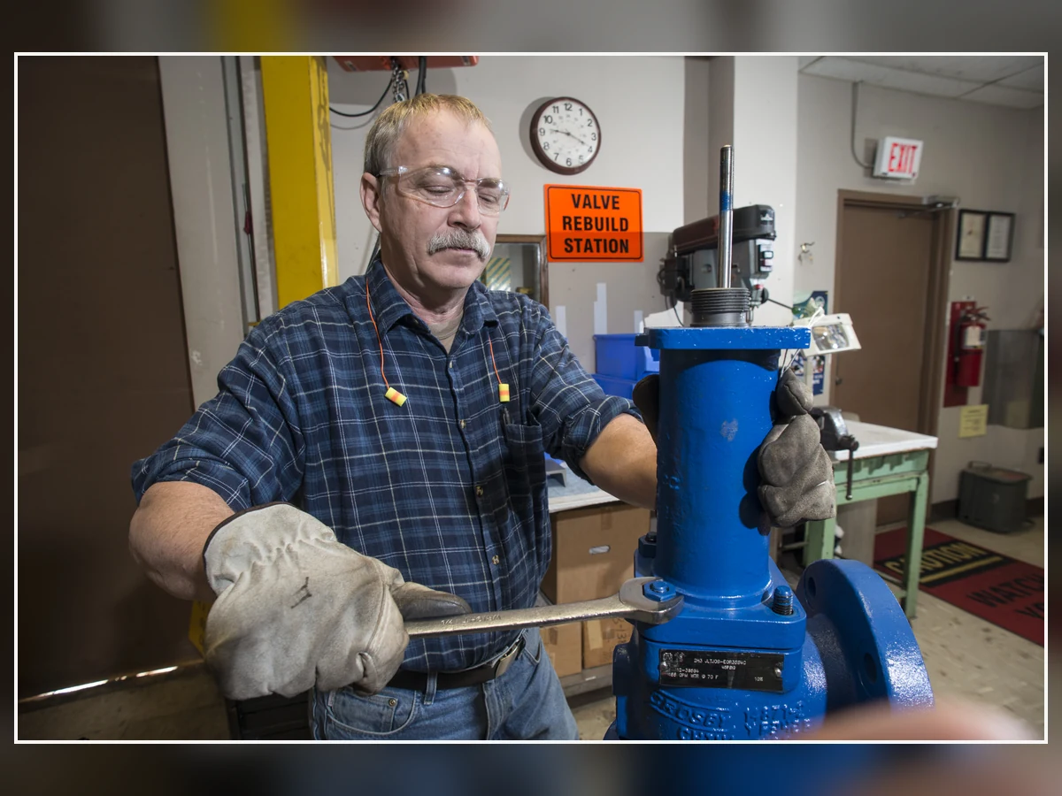
Реальное фото ремонта предохранительного клапана. Оно иллюстрирует вопросы технического обслуживания и загрязнения и не относится к проектам заказчиков ZOBAI.
Автор изображения: Сайт Саванна-Ривер / Министерство энергетики США — Общественное достояние (работа федерального правительства США); в Commons также указан источник CC BY 2.0.
Среда, пилотная цепь и контроль материалов
| Условие | Основной инженерный риск | Детали, требующие проверки | Данные или управление, необходимые |
|---|---|---|---|
| Чистый газ или пар | Высокая скорость потока, утечка в седле, быстрое повышение давления и возможное циклирование. | Пилотное седло, основное седло, уплотнения, трубки, выпускной канал и арматура. | Свойства среды, профиль сброса, рабочий запас и задокументированная основа для газа/пара. |
| Пар или конденсирующийся пар | Конденсация, температурные эффекты, накопление воды и возможная закупорка пилотной линии. | Пилотные каналы, трубопроводы, дренажи, уплотнения, корпус/внутренние детали и любые компоненты с обогревом. | Температура сброса, план дренажа, объем поставки пара производителем и меры контроля обслуживания. |
| Жидкостная среда | Гидравлическая нестабильность, скачки давления, эффекты жидкостных пробок и различная расчетная база. | Внутренние детали главного клапана, конфигурация пилота, уплотнения, линия отбора давления и дренаж на выходе. | Свойства жидкости, вязкость, риск вскипания и задокументированные характеристики по жидкости. |
| Вскипание или двухфазный поток | Неверная расчетная база и непредсказуемое изменение фазы через клапан и выходной трубопровод. | Полный клапан, входной трубопровод, выходная система и схема отбора давления пилота. | Специализированный анализ сброса и подтверждение производителя для фактического фазового поведения. |
| Загрязненная, воскообразная или полимеризующаяся среда | Закупорка малых пилотных каналов, фильтров, седел и трубопроводов. | Пилот, фильтр, линия отбора давления, линия загрузки, уплотнения и точки промывки. | Описание загрязнения, интервал технического обслуживания, допустимый источник чистого продукта или альтернативная конфигурация. |
| Коррозионностойкие или кислые среды | Коррозия, коррозионное растрескивание под напряжением, задиры, воздействие на уплотнения и деградация пружины. | Корпус, крышка, сопло, тарелка, направляющая, шпиндель, пружина, трубки, трим пилота, уплотнения и прокладки. | Состав, температура, спецификация материала и требования проекта по коррозии. |
| Заморозка или криогенное воздействие | Лед, гидраты или замерзший конденсат, блокирующие пилотную цепь и изменяющие поведение материала. | Пилот, трубки чувствительности/сброса, уплотнения, корпус/трим и система поддержки. | Минимальная температура, анализ теплопритоков/обледенения, дренаж или обогрев, где допустимо, и данные по конкретной модели. |
Потери на входе, место отбора импульса и сброс пилота должны рассматриваться совместно
Пилот реагирует на давление в фактической точке чувствительности. Давление защищаемого оборудования, давление на входе главного клапана и дистанционное давление могут отличаться во время сброса, поэтому потери на входе, схема чувствительности и выхлоп пилота должны рассматриваться как единая система управления.
ZOBAI руководство по установке предохранительного клапана обеспечивает более широкие проверки входа, выхода, опоры, дренажа и сбросного трубопровода.
Пилот может реагировать только на давление, которое он фактически ощущает
Встроенная чувствительность обычно привязана к давлению вблизи входа клапана. Если давление на входе падает во время сброса, пилот и главный клапан могут не видеть одинаковое давление с защищаемым оборудованием.
Дистанционное зондирование может помочь, но создает собственные пути отказов
Дистанционное зондирование позволяет приблизить точку контроля к защищаемому оборудованию, но добавляет такие виды отказов, как засорение трубки, ее длина, дренаж, блокировка, вибрация и обслуживание.
Трассировка выхлопа пилота является частью спецификации клапана
Сброс пилота может осуществляться в атмосферу, быть подключен к выходу главного клапана или организован иным способом, одобренным производителем. Место сброса влияет на опасный выброс, давление сброса, конденсацию, замерзание и воздействие противодавления. Проточный/непроточный тип — это отдельная конструктивная переменная, отличная от характера действия (открытие с хлопком или модулирующее).
Памятка по монтажу и пилотной схеме: что можно и что нельзя
| Делать | Почему это важно | Не следует | Возможный риск |
|---|---|---|---|
| Убедитесь, что пилот действительно воспринимает давление в контрольной точке. | Пилот реагирует на это давление, а не автоматически на давление в защищаемом оборудовании. | Предполагается, что давление на входе клапана и в защищаемом оборудовании всегда одинаково. | Задержка открытия, преждевременная посадка или неправильная точка контроля. |
| Рассчитайте потери на входе для расчетного расхода и установленной геометрии. | Потери на входе влияют на давление на клапане и могут способствовать нестабильности. | Полагаться на номинальный размер трубы или краткий визуальный осмотр. | Невыявленное ограничение или чрезмерные потери. |
| Прокладывайте трубку дистанционного отбора давления, избегая засорения, жидкостных пробок и механических повреждений. | Состояние трубки определяет, насколько быстро и точно пилот воспринимает давление. | Не добавляйте длинную, извилистую или изолированную трубку отбора давления без проверки. | Задержка или отключение реакции пилота. |
| Подтвердите место сброса и давление выхлопа пилота. | Маршрут выхлопа может влиять на опасный выброс, поведение пилота и воздействие противодавления. | Не вентилируйте в закрытое или находящееся под давлением место без одобрения производителя/проекта. | Небезопасный выброс или изменение открытия/посадки. |
| Независимо поддерживайте тяжелый выходной трубопровод и учитывайте реакционные нагрузки. | Механическая нагрузка может деформировать клапан и повредить трубку пилота. | Не используйте корпус клапана в качестве опоры для выхлопного трубопровода. | Несоосность, утечка, вибрация или структурные повреждения. |
| Обеспечьте дренаж и проверьте нижние точки. | Скопление жидкости может изменить сопротивление на выходе и поведение пилота/сброса. | Допускайте закрытый или недренируемый карман на выходе. | Создаваемое противодавление, коррозия или гидравлическая нагрузка. |
Противодавление по-прежнему требует проверки с учетом данных производителя
Работа пилота не делает давление на выходе несущественным. Разделите внешнее противодавление, создаваемое противодавление, давление на выходе главного клапана и давление сброса пилота, затем сравните их с задокументированными пределами и базой пропускной способности/стабильности выбранного производителя.
Откройте инженерное руководство ZOBAI по противодавлению и сильфону для полного анализа внешнего, создаваемого и выходного коллектора.
Балансировка главного клапана и сброс пилота — отдельные проверки
Главный клапан может быть уравновешен по давлению, в то время как сброс пилота все еще испытывает давление на выходе или в коллекторе. Оба пути должны быть проверены на открытие, продувку, повторную посадку и эффекты обратного потока.
Переменное давление в коллекторе может изменить цикл сброса
Общий коллектор может изменять давление по мере открытия других устройств. Поэтому гидравлика на выходе, реакционные нагрузки, опоры, дренаж и скопление жидкости остаются частью окончательного выбора.
Ключевые точки принятия решения по противодавлению
| Входное противодавление | Вопрос, на который нужно ответить | Почему это меняет выбор | Требуется подтверждение |
|---|---|---|---|
| Наложенное противодавление | Какое давление существует на выходе до открытия клапана, и является ли оно постоянным или переменным? | Оно может влиять на основной клапан, выхлоп пилота и поведение открытия/закрытия. | Нормальный и аварийный диапазон выходного давления, а также пределы выбранной модели. |
| Накопленное противодавление | Какое давление возникает при прохождении требуемого расхода через систему сброса? | Оно может снизить пропускную способность, изменить стабильность и изменить цикл сброса. | Гидравлический расчет выхода и данные производителя по коррекции/характеристикам. |
| Давление выхлопа пилота | Выхлоп пилота идет в атмосферу, в основной выход или в другое контролируемое место? | Пилот может видеть давление, отличное от давления на выходе основного клапана. | Схема пилотного управления и допустимый диапазон давления на выхлопе. |
| Общий коллектор переменного давления | Могут ли другие сбросные устройства или технологические события изменить давление на выходе во время сброса? | Переменная головка может изменять характеристики подъема, сброса давления и цикличности срабатывания. | Сценарии для коллектора, одновременная нагрузка и анализ переходных режимов при необходимости. |
| Дренаж и скопление жидкости | Может ли конденсат или дождевая вода скапливаться в выходной системе? | Гидростатический напор жидкости и гидроудары могут создавать дополнительное сопротивление и механическую нагрузку. | Проверка места дренажа, уклона, нижней точки и опор. |
Когда ударное действие обычно является лучшей отправной точкой
Пружинный (поп-действие) предохранительный клапан обычно является более предпочтительным исходным вариантом, когда определяющее событие требует быстрого перехода к большому открытию, а сбросная нагрузка, как ожидается, останется высокой.
Сильные признаки соответствия
Сильными признаками являются быстрорастущий устойчивый спрос, четкая необходимость в решительном реагировании и подтверждение производителем того, что конкретный клапан достигает требуемой пропускной способности и остается стабильным.
Условия, требующие осторожности
Проверьте повторно низкий устойчивый расход, завышенное проходное сечение, пульсацию, загрязнение, задержку срабатывания датчика, переменное противодавление и неполные данные по обратному давлению (blowdown).
Не принимайте окончательное решение в пользу клапана с резким открытием (pop-action), если…
Потребность в сбросе мала или неопределенна относительно выбранного проходного сечения, и устойчивый расход не был подтвержден.
Каналы пилота подвержены загрязнению или замерзанию без утвержденной стратегии управления.
Производитель не предоставил данные по подъему, пропускной способности, обратному давлению (blowdown) и условиям эксплуатации для точной конфигурации.
Когда модулирующее действие обычно является лучшей отправной точкой
Модулирующее действие обычно является более предпочтительным исходным вариантом, когда потребность в сбросе изменяется во время события, а подъем, зависящий от давления, обеспечивает определенное преимущество для технологического процесса или контроля сброса.
Сильные признаки соответствия
Сильными индикаторами являются переменная потребность, необходимость ограничения нежелательного сброса и кривые производителя, показывающие стабильный прогрессивный подъем при сохранении полной регулирующей пропускной способности.
Условия, требующие осторожности
Проверьте повторно загрязнение, задержку срабатывания датчика, нестабильное давление процесса, требуемый полный подъем, обратное давление (blowdown), противодавление и то, не используется ли модуляция для маскировки завышенного размера клапана.
Не принимайте окончательное решение в пользу модулирующего действия, когда…
Оно используется как замена правильному расчету размера, допустимым потерям на входе или стабильной системе сброса.
Потребность процесса недостаточно изучена, чтобы обосновать подъем, зависящий от давления.
Полная требуемая пропускная способность, характер циклирования, устойчивость к загрязнению и повторная посадка не задокументированы.
Типичные ошибки выбора и их цепочки отказов
Ошибки при выборе обычно образуют цепочку: неполные исходные данные по сбросу или установке приводят к неподдерживаемой конфигурации, которая затем проявляется в виде цикличности, задержки открытия, недостаточного регулирования давления, утечки или медленной посадки. Используйте следующую матрицу для определения следующей инженерной проверки; не рассматривайте её как разрешение на несогласованную регулировку на месте.
Наблюдаемое поведение, вероятные причины и проверки
| Наблюдаемое поведение | Возможные причины | Немедленные инженерные проверки | Граница эскалации |
|---|---|---|---|
| Клапан открывается и закрывается повторно | Завышенный размер, низкий устойчивый расход, пульсация процесса, потери на входе, взаимодействие с давлением на выходе или неподходящий продувочный дифференциал. | Проверьте требуемую нагрузку, выбранное проходное сечение, историю давления, расчеты входа/выхода и кривые производителя. | Не продолжайте повторную цикличность без инженерного анализа; механические повреждения и утечки могут усилиться. |
| Клапан с пилотным управлением не открывается при ожидаемых условиях системы | Закупорка линии отбора, неправильная изоляция, замерзший конденсат, ограниченный выхлоп, ошибка в установленном давлении или повреждение пилота. | Подтвердите безопасное состояние системы, проверьте трассу отбора/выхлопа и просмотрите записи испытаний. | Выведите из защитной службы или создайте утвержденный альтернативный путь защиты, если это требуется владельцем или нормами. |
| Клапан открывается, но давление остаётся неуправляемым | Недостаточная пропускная способность, неверная расчётная среда, чрезмерные потери на входе, высокое накопленное противодавление или ограниченный сброс. | Сравните требуемую нагрузку с документированной пропускной способностью и проверьте установленный трубопровод. | Не предполагайте, что большее присоединение или больший подъём решат определяющий случай. |
| Утечка после срабатывания | Повреждение седла, загрязнение, перекос, термическая деформация, нестабильное циклирование или посторонние частицы. | Проверьте состояние седла/пилота, проанализируйте историю давления при срабатывании и выполните предписанные испытания. | Полевая регулировка без утверждённой процедуры может изменить давление настройки и прослеживаемость. |
| Медленная или нестабильная посадка | Ограничение наполнения пилота, давление на выходе, загрязнение, неверная настройка обратного давления или восстановление технологического давления. | Проверьте контур пилота, давление на выходе и методику производителя по обратному давлению. | Не применяйте универсальное значение обратного давления для разных производителей или условий эксплуатации. |
Комплексные инженерные сценарии для обучения выбору
Как использовать сценарии
Это комплексные инженерные сценарии для обучения, а не проекты клиентов ZOBAI и не заявления о характеристиках.
Каждое предварительное предпочтение остается условным до завершения проверки пропускной способности, давления, среды, чувствительности, противодавления, материалов и подтверждающих документов производителя.
Сценарий 1 — Быстрое возмущение газовой системы с длительным высоким сбросом
Возмущение газовой системы создает быстрорастущую нагрузку, которая остается высокой. Предварительное направление — отрывное действие, при условии требуемой пропускной способности, потерь на входе, противодавления, места отбора импульса и точных данных производителя.
Протокол решения по сценарию
Предварительное направление: отрывное действие может быть более предпочтительным, поскольку определяющая нагрузка быстро растет и остается значительной.
По-прежнему необходимы: определяющая нагрузка, документально подтвержденная пропускная способность, базис по превышению давления, потери на входе, давление на выходе, место отбора импульса, выхлоп пилота и точная конфигурация производителя.
Сценарий 2 — Переменное технологическое возмущение, при котором сброс снижается во время события
Нагрузка растет, а затем снижается по мере изменения технологических условий. Предварительное направление — модулирующее действие, при условии, что клапан по-прежнему защищает от максимально возможного случая и не циклирует.
Протокол решения по сценарию
Предварительное направление: модулирующее действие может быть более предпочтительным, поскольку потребность в сбросе меняется во время события.
По-прежнему необходимы: полная пропускная способность для определяющего случая, минимальный стабильный отклик, поведение при циклировании/продувке, восстановление технологического давления и анализ системы сброса.
Сценарий 3 — Загрязненная или конденсирующаяся среда с длинной импульсной трубкой
Загрязненная или конденсирующаяся среда и длинная импульсная трубка создают риски засорения и задержки отклика. Ни одно из действий не должно выбираться, пока не будут приняты меры по защите пилотной цепи, дренажу, фильтрации и техническому обслуживанию.
Протокол решения по сценарию
Предварительное направление: ни одно из действий не должно выбираться, пока пилотная цепь не будет защищена от засорения, конденсации и задержки отклика.
Дополнительно требуется: описание загрязнения, схема трубопроводов, дренаж, возможность подачи чистого воздуха или чистого газа, доступ для обслуживания и ограничения производителя.
Данные, необходимые для запроса предложения перед выбором ударного или модулирующего действия
Перед запросом цены подтвердите наличие достаточной информации для выбора полного клапана, а не только пилота.
Данные по процессу и сбросу давления
| Обязательное поле | Почему это меняет решение |
|---|---|
| Защищаемое оборудование | Определяет применимый код оборудования и цель защиты |
| Управляющий сценарий сброса давления | Определяет профиль нагрузки и требуемую производительность |
| Среда и фаза | Определяет основу расчета, пригодность пилота и материалы |
| Состав и загрязнение рабочей среды | Выявляет риски коррозии, засорения, полимеризации, замерзания или повреждения уплотнений |
| Рабочее давление | Устанавливает нормальный запас до условия открытия |
| МАОР/расчетное давление | Устанавливает предел оборудования в соответствии с принятой расчетной базой |
| Давление настройки | Определяет цель настройки клапана; не подтверждает пропускную способность |
| Допустимое превышение давления/аккумуляция | Определяет доступное давление для пропускной способности клапана и управления системой |
| Требуемая пропускная способность | Устанавливает расход, который должен быть пропущен |
| Методика расчета пропускной способности | Позволяет производителю проверить допущения |
| Температура сброса | Изменяет свойства среды, материалы, уплотнения и пропускную способность |
Данные установленной системы
| Обязательное поле | Почему это меняет решение |
|---|---|
| Входное соединение и трубопровод | Влияет на посадку, потери на входе и устойчивость |
| Выходное соединение и трубопровод | Влияет на противодавление, реакцию и дренаж |
| Расчетное наложенное противодавление | Определяет давление на выходе до открытия |
| Расчетное накопленное противодавление | Определяет давление на выходе при потоке |
| Встроенное или дистанционное измерение | Определяет точку управления пилотом |
| Длина, диаметр и трассировка импульсной линии | Влияет на задержку, засорение и конденсацию |
| Место сброса выхлопа пилота | Влияет на безопасность и работу пилота |
| Условия окружающей среды | Выявляет риски замерзания, нагрева или коррозии |
| Ориентация, опоры и доступ | Влияет на монтаж и обслуживание |
Требования к клапану, материалам и документации
| Обязательное поле | Почему это меняет решение |
|---|---|
| Материалы основного клапана и пилота | Подтверждает совместимость всех открытых деталей |
| Тип седла и уплотнения | Влияет на герметичность, температурный режим и пригодность для рабочей среды |
| Предпочтение: хлопающий или модулирующий тип | Фиксирует предварительный выбор, а не окончательное решение |
| Требование к пилоту: проточный или непроточный | Определяет отдельное решение по архитектуре пилота |
| Применимый код и принятая редакция | Определяет расчет, сертификацию, испытания и маркировку |
| Документация по производительности | Подтверждает, что предлагаемая конфигурация может защитить данный объект |
| Испытания на давление настройки и герметичность седла | Определяет объем испытаний; не заменяет проверку пропускной способности |
| Требования к функциональным испытаниям | Подтверждает работу пилота и основного клапана, где это применимо |
| Материальные документы и прослеживаемость | Поддерживает закупку и проверку качества |
| ГА, технические паспорта и руководства | Поддерживает проверку соответствия, монтажа и обслуживания |
| Потребность в запасных частях | Влияет на поддержку жизненного цикла и срок поставки |
| Существующая табличка/технический паспорт | Необходимо для проверки эквивалентности замены |
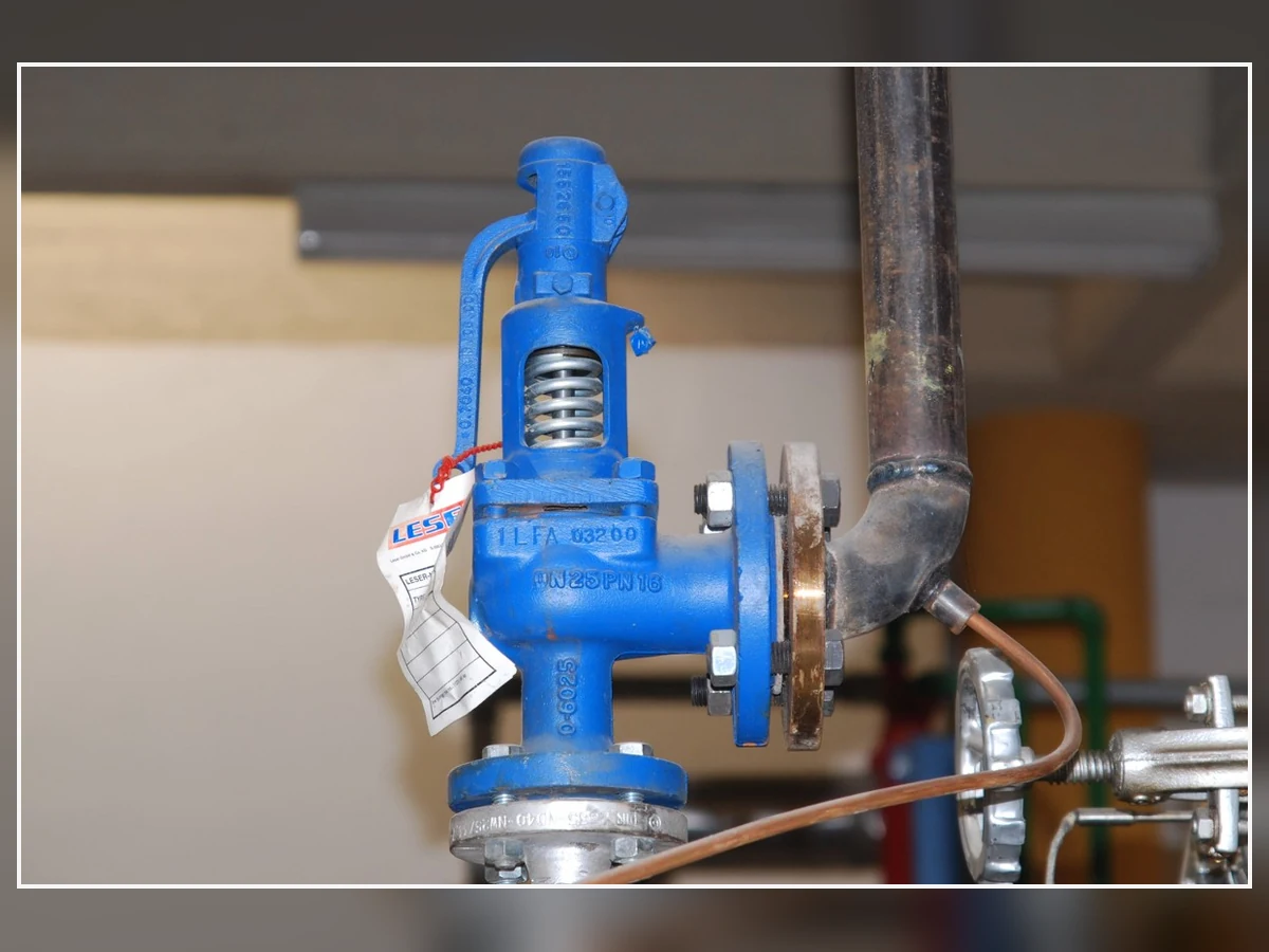
Реальная фотография пружинного предохранительного клапана, а не клапана с пилотным управлением. Используется только для демонстрации того, что замена не может быть одобрена по внешнему виду, размеру фланца или давлению настройки.
Автор изображения: K. Krallis / SV1XV — CC BY-SA 3.0.
Матрица испытаний и документации
| Элемент | Что проверяется | Что должно быть указано в запросе предложения | Что это не заменяет |
|---|---|---|---|
| Проверка давления настройки / функциональное испытание | Давление открытия и функциональная реакция в соответствии с указанной процедурой испытания. | Испытательная среда, критерии приемки, объем свидетельствования, формат отчета и требование к состоянию после испытания. | Расчет пропускной способности, сертифицированная производительность или проверка установленной системы. |
| Испытание герметичности седла | Характеристики герметичности при указанном испытательном давлении и методе. | Применимая процедура/стандарт, тип седла, критерий приемки и отчет. | Проверка давления настройки или подтверждение пропускной способности. |
| Сертификат пропускной способности или документ производителя о пропускной способности | Основание пропускной способности для выбранной модели, проходного сечения, конфигурации и среды. | Точная конфигурация, основание по давлению/температуре, основание по среде и требуемый статус документа. | Подтверждение того, что входной/выходной трубопровод и противодавление приемлемы. |
| Материалы | Указанные материалы и прослеживаемость для заявленных деталей и объема. | Корпус, сопло, диск, направляющая, пружина, пилотная оснастка, трубки, уплотнения и любые проектные записи. | Совместимость со средой, если не рассмотрены полные условия эксплуатации. |
| Габаритный / размерный чертеж | Присоединения, габаритные размеры, ориентация, масса и компоновка вспомогательных элементов. | Точные стандарты входа/выхода, пилотные/измерительные/сбросные соединения и требования к опорам/доступу. | Пропускная способность или адекватность системы сброса давления. |
| Проверка таблички и маркировки | Идентификация и требуемые данные для маркировки поставляемого клапана. | Требуемые коды/проектные маркировки и любые ограничения. | Автоматическое подтверждение того, что каждый проект или юрисдикция принимает клапан. |
| Руководство по установке и техническому обслуживанию | Утвержденные инструкции по установке, эксплуатации, осмотру и обслуживанию. | Инструкция для конкретной модели, перечень запасных частей и требования к обслуживанию пилотной цепи. | Проектирование трубопровода под конкретный проект или определение межремонтного интервала. |
Рабочий процесс проверки замены
| Шаг | Необходимые доказательства | Зачем это необходимо | Не утверждать замену, если… |
|---|---|---|---|
| 1. Идентифицируйте установленный клапан | Заводская табличка, производитель, модель, серийный номер, давление настройки, маркировка проходного сечения/пропускной способности и фотографии. | Определяет, что установлено и являются ли доступные данные полными. | Идентификационные данные или маркировка отсутствуют или противоречивы. |
| 2. Повторно подтвердите основу защиты | Защищаемое оборудование, MAWP/расчетное давление, определяющий сценарий сброса и требуемая пропускная способность. | Проверяет, остается ли первоначальный выбор действительным после изменений технологического процесса. | Технологический процесс или случай сброса изменились без нового расчета. |
| 3. Сравните гидравлическую и механическую совместимость | Стандарт/класс соединения, размеры, масса, ориентация, входной/выходной трубопровод и опоры. | Предотвращает превращение несоответствия размеров в неустойчивую или перегруженную установку. | Совпадает только размер фланца. |
| 4. Сравните совместимость пилота и рабочей среды | Действие с подрывом/плавное, чувствительность, сброс, среда/фаза, температура, загрязнение и материалы. | Подтверждает, что пилотная система может работать в реальных условиях эксплуатации. | Предлагаемый пилот подтверждается только общим заявлением о семействе продуктов. |
| 5. Проверьте пропускную способность и документы | Выбранное проходное сечение, задокументированная пропускная способность, среда, испытания, габаритный чертеж, материалы и документы по принятому кодексу/проекту. | Подтверждает способность защиты и прослеживаемость закупок. | Пропускная способность определяется по размеру присоединения, предыдущей модели или давлению настройки. |
| 6. Контролируйте изменение | Инженерное одобрение, запись об управлении изменениями, проверки установки и план испытаний/инспекций после установки. | Обеспечивает замену в рамках системы защиты от давления, а не просто замену при закупке. | Ни один компетентный инженер-владелец не принял это изменение. |
Финальный алгоритм выбора
Итоговое предварительное резюме решения
| Критерий выбора | Направление поп-действия | Модулирующее направление | Требуемое подтверждение |
|---|---|---|---|
| Профиль потребности в сбросе давления | Быстро растущий и устойчивый управляющий спрос. | Переменный или снижающийся спрос, где реагирующий на давление подъем имеет технологическую ценность. | Утвержденные сценарии сброса и требуемый профиль нагрузки. |
| Производительность | Точная конфигурация достигает требуемой документированной пропускной способности в пределах допустимого избыточного давления. | Точная конфигурация по-прежнему достигает полной управляющей пропускной способности, модулируя меньшие события. | Выбранное проходное сечение, основа для жидкости, давление/температура сброса и данные производителя. |
| Потери на входе и в линии восприятия давления | Репрезентативное срабатывание и приемлемое поведение потерь на входе для решительного открытия. | Репрезентативное измерение без задержки или засорения для стабильного пропорционального регулирования. | Схема встроенного/выносного измерения, трубная обвязка, изоляция, расчет входного участка и схема пилота. |
| Рабочая среда и загрязнения | Выбранный пилот с дискретным открытием, задокументированный для реальной среды и контроля загрязнений. | Выбранный модулирующий пилот, задокументированный для реальной среды и рисков, связанных с малыми проходными сечениями. | Фаза, состав, температура, риск отложений/замерзания, материалы и обслуживание. |
| Противодавление и окончательное подтверждение | Сброс из главного клапана и пилота остается в пределах задокументированных значений. | Пропорциональная работа остается стабильной во всем ожидаемом диапазоне давления на выходе. | Наложенное/накопленное противодавление, место сброса, кривые, испытания, нормы и проектная документация. |
- Определите защищаемое оборудование и основной сценарий сброса. Не начинайте с каталога клапанов.
- Определите требуемую величину сбрасываемого расхода и основу расчета пропускной способности. Подтвердите среду, фазу, давление срабатывания и температуру срабатывания.
- Определите термины давления. Разделите рабочее давление, MAWP/расчетное давление, давление настройки, избыточное давление, аккумуляцию и продувку.
- Охарактеризуйте профиль потребности в сбросе давления. Определите, является ли он резким и продолжительным, переменным, самоограничивающимся или зависит от нескольких случаев.
- Оцените действие сброса и модулирующее действие. Используйте технологический профиль, чтобы определить более сильную отправную точку.
- Проверьте рабочую среду, загрязнения и материалы. Учтите пилот, трубки, уплотнения и основной клапан.
- Проверьте потери на входе, чувствительность и выпуск пилота. Подтвердите давление, которое пилот будет фактически воспринимать.
- Проанализируйте наложенное и нарастающее противодавление. Учтите место выпуска пилота и общий коллектор.
- Сравните данные производительности производителей. Проверьте подъем, пропускную способность, избыточное давление, продувку, рабочий запас и пределы эксплуатации для точной конфигурации.
- Подтвердите испытания, сертификацию и документы. Только стандартное обозначение не завершает спецификацию.
- Выполните полный анализ проекта/кода перед окончательным выбором. Окончательный выбор клапана зависит от реальных условий эксплуатации, принятого кодекса, местных нормативных требований и подтверждения производителя.
Окончательное инженерное подтверждение
Выбранное действие является лишь частью полной спецификации устройства сброса давления.
Окончательный выбор зависит от реальных рабочих данных, определяющего сценария сброса, характеристик производителя для точной конфигурации, принятой редакции кодекса, требований проекта и местного нормативного контроля.
Если какой-либо критический параметр отсутствует, правильным статусом является “подлежит подтверждению”, а не предполагаемая рекомендация по клапану.
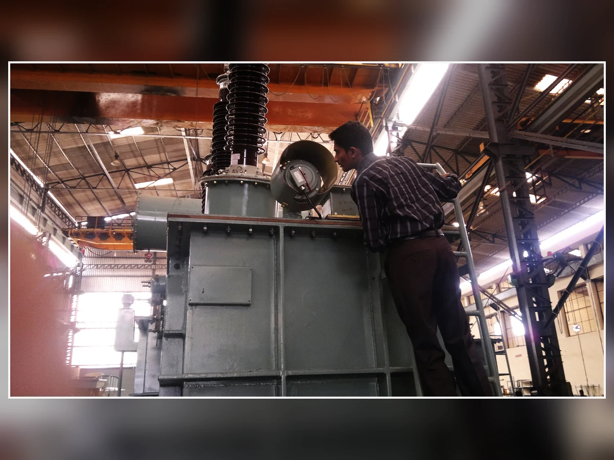
Реальная фотография осмотра клапана сброса давления. Это контекстный актив для окончательной проверки и не должен использоваться в качестве главного изображения технической статьи.
Автор изображения: Shriram — CC BY-SA 3.0.
Часто задаваемые вопросы
В чем основное отличие предохранительных клапанов с пилотным управлением хлопающего и модулирующего действия?
Пружинный пилотный клапан быстрого действия быстро снижает давление в камере, поэтому основной клапан быстро перемещается к расчетному открытию. Модулирующий пилотный клапан управляет давлением в камере постепенно, поэтому подъем основного клапана реагирует на избыточное давление в системе. Точные характеристики зависят от выбранного производителя и модели.
Означает ли хлопающее действие всегда полную сертифицированную пропускную способность при давлении настройки?
№. Подпрыгивающее действие описывает характеристику быстрого открытия. Сертифицированная или задокументированная пропускная способность, необходимое для её достижения избыточное давление и соответствующая среда должны быть подтверждены для конкретной конфигурации клапана.
Пилоты с хлопающим действием предназначены только для газа, а модулирующие пилоты — только для жидкости?
Универсального правила не существует. В некоторых сериях изделий пилоты с хлопающим действием применяются только для газа, тогда как в других сериях предлагаются пилоты с хлопающим или модулирующим действием для пара или жидкости. Используйте данные по условиям эксплуатации и сертификации выбранного производителя.
Может ли предохранительный клапан с модулирующим пилотным управлением снизить потери продукта при каждом сбросе давления?
Не обязательно. Модуляция может ограничивать расход при событиях ниже максимального спроса, но общий сброс также зависит от продолжительности события, реакции процесса, расчета клапана, давления на выходе и определяющей нагрузки сброса.
Какой тип пилотного действия менее подвержен дребезжанию или цикличности?
Ни одно из действий не является автоматически безопасным. Устойчивость зависит от расчета, устойчивого расхода, потери давления на входе, динамики восприятия давления, противодавления, профиля потребности в сбросе и состояния клапана. Требуются данные производителя о характеристиках и анализ установленной системы.
Как потери давления на входе и дистанционное измерение давления влияют на выбор?
Потери на входе могут привести к отличию давления на клапане от давления на защищаемом оборудовании. Дистанционный отбор импульса позволяет перенести точку контроля пилота, однако импульсная линия создает риски засорения, задержки, конденсации, отсечения и повреждения, которые необходимо учитывать при проектировании.
Какие данные необходимо предоставить производителю для выбора пилотного действия?
Укажите защищаемое оборудование, расчетный сценарий сброса, рабочую среду и фазу, рабочее давление, МАРД/расчетное давление, давление настройки, допустимое превышение давления, требуемую пропускную способность, температуру сброса, противодавление, входной/выходной трубопровод, место отбора импульса, выхлоп пилота, материалы, требования норм и документации.
Официальные технические ссылки и ограничения по выбору
Следующие основные источники поддерживают общее сравнение и определяют контекст стандартов. Примеры производителей приведены только для демонстрации того, что продуктовые линейки по-разному реализуют мгновенное и модулирующее действие; их диапазоны давления, температуры, сред, избыточного давления, продувки, пропускной способности и разрешений не должны переноситься на другого производителя или модель.
Основные источники, использованные для технического обзора
| Основной источник | Что поддерживается | Граница |
|---|---|---|
| Emerson Birkett Safeset | Текущая страница семейства продуктов подтверждает, что Safeset включает предохранительные клапаны с пилотным управлением с поп-действием и модулирующим действием. | Использовать только как пример производителя с указанием авторства; его диапазоны давления, среды, продувки и производительности являются специфичными для продукта. |
| Baker Hughes Consolidated 3900/3900 TM | Текущая страница продукта документирует опциональные поп- или модулирующие пилотные конструкции в семействе 3900/3900 TM. | Применимость зависит от точного основного клапана, пилота, уплотнительных материалов, основы жидкости и заказанной конфигурации. |
| LESER предохранительные клапаны с пилотным управлением | Текущий обзор семейства продуктов различает варианты продуктов с пилотным управлением и направляет пользователей к информации, специфичной для конкретной модели. | Данные серий 810/811 и 820/821 остаются специфичными для производителя и модели. |
| API 520 Часть I | Официальная страница API определяет 10-е издание как текущее опубликованное Часть I для расчета и выбора в указанной области применения. | Подтвердите редакцию, принятую проектом; работа комитета над будущей редакцией не является опубликованным стандартом. |
| Стандарт API 521 | Официальная область применения API охватывает рекомендации по проектированию систем сброса давления и депрессирования паров. | Сценарии сброса, одновременные нагрузки, системы утилизации и принятые редакции остаются специфичными для проекта. |
| ISO 4126-4:2013 | Официальная страница ISO определяет Часть 4 как стандарт на продукт — предохранительные клапаны с пилотным управлением, и указывает, что он был пересмотрен и подтверждён в 2025 году. | ISO указывает, что Часть 4 является стандартом на продукт, а не стандартом применения; принятие в проекте и юрисдикцией требует подтверждения. |
| ASME BPVC Раздел XIII — 2025 | Официальная страница 2025 года охватывает защиту от превышения давления, устройства сброса давления, испытания, маркировку, монтаж и сертификацию пропускной способности/сопротивления потоку. | Ссылка на Раздел XIII не подтверждает, что какой-либо клапан ZOBAI или другой клапан имеет конкретное обозначение ASME. |
Технический обзор источников: 6 августа 2026 г. Проверьте редакцию, принятую в проекте, и перепроверьте официальные источники перед любым последующим пересмотром.
Эта статья предназначена только для предварительного выбора и подготовки запроса котировок. Она не заменяет расчет сброса, расчет производителя, анализ принятого кодекса, проектную спецификацию, орган инспекции или местное нормативное одобрение.
Отправьте сценарий сброса и данные пилотной системы на рассмотрение
Выбор между пропорциональным и двухпозиционным действием невозможно выполнить только по давлению настройки и размеру фланца. Предоставьте защищаемое оборудование, определяющий сценарий сброса, рабочую среду и фазу, состав и риск загрязнения, рабочее давление, MAWP или расчетное давление, давление настройки, допустимое превышение давления или основу аккумуляции, требуемую пропускную способность и основу расчета, температуру сброса, наложенное и накопленное противодавление, входной и выходной трубопроводы, встроенную или выносную схему измерения, место выброса пилота, материалы и уплотнения, принятые нормы/требования проекта, требуемые испытания и документы, а также любые существующие шильдик клапана, технический паспорт, габаритный чертеж, историю проверок или расчет сброса.






Комментарии
Kesari Alloys
Различия между клапанами мгновенного действия и модулирующими клапанами хорошо изложены, особенно в отношении того, как давление в куполе влияет на реакцию клапана. Однако, когда вы упоминаете, что клапан мгновенного действия предпочтителен при быстром росте потребности в сбросе давления, было бы полезно уточнить, как оценивать, что представляет собой ‘достоверная потребность в сбросе давления’. Кроме того, как вы обычно подтверждаете, что выбранный клапан соответствует задокументированной пропускной способности для различных сценариев?