Pilot-Operated Safety Valve Selection Boundary Pop-action and modulating pilot-operated safety valves differ mainly in how the pilot changes dome pressure and therefore how the main valve lifts during an overpressure event. Pop-action produces a rapid, decisive opening response; modulating action controls lift progressively as system pressure and relief demand change. Neither action is automatically superior. …


Pilot-Operated Safety Valve Selection Boundary
Pop-action and modulating válvulas de seguridad pilotadas differ mainly in how the pilot changes dome pressure and therefore how the main valve lifts during an overpressure event. Pop-action produces a rapid, decisive opening response; modulating action controls lift progressively as system pressure and relief demand change. Neither action is automatically superior. The correct choice depends on the protected equipment, governing relief scenario, required relieving capacity, allowable overpressure, medium and phase, inlet loss, sensing location, pilot exhaust, back pressure, contamination risk and the selected manufacturer’s documented performance.
Quick Answer: Pop-Action or Modulating?
Pop-action rapidly reduces dome pressure and drives a decisive main-valve opening response. Modulating action controls dome pressure progressively so lift follows system overpressure. Choose neither by name alone: the governing relief demand, required capacity, fluid, inlet loss, sensing, back pressure and manufacturer evidence still control the final selection.
Choose Pop-Action When the Governing Case Requires a Decisive Opening Response
Use pop-action as the preliminary direction when the credible relief demand rises quickly, remains substantial and the exact configuration provides the required documented capacity within the available overpressure.
Choose Modulating Action When Lift Should Follow the Relief Demand
Use modulating action as the preliminary direction when demand varies or declines and pressure-responsive lift has value, provided the selected valve still satisfies the full governing case.
Do Not Select Either Action from the Name Alone
The action label does not prove capacity, media compatibility, stable cycling, blowdown, back-pressure tolerance or code compliance.
Límite de selección
Do not select pop-action only because the service is gas, and do not select modulating action only because the service is liquid.
Do not use modulating action to compensate for an oversized valve, excessive inlet loss, an unstable outlet header or an unprotected sensing line.
Do not proceed with either action until required capacity, relieving conditions, back pressure, pilot exhaust and manufacturer performance evidence are available.
What Actually Changes Inside the Pilot and Main Valve?
Both actions use process pressure and a pilot circuit to control the closing force above the main-valve piston or diaphragm. The comparison is not between an electrically actuated valve and a mechanical valve; it is between two ways of changing dome pressure after the pilot reaches its actuation condition.
Dome Pressure Is the Main-Valve Control Variable
While the valve is closed, dome pressure contributes to the force holding the main valve on its seat. Opening occurs when the pilot changes that force balance. Sensing-line condition, pilot passages, dome tubing and exhaust routing are therefore part of the protective control path.
Pop-Action Releases the Closing Force Rapidly
In a pop-action arrangement, the pilot rapidly depressurizes the dome and the main valve moves quickly toward a large design opening. The exact pressure at full lift, blowdown and documented capacity remain specific to the selected manufacturer and configuration.
Modulating Action Retains Controlled Dome Pressure
In a modulating arrangement, the pilot controls dome pressure progressively, so main-valve lift changes with system overpressure. This can match a variable relief demand, but it does not allow the governing required capacity or installed-system checks to be reduced.
Current manufacturer evidence
A current LESER pilot-operated safety valve tutorial describes the common dome-pressure operating sequence and distinguishes rapid, complete Pop Action from gradual, pressure-responsive Modulate Action. Emerson, Baker Hughes and LESER product pages confirm that manufacturers implement these actions in different product families. Use the primary-source table below for current links; no manufacturer-specific range is generalized to another valve.
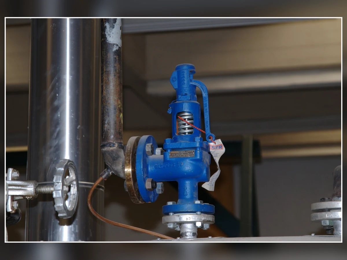
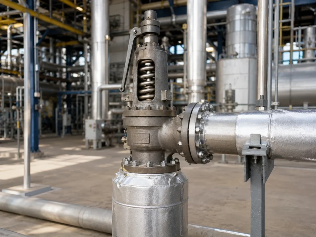
Real spring-loaded safety-valve photograph—not a pilot-operated valve. Used only to show that external appearance cannot establish pop-action or modulating pilot operation.
Image credit: K. Krallis / SV1XV — CC BY-SA 3.0.
Pop-Action vs Modulating: Engineering Comparison at a Glance
| Factor de selección | Pop-action pilot | Modulating pilot | Verification required |
|---|---|---|---|
| Main-valve opening behavior | Rapid transition toward the design opening after pilot actuation | Progressive lift as dome pressure is controlled | Manufacturer lift-versus-pressure curve |
| Relationship to overpressure | Designed for a decisive opening response | Lift responds to overpressure within the selected design | Overpressure required for documented capacity |
| Relief-demand profile | Often suited to rapidly increasing or sustained demand | Often suited to variable demand | Governing relief-case flow profile |
| Product discharged | May pass more flow than a small upset immediately requires | May limit discharge during a smaller event | Actual event profile and outlet system |
| Cycling sensitivity | Can cycle if the valve is oversized or sustainable flow is too low | Can cycle if system dynamics, sensing or valve selection are unsuitable | Dynamic and installed-system review |
| Inlet-loss sensitivity | Still affected by pressure at the valve and pilot sensing point | Still affected; remote sensing may change the control point | Inlet-loss estimate and sensing layout |
| Escape piloto | May vent to atmosphere or another location depending on design | May vent to atmosphere or main-valve outlet depending on design | Manufacturer arrangement and hazardous-release review |
| Contrapresión | Not solved by the action label | Not solved by the action label | Superimposed and built-up back pressure data |
| Medio y fase | Model-specific | Model-specific | Certified or documented fluid basis |
| Dirty or condensing service | Small passages, seats and tubing remain vulnerable | Small passages, seats and tubing remain vulnerable | Contamination, filtration, drainage and heat-tracing review |
| Blowdown y reasentamiento | Específico del diseño | Específico del diseño | Manufacturer settings and performance data |
| Evidencia de capacidad | Required for the complete valve configuration | Required for the complete valve configuration | Selected orifice, fluid basis, pressure and temperature |
| Mantenimiento | Pilot, dome and sensing circuit require inspection | Pilot, modulator, dome and sensing circuit require inspection | Maintenance manual, spares and test procedure |
The table is a screening tool, not a final selector. The same opening label can be implemented differently across product series. The selected manufacturer’s data must confirm the exact mechanism, service range, pressure response and certification basis.
Matriz de selección preliminar
Use this matrix only for preliminary screening. It does not replace relief sizing, manufacturer selection, installed-system review or the adopted code and project specification.
| Engineering condition | Pop-action is the stronger starting point when… | Modulating is the stronger starting point when… | Stop and confirm before selection |
|---|---|---|---|
| Relief-demand profile | The governing demand rises rapidly and is expected to remain high enough to sustain a decisive opening response. | Demand is expected to vary or decline and pressure-responsive lift can reduce unnecessary discharge. | Relief-load profile, governing case and required capacity have not been established. |
| Capacidad requerida | The exact configuration reaches the documented capacity required for the governing case within the available overpressure. | The exact configuration provides the required capacity while allowing controlled lift during smaller events. | Only connection size, set pressure or visual valve size is known. |
| Operating margin and cycling | Manufacturer data and the installed system support stable opening and reseating for the expected pressure history. | Manufacturer curves support progressive lift without unstable cycling for the expected pressure history. | The valve is oversized, the process is pulsating or sustainable relief flow is uncertain. |
| Medium and contamination | The selected pilot is documented for the actual fluid, temperature and contamination controls. | The selected modulating pilot is documented for the actual fluid and small-passage contamination risk is controlled. | Dirty, condensing, freezing, polymerizing or two-phase service has not been reviewed. |
| Sensing and inlet loss | The pilot senses a representative pressure and inlet loss remains acceptable for the selected arrangement. | The sensing arrangement can support the intended pressure-responsive control without delay or blockage. | Remote sensing, isolation, tubing bore, drainage or inlet-loss data are missing. |
| Back pressure and pilot exhaust | The main valve and pilot exhaust arrangement are documented for the superimposed and built-up back pressure. | The main valve and modulating pilot remain stable over the expected outlet pressure range. | Pilot exhaust destination or variable header pressure has not been defined. |
| Operational objective | A decisive response is more important than limiting discharge during a smaller event. | Demand matching and reduced unnecessary release have a defined process value. | The operational objective has not been connected to the governing relief case. |
Start with the Governing Relief Scenario, Not the Pilot Label
The pilot action should follow the governing relief case, not an equipment label. Define the protected equipment, credible scenario, required load, pressure basis and how the demand changes during the event.
For a broader relief-scenario review, use the ZOBAI API 521 pressure-relief-systems guide before comparing pilot actions.
Abrupt and Sustained Relief Demand
A blocked outlet, regulator failure or similar event may create a rapidly increasing load that remains high. A decisive pop response may be useful, but only after capacity and installed-system stability are verified.
Variable or Self-Limiting Relief Demand
Some events rise and then decline as inventory, heat input or upstream flow changes. Modulating action may reduce unnecessary discharge, but the governing maximum load still controls sizing.
Multiple Relief Cases Must Be Checked Separately
Different scenarios can govern capacity, temperature, phase, back pressure or material selection. Do not combine them into one assumed design case without an accepted relief analysis.
Required Capacity and Main-Valve Lift Are Related—but Not Interchangeable
Opening behavior and protection capacity are related but not interchangeable. The governing relief scenario establishes the required load; the selected main-valve/pilot configuration must then have documented capacity for the applicable fluid, relieving pressure and temperature.
Use the ZOBAI Guía de dimensionamiento y capacidad certificada de válvulas de seguridad to separate required load, required area, selected orifice and documented capacity.
Required Load Comes from the Relief Scenario
Required relieving capacity comes from the protected equipment and governing credible scenario—not from set pressure, connection size, visual valve size, pilot label or the fact that a previous valve occupied the same location.
Certified or Documented Capacity Comes from the Selected Valve Configuration
Capacity evidence must match the selected model, orifice, configuration, fluid basis and relieving conditions. Two valves with the same flange size can have different effective flow areas and documented capacities.
Partial Lift Does Not Reduce the Governing Requirement
A modulating valve may operate at partial lift during a smaller event, but the maximum credible case still governs the required capacity. Steam, gas/vapor, liquid, flashing and two-phase capacity bases cannot be substituted for one another without an accepted engineering basis.
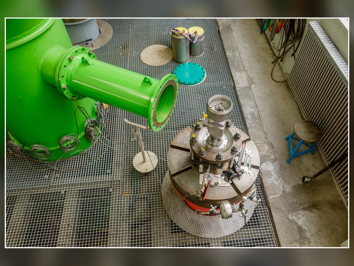
Real safety-relief-valve test-laboratory photograph. It illustrates the need for test and capacity evidence but is not a ZOBAI certificate, capacity result or product claim.
Image credit: CEphoto, Uwe Aranas — CC BY-SA 4.0.
What Each Piece of Evidence Proves—and Does Not Prove
| Evidencia | What it can establish | What it cannot establish by itself | Required follow-up |
|---|---|---|---|
| Prueba de presión de tarado | The valve begins to open at the tested pressure under the stated test conditions. | Required relieving capacity, certified capacity, installed stability or outlet-system adequacy. | Capacity evidence, blowdown/reseat verification and installed-system review. |
| Tamaño y clasificación de la conexión | Physical interface and pressure-temperature rating when material and standard are confirmed. | Effective orifice, coefficient, full configuration capacity or pilot action suitability. | GA, orifice designation, manufacturer datasheet and capacity document. |
| Main-valve lift observation | The valve moved during the observed event or test. | The flow passed, the governing case protected or the certified capacity reached. | Lift-versus-pressure curve, flow basis and capacity documentation. |
| Required relieving-load calculation | The process load that must be discharged for the governing scenario. | That a particular valve or orifice can pass the load. | Valve sizing and configuration-specific capacity comparison. |
| Manufacturer capacity document | Documented capacity for the stated model, orifice, fluid basis, pressure and configuration. | That the installed piping, sensing, back pressure and maintenance condition are acceptable. | Installed-system, material and project-code review. |
| Nameplate or previous model | Identity and selected data for the installed valve, where legible and complete. | That the old selection remains suitable after process, capacity or piping changes. | Management-of-change and replacement verification. |
Capacity control rule
Connection size is not relieving capacity.
Set pressure is not required or certified capacity.
Steam, gas, liquid and two-phase capacity bases are not interchangeable.
A smaller observed event does not reduce the capacity required for the governing credible case.
Operating Margin, Overpressure, Blowdown and Cycling
Operating pressure, set pressure, overpressure, accumulation and reseating pressure describe different parts of the relief cycle. The selected action must remain stable over the actual pressure history; neither modulation nor rapid opening corrects an oversized valve or unsuitable piping.
Operating Close to Set Pressure Requires Verified Performance
When normal pressure approaches set pressure, verify seat tightness, pilot stability and the manufacturer’s recommended operating margin for the exact design.
Modulation Does Not Automatically Eliminate Cycling
A modulating valve can still cycle when the sustainable flow is low, the process pulsates, sensing is delayed or the outlet system interacts with the valve.
Pop-Action Does Not Automatically Guarantee Stable Full Flow
A rapid opening can still chatter or reseat repeatedly if inlet loss, back pressure, sizing or the relief-demand profile is unsuitable.
Dynamic-Behavior Review
| Observed or expected behavior | Posibles contribuyentes | Evidencia a solicitar | Atajo inseguro a evitar |
|---|---|---|---|
| Repeated opening and reseating | Oversized valve, low sustainable flow, narrow operating margin, process pulsation, unsuitable blowdown or outlet interaction. | Pressure history, required flow profile, lift/blowdown curves, as-found records and piping data. | Changing pilot action without checking sizing and system dynamics. |
| Vibración o aleteo | Inlet pressure loss, excessive back pressure, acoustic interaction, mechanical load, sensing delay or insufficient flow. | Inlet/outlet calculations, vibration evidence, support review and manufacturer dynamic guidance. | Treating chatter as a set-pressure adjustment problem only. |
| Leakage near operating pressure | Insufficient operating margin, seat damage, contamination, thermal distortion or unstable pilot control. | Operating history, seat-tightness result, pilot inspection and selected-seat data. | Assuming modulating action alone will improve tightness. |
| Delayed opening | Blocked sensing line, frozen condensate, restricted pilot exhaust, incorrect isolation or contaminated pilot seat. | Tubing inspection, drainage check, functional test and pilot schematic. | Increasing set pressure to mask delayed response. |
Medium, Phase and Contamination Can Override the Preferred Opening Action
A universal rule such as “pop for gas and modulating for liquid” is unsafe. Manufacturer product families differ, and some support both actions across multiple media. Final suitability depends on the exact pilot/main-valve combination, fluid basis, relieving temperature, contamination risk and materials.
Compressible and Incompressible Service Need the Correct Capacity Basis
Gas, vapor, steam and liquid use different capacity bases. Flashing and two-phase service require additional analysis, and lift behavior does not replace that analysis.
Small Pilot Passages Create Contamination and Freezing Risks
Pilot seats, filters, tubing and small passages can be restricted by solids, wax, polymer, condensate, ice or hydrates. Any filtration, clean-pressure source, drainage, insulation or heat tracing must be approved for the selected design and maintained as part of the protection function.
Material Selection Extends Beyond the Main-Valve Body
Review the body, nozzle, disc, piston, guide, spindle, pilot trim, tubing, springs, seals, gaskets and filters. A body grade alone does not establish corrosion, temperature or deposit tolerance for the complete pilot circuit.
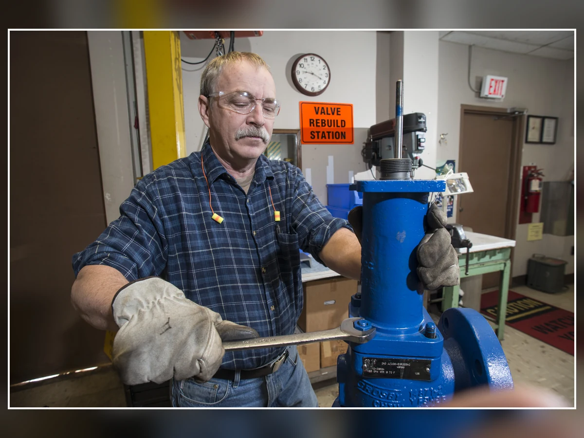
Real pressure-relief-valve rebuild photograph. It supports maintenance and contamination discussion and does not represent a ZOBAI customer project.
Image credit: Savannah River Site / U.S. Department of Energy — Public domain (U.S. federal government work); Commons also records CC BY 2.0 source review.
Medium, Pilot-Circuit and Material Screening
| Condición | Principal riesgo de ingeniería | Parts that require review | Data or control required |
|---|---|---|---|
| Gas o vapor limpio | High velocity, seat leakage, rapid pressure rise and potential cycling. | Pilot seat, main seat, seals, tubing, exhaust route and trim. | Fluid properties, relief profile, operating margin and documented gas/vapor basis. |
| Steam or condensing vapor | Condensation, temperature effects, water accumulation and possible pilot-line blockage. | Pilot passages, tubing, drains, seals, body/trim and any heat-traced components. | Relieving temperature, drainage plan, manufacturer steam scope and maintenance controls. |
| Servicio de líquido | Hydraulic instability, pressure surge, liquid-pocket effects and different capacity basis. | Main-valve trim, pilot configuration, seals, sensing line and outlet drainage. | Liquid properties, viscosity, flashing risk and documented liquid performance. |
| Flashing or two-phase flow | Incorrect capacity basis and unpredictable phase change through the valve and outlet. | Complete valve, inlet piping, outlet system and pilot sensing arrangement. | Specialized relief analysis and manufacturer confirmation for the actual phase behavior. |
| Dirty, waxy or polymerizing medium | Restriction of small pilot passages, filters, seats and tubing. | Pilot, filter, sensing line, dome line, seals and flushing points. | Contamination description, maintenance interval, approved filtration/clean source or alternative configuration. |
| Servicio corrosivo o ácido | Corrosion, stress-corrosion cracking, galling, seal attack and spring degradation. | Body, bonnet, nozzle, disc, guide, spindle, spring, tubing, pilot trim, seals and gaskets. | Composition, temperature, material specification and project-specific corrosion requirements. |
| Freezing or cryogenic exposure | Ice, hydrate or frozen condensate blocking the pilot circuit and changing material behavior. | Pilot, sensing/exhaust tubing, seals, body/trim and support system. | Minimum temperature, heat leak/icing review, drainage or heat tracing where allowed, and model-specific data. |
Inlet Loss, Sensing Location and Pilot Exhaust Must Be Reviewed Together
The pilot responds to the pressure at its actual sensing point. Protected-equipment pressure, main-valve inlet pressure and remote-sense pressure can differ during a relief event, so inlet loss, sensing layout and pilot exhaust must be reviewed as one control system.
El ZOBAI guía de instalación de válvulas de seguridad provides the broader inlet, outlet, support, drainage and discharge-piping checks.
The Pilot Can Only Respond to the Pressure It Actually Senses
Integral sensing normally references pressure near the valve inlet. If inlet pressure falls during discharge, the pilot and main valve may not see the same pressure as the protected equipment.
Remote Sensing Can Help—but Creates Its Own Failure Paths
Remote sensing can move the control point closer to the protected equipment, but adds tubing bore, length, drainage, blockage, isolation, vibration and maintenance failure modes.
Pilot Exhaust Routing Is Part of the Valve Specification
Pilot exhaust may be atmospheric, connected to the main-valve outlet or arranged another manufacturer-approved way. The destination affects hazardous release, exhaust pressure, condensation, freezing and back-pressure exposure. Flowing/non-flowing is a separate design variable from pop/modulating action.
Installation and Pilot-Circuit Do / Don’t List
| Hacer | Por qué es importante | No | Riesgo creado |
|---|---|---|---|
| Confirm the pressure point the pilot actually senses. | The pilot responds to that pressure, not automatically to the protected-equipment pressure. | Assume the valve inlet and protected equipment always see the same pressure. | Opening delay, premature reseating or incorrect control point. |
| Calculate inlet loss for the governing flow and installed geometry. | Inlet loss affects pressure at the valve and can contribute to instability. | Rely on nominal pipe size or a short visual inspection. | Unrecognized restriction or excessive loss. |
| Route remote sensing tubing to avoid blockage, liquid pockets and mechanical damage. | Tubing condition determines how quickly and accurately the pilot senses pressure. | Add long, tortuous or isolated sensing tubing without review. | Delayed or disabled pilot response. |
| Confirm pilot exhaust destination and pressure. | Exhaust routing can affect hazardous release, pilot behavior and back-pressure exposure. | Vent into an enclosed or pressurized location without manufacturer/project approval. | Unsafe release or altered opening/reseating. |
| Independently support heavy outlet piping and manage reaction loads. | Mechanical load can distort the valve and damage pilot tubing. | Use the valve body as the discharge-pipe support. | Misalignment, leakage, vibration or structural damage. |
| Provide drainage and inspect low points. | Accumulated liquid can change outlet resistance and pilot/exhaust behavior. | Allow a closed or undrained discharge pocket. | Built-up back pressure, corrosion or hydraulic loading. |
Back Pressure Still Requires a Manufacturer-Specific Review
Pilot operation does not make outlet pressure irrelevant. Separate superimposed back pressure, built-up back pressure, main-valve outlet pressure and pilot-exhaust pressure, then compare them with the selected manufacturer’s documented limits and capacity/stability basis.
Open the ZOBAI back-pressure and bellows engineering guide for the full superimposed, built-up and outlet-header review.
Main-Valve Balance and Pilot Exhaust Are Separate Checks
The main valve may be pressure-balanced while the pilot exhaust still experiences outlet or header pressure. Both paths must be checked for opening, blowdown, reseating and backflow effects.
Variable Header Pressure Can Change the Relief Cycle
A common header can change pressure as other devices open. Outlet hydraulics, reaction loads, support, drainage and liquid accumulation therefore remain part of the final selection.
Back-Pressure Decision Points
| Back-pressure input | Question to answer | Por qué cambia la selección | Evidencia requerida |
|---|---|---|---|
| Contrapresión superpuesta | What pressure exists at the outlet before the valve opens, and is it constant or variable? | It can affect the main valve, pilot exhaust and opening/reseating behavior. | Normal and upset outlet-pressure range plus selected-model limits. |
| Contrapresión acumulada | What pressure develops while the required flow passes through the discharge system? | It can reduce capacity, change stability and alter the relief cycle. | Outlet hydraulic calculation and manufacturer correction/performance data. |
| Pilot exhaust pressure | Does the pilot vent to atmosphere, the main outlet or another controlled destination? | The pilot can see a pressure different from the main-valve outlet. | Pilot schematic and allowable exhaust-pressure range. |
| Variable common header | Can other relief devices or process events change the outlet pressure during the event? | A variable header can change lift, blowdown and cycling behavior. | Header scenarios, simultaneous-load basis and transient review where needed. |
| Drainage and liquid accumulation | Can condensate or rainwater collect in the outlet system? | Liquid head and slugging can add resistance and mechanical load. | Drain location, slope, low-point and support review. |
When Pop-Action Is Usually the Better Starting Point
Pop-action is usually the stronger starting point when the governing event demands a rapid transition toward a large opening and the relief load is expected to remain high.
Strong Fit Indicators
Strong indicators are a fast-rising sustained demand, a defined need for decisive response and manufacturer evidence that the exact valve reaches the required capacity and remains stable.
Conditions That Still Require Caution
Recheck low sustainable flow, oversized orifice, pulsation, contamination, sensing delay, variable back pressure and incomplete blowdown data.
Do not finalize pop-action when…
The relief demand is small or uncertain relative to the selected orifice and stable sustainable flow has not been shown.
Pilot passages are exposed to contamination or freezing without an approved control strategy.
The manufacturer has not provided the lift, capacity, blowdown and service basis for the exact configuration.
When Modulating Action Is Usually the Better Starting Point
Modulating action is usually the stronger starting point when the relief demand changes during the event and pressure-responsive lift has a defined process or release-control benefit.
Strong Fit Indicators
Strong indicators are variable demand, a need to limit unnecessary discharge and manufacturer curves showing stable progressive lift while preserving the full governing capacity.
Conditions That Still Require Caution
Recheck contamination, sensing delay, unstable process pressure, required full lift, blowdown, back pressure and whether modulation is being used to mask oversizing.
Do not finalize modulating action when…
It is being used as a substitute for correct sizing, acceptable inlet loss or a stable discharge system.
The process demand is not understood well enough to justify pressure-responsive lift.
Full required capacity, cycling behavior, contamination tolerance and reseating have not been documented.
Common Selection Errors and Their Failure Chains
Selection errors usually form a chain: an incomplete relief or installation input produces an unsupported configuration choice, which then appears as cycling, delayed opening, insufficient pressure control, leakage or slow reseating. Use the following matrix to identify the next engineering check; do not treat it as permission for unapproved field adjustment.
Observed Behavior, Likely Causes and Checks
| Observed behavior | Causas posibles | Immediate engineering checks | Escalation boundary |
|---|---|---|---|
| La válvula se abre y se cierra repetidamente | Oversizing, low sustainable flow, process pulsation, inlet loss, outlet pressure interaction or unsuitable blowdown. | Review required load, selected orifice, pressure history, inlet/outlet calculations and manufacturer curves. | Do not continue repeated cycling without engineering review; mechanical damage and leakage may worsen. |
| Pilot-operated valve does not open at the expected system condition | Sensing blockage, incorrect isolation, frozen condensate, restricted exhaust, set-pressure error or pilot damage. | Confirm safe system status, inspect the sensing/exhaust route and review test records. | Remove from protective service or establish an approved alternative protection path where required by the owner/code. |
| Valve opens but pressure remains uncontrolled | Insufficient capacity, wrong fluid basis, excessive inlet loss, high built-up back pressure or restricted discharge. | Compare required load with documented capacity and check installed piping. | Do not assume a larger connection or more lift will solve the governing case. |
| Fuga después de un evento de alivio | Seat damage, contamination, misalignment, thermal distortion, unstable cycling or debris. | Inspect seat/pilot condition, review event pressure history and perform the specified tests. | Field adjustment without an approved procedure can change set pressure and traceability. |
| Slow or inconsistent reseating | Pilot refill restriction, exhaust pressure, contamination, wrong blowdown setting or process pressure recovery. | Review pilot circuit, outlet pressure and manufacturer blowdown basis. | Do not apply a generic blowdown value across manufacturers or services. |
Composite Engineering Scenarios for Selection Training
How to use the scenarios
These are composite engineering scenarios for training, not ZOBAI customer projects or performance claims.
Each preliminary preference remains conditional until capacity, pressure, media, sensing, back pressure, materials and manufacturer evidence are complete.
Scenario 1 — Rapid Gas-System Upset with Sustained High Relief Demand
A gas-system upset creates a fast-rising load that remains high. Pop-action is the preliminary direction, subject to required capacity, inlet loss, back pressure, sensing and exact manufacturer data.
Scenario decision record
Preliminary direction: pop-action may be the stronger starting point because the governing demand rises rapidly and remains substantial.
Still required: governing load, documented capacity, overpressure basis, inlet loss, outlet pressure, sensing location, pilot exhaust and exact manufacturer configuration.
Scenario 2 — Variable Process Upset Where Demand Declines During the Event
The load rises and then declines as the process condition changes. Modulating action is the preliminary direction, provided the valve still protects the maximum credible case and does not cycle.
Scenario decision record
Preliminary direction: modulating action may be the stronger starting point because the relief demand changes during the event.
Still required: full governing-case capacity, minimum stable response, cycling/blowdown behavior, process pressure recovery and discharge-system review.
Scenario 3 — Dirty or Condensing Service with Long Sensing Tubing
Dirty or condensing service and long sensing tubing create blockage and response-delay risks. Neither action should be selected until the pilot circuit, drainage, filtration and maintenance controls are accepted.
Scenario decision record
Preliminary direction: neither action should be selected until the pilot circuit can be protected from blockage, condensation and response delay.
Still required: contamination description, tubing layout, drainage, filtration or clean-pressure-source feasibility, maintenance access and manufacturer limits.
RFQ Data Required Before Selecting Pop or Modulating Action
Before quotation, confirm enough information to select the complete valve, not only the pilot label.
Datos de proceso y alivio
| Required field | Por qué cambia la decisión |
|---|---|
| Equipo protegido | Establishes the applicable equipment code and protection objective |
| Escenario de alivio principal | Defines the demand profile and required load |
| Medio y fase | Controls sizing basis, pilot suitability and materials |
| Fluid composition and contamination | Identifies corrosion, plugging, polymerization, freezing or seal risks |
| Presión de operación | Establishes normal margin below the opening condition |
| MAWP/design pressure | Establishes equipment limit according to the adopted design basis |
| Presión de tarado | Defines the valve adjustment target; does not prove capacity |
| Allowable overpressure/accumulation | Defines available pressure for valve capacity and system control |
| Capacidad de alivio requerida | Establishes the flow that must be passed |
| Base de cálculo de capacidad | Allows the manufacturer to verify assumptions |
| Temperatura de alivio | Changes fluid properties, materials, seals and capacity |
Installed-System Data
| Required field | Por qué cambia la decisión |
|---|---|
| Inlet connection and piping | Affects fit, inlet loss and stability |
| Outlet connection and piping | Affects back pressure, reaction and drainage |
| Estimated superimposed back pressure | Defines outlet pressure before opening |
| Estimated built-up back pressure | Defines outlet pressure during flow |
| Integral or remote sensing | Defines the pilot control point |
| Sensing-line length, bore and routing | Affects delay, plugging and condensation |
| Pilot exhaust destination | Affects safety and pilot performance |
| Ambient conditions | Identifies freezing, heat or corrosion risks |
| Orientation, support and access | Affects installation and maintenance |
Valve, Material and Documentation Requirements
| Required field | Por qué cambia la decisión |
|---|---|
| Main-valve and pilot materials | Confirms compatibility across all exposed parts |
| Tipo de asiento y sello | Affects leakage, temperature and media suitability |
| Pop or modulating preference | Records the preliminary choice, not the final decision |
| Flowing or non-flowing pilot requirement | Defines a separate pilot-architecture decision |
| Código aplicable y edición adoptada | Controls sizing, certification, testing and marking |
| Documentación de capacidad | Confirms the offered configuration can protect the case |
| Set-pressure and seat-tightness tests | Defines test scope; neither replaces capacity verification |
| Functional test requirements | Confirms pilot and main-valve operation where applicable |
| Material records and traceability | Supports procurement and QA review |
| GA, datasheet and manuals | Supports fit, installation and maintenance review |
| Spare-parts requirement | Affects lifecycle support and lead time |
| Existing nameplate/datasheet | Required for replacement equivalence review |
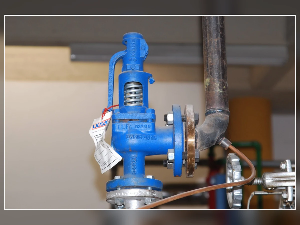
Real spring-loaded safety-valve photograph—not a pilot-operated valve. Used only to show that a replacement cannot be approved from appearance, flange size or set pressure alone.
Image credit: K. Krallis / SV1XV — CC BY-SA 3.0.
Matriz de pruebas y documentación
| Elemento | What it verifies | What the RFQ should state | What it does not replace |
|---|---|---|---|
| Set-pressure / functional test | Opening pressure and functional response under the stated test procedure. | Test medium, acceptance basis, witness scope, report format and as-left requirement. | Relief sizing, certified capacity or installed-system review. |
| Prueba de estanqueidad del asiento | Leakage performance at the specified test pressure and method. | Applicable procedure/standard, seat type, acceptance criterion and report. | Set-pressure verification or capacity evidence. |
| Capacity certificate or manufacturer capacity document | Capacity basis for the selected model, orifice, configuration and fluid. | Exact configuration, pressure/temperature basis, fluid basis and required document status. | Confirmation that inlet/outlet piping and back pressure are acceptable. |
| Registros de materiales | Specified materials and traceability for the stated parts and scope. | Body, nozzle, disc, guide, spring, pilot trim, tubing, seals and any project-specific records. | Media compatibility unless the complete service condition is reviewed. |
| GA / dimensional drawing | Connections, overall dimensions, orientation, mass and accessory arrangement. | Exact inlet/outlet standard, pilot/sensing/exhaust connections and support/access needs. | Capacity or pressure-relief-system adequacy. |
| Nameplate and marking review | Identity and required marked data for the delivered valve. | Required code/project markings and any limitations. | Automatic proof that every project or jurisdiction accepts the valve. |
| Manual de instalación y mantenimiento | Approved installation, operation, inspection and service instructions. | Model-specific manual, spare-parts list and pilot-circuit maintenance requirements. | Project-specific piping design or maintenance interval determination. |
Flujo de trabajo de verificación de reemplazo
| Paso | Required evidence | Por qué se necesita | Do not approve replacement when… |
|---|---|---|---|
| 1. Identify the installed valve | Nameplate, manufacturer, model, serial number, set pressure, orifice/capacity marking and photos. | Establishes what is installed and whether the available data are complete. | Identity or marked data are missing or inconsistent. |
| 2. Reconfirm the protection basis | Protected equipment, MAWP/design pressure, governing relief scenario and required capacity. | Checks whether the original selection remains valid after process changes. | The process or relief case changed without a new calculation. |
| 3. Compare hydraulic and mechanical fit | Connection standard/rating, dimensions, mass, orientation, inlet/outlet piping and supports. | Prevents a dimensional match from becoming an unstable or overloaded installation. | Only flange size is matched. |
| 4. Compare pilot and service compatibility | Pop/modulating action, sensing, exhaust, medium/phase, temperature, contamination and materials. | Confirms the pilot system can function in the actual service. | The proposed pilot is supported only by a generic product-family statement. |
| 5. Verify capacity and documents | Selected orifice, documented capacity, fluid basis, tests, GA, materials and adopted-code/project documents. | Confirms protection capability and procurement traceability. | Capacity is inferred from connection size, previous model or set pressure. |
| 6. Control the change | Engineering approval, management-of-change record, installation checks and post-installation test/inspection plan. | Ensures the replacement remains part of the pressure-protection system rather than a purchasing-only substitution. | No competent engineering owner has accepted the change. |
Final Selection Workflow
Final Preliminary Decision Summary
| Factor de decisión | Pop-action direction | Modulating direction | Confirmación requerida |
|---|---|---|---|
| Relief-demand profile | Rapidly increasing and sustained governing demand. | Variable or declining demand where pressure-responsive lift has process value. | Approved relief scenarios and required load profile. |
| Capacidad | Exact configuration reaches required documented capacity within available overpressure. | Exact configuration still reaches the full governing capacity while modulating smaller events. | Selected orifice, fluid basis, relieving pressure/temperature and manufacturer evidence. |
| Sensing and inlet loss | Representative sensing and acceptable inlet-loss behavior for decisive opening. | Representative sensing without delay or blockage for stable progressive control. | Integral/remote sensing layout, tubing, isolation, inlet calculation and pilot schematic. |
| Medium and contamination | Selected pop pilot documented for the real fluid and contamination controls. | Selected modulating pilot documented for the real fluid and small-passage risks. | Phase, composition, temperature, deposits/freezing risk, materials and maintenance. |
| Back pressure and final evidence | Main valve and pilot exhaust remain within documented limits. | Progressive operation remains stable over the expected outlet-pressure range. | Superimposed/built-up back pressure, exhaust destination, curves, tests, code and project documents. |
- Identificar el equipo protegido y el escenario de alivio dominante. Do not begin with the valve catalog.
- Determine the required relieving load and capacity basis. Confirm medium, phase, relieving pressure and relieving temperature.
- Define the pressure terms. Separate operating pressure, MAWP/design pressure, set pressure, overpressure, accumulation and blowdown.
- Characterize the relief-demand profile. Decide whether it is abrupt and sustained, variable, self-limiting or affected by multiple cases.
- Screen pop and modulating action. Use the process profile to identify the stronger starting point.
- Review medium, contamination and materials. Include the pilot, tubing, seals and main valve.
- Review inlet loss, sensing and pilot exhaust. Confirm the pressure the pilot will actually sense.
- Revisar la contrapresión superpuesta y acumulada. Include the pilot exhaust destination and common header.
- Compare manufacturer performance data. Review lift, capacity, overpressure, blowdown, operating margin and service limits for the exact configuration.
- Confirm tests, certification and documents. A standard name alone does not complete the specification.
- Complete project/code review before final selection. The final valve depends on real service data, adopted code, local regulatory requirements and manufacturer confirmation.
Final engineering confirmation
The selected action is only one part of the complete pressure-relief-device specification.
Final selection depends on real operating data, the governing relief scenario, manufacturer performance for the exact configuration, the adopted code edition, project requirements and local regulatory review.
Where any critical input is missing, the correct status is “to be confirmed,” not an assumed valve recommendation.
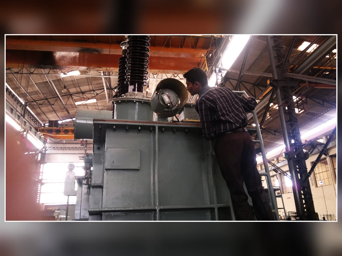
Real pressure-relief-valve inspection photograph. It is a contextual final-verification asset and must not be used as the TechArticle Hero ImageObject.
Image credit: Shriram — CC BY-SA 3.0.
Preguntas Frecuentes
¿Cuál es la principal diferencia entre las válvulas de seguridad pilotadas de acción rápida y las modulantes?
Una piloto de acción rápida reduce rápidamente la presión de la cámara superior para que la válvula principal se mueva rápidamente hacia su apertura de diseño. Una piloto modulante controla la presión de la cámara superior de forma progresiva, de modo que la elevación de la válvula principal responde al exceso de presión del sistema. El rendimiento exacto depende del fabricante y modelo seleccionados.
¿La acción de apertura brusca significa siempre capacidad certificada completa a la presión de ajuste?
N.º La acción de apertura súbita describe una característica de apertura rápida. La capacidad certificada o documentada, la sobrepresión necesaria para alcanzarla y la base de fluido aplicable deben confirmarse para la configuración exacta de la válvula.
¿Los pilotos de acción rápida son solo para gas y los pilotos modulantes solo para líquido?
No existe una regla universal. Algunas series de productos restringen los pilotos de acción rápida a gas, mientras que otras series ofrecen pilotos de acción rápida o modulantes para vapor o líquido. Utilice los datos de servicio y certificación del fabricante seleccionado.
¿Puede una válvula pilotada modulante reducir la pérdida de producto durante cada evento de alivio?
No necesariamente. La modulación puede limitar el caudal durante eventos por debajo de la demanda máxima, pero la descarga total también depende de la duración del evento, la respuesta del proceso, el dimensionamiento de la válvula, la presión de salida y la carga de alivio gobernante.
¿Qué acción piloto tiene menos probabilidades de producir aleteo o ciclado?
Ninguna acción es automáticamente inmune. La estabilidad depende del dimensionamiento, el flujo sostenible, la pérdida de presión en la entrada, la dinámica de detección, la contrapresión, el perfil de demanda de alivio y el estado de la válvula. Se requieren datos de rendimiento del fabricante y revisión del sistema instalado.
¿Cómo afectan la pérdida de presión de entrada y la detección remota a la elección?
Inlet loss can make pressure at the valve differ from pressure at the protected equipment. Remote sensing can move the pilot’s control point, but the sensing line introduces blockage, delay, condensation, isolation and damage risks that must be engineered.
What data must be provided before a manufacturer can select the pilot action?
Provide the protected equipment, governing relief scenario, medium and phase, operating pressure, MAWP/design pressure, set pressure, allowable overpressure, required capacity, relieving temperature, back pressure, inlet/outlet piping, sensing location, pilot exhaust, materials, code and documentation requirements.
Official Technical References and Selection Limitations
The following primary sources support the general comparison and define the standards context. Manufacturer examples are cited only to show that product families implement pop-action and modulating behavior differently; their pressure, temperature, media, overpressure, blowdown, capacity and approval ranges must not be transferred to another manufacturer or model.
Primary Sources Used for Technical Review
| Fuente primaria | Lo que soporta | Límite |
|---|---|---|
| Emerson Birkett Safeset | Current product-family page confirms that Safeset includes pop-action and modulating pilot-operated safety relief valves. | Use only as an attributed manufacturer example; its pressure, media, blowdown and performance ranges are product-specific. |
| Baker Hughes Consolidated 3900/3900 TM | Current product page documents optional pop or modulating pilot constructions within the 3900/3900 TM family. | Applicability depends on the exact main valve, pilot, soft goods, fluid basis and ordered configuration. |
| LESER Pilot-Operated Pressure Relief Valves | Current product-family overview distinguishes pilot-operated product options and directs users to model-specific information. | Series 810/811 and 820/821 data remain manufacturer- and model-specific. |
| API 520 Parte I | The official API page identifies the 10th Edition as the current published Part I for sizing and selection in its stated scope. | Confirm the edition adopted by the project; committee work on a future edition is not a published standard. |
| Norma API 521 | Official API scope covers guidance for pressure-relieving and vapor-depressuring system design. | Relief scenarios, simultaneous loads, disposal systems and adopted editions remain project-specific. |
| ISO 4126-4:2013 | The official ISO page identifies Part 4 as the pilot-operated safety-valve product standard and states that it was reviewed and confirmed in 2025. | ISO states that Part 4 is a product standard, not an application standard; project and jurisdictional adoption still require confirmation. |
| ASME BPVC Section XIII — 2025 | The official 2025 page covers overpressure protection, pressure-relief devices, testing, marking, installation and capacity/flow-resistance certification. | Citing Section XIII does not prove that any ZOBAI or other valve carries a specific ASME designation. |
Technical source review: August 6, 2026. Verify the edition adopted by the project and recheck official sources before any later revision.
This article supports preliminary selection and RFQ preparation only. It does not replace a relief calculation, manufacturer sizing, adopted-code review, project specification, inspection authority or local regulatory approval.
Send the Relief Scenario and Pilot-System Data for Review
Pop-action versus modulating cannot be selected from set pressure and flange size alone. Send the protected equipment, governing relief scenario, medium and phase, composition and contamination risk, operating pressure, MAWP or design pressure, set pressure, allowable overpressure or accumulation basis, required relieving capacity and calculation basis, relieving temperature, superimposed and built-up back pressure, inlet and outlet piping, integral or remote sensing arrangement, pilot exhaust destination, materials and seals, adopted code/project requirements, required tests and documents, and any existing valve nameplate, datasheet, GA, inspection history or relief calculation.