Comparación técnica de válvulas de seguridad pilotadas con y sin flujo continuo. Las válvulas de seguridad pilotadas con flujo y sin flujo se diferencian principalmente en el circuito piloto durante el alivio estable. Un diseño con flujo normalmente mantiene una purga o flujo controlado; un diseño sin flujo normalmente detiene el flujo piloto continuo después de que la válvula principal alcanza una condición de alivio estable, aunque puede ocurrir flujo transitorio durante la actuación, el ajuste de elevación, el reasentamiento y la recarga de la cámara. La distinción es importante cuando la descarga del piloto, las emisiones, la humedad, la contaminación, la formación de hielo, la contrapresión o el alivio de larga duración afectan la especificación. No define la acción de apertura total o modulante, la ubicación de la toma de presión ni la capacidad de alivio. La presión de ajuste y el tamaño de conexión tampoco demuestran que la válvula seleccionada tenga una capacidad documentada adecuada. Antes de la selección, confirme el equipo protegido, el escenario de alivio, el medio y la fase, la presión de operación, la MAWP o presión de diseño, la presión de ajuste, la capacidad requerida, la temperatura de alivio, la contrapresión superpuesta y acumulada, la fuente de toma de presión, el destino de la descarga, los materiales y los documentos requeridos. Envíe estas condiciones para una revisión de ingeniería.

Comparación técnica de válvulas de seguridad pilotadas
Las válvulas de seguridad pilotadas con flujo y sin flujo se diferencian principalmente en el circuito piloto durante el alivio estable. Un diseño con flujo normalmente mantiene una purga o flujo controlado; un diseño sin flujo normalmente detiene el flujo piloto continuo después de que la válvula principal alcanza una condición de alivio estable, aunque puede ocurrir flujo transitorio durante la actuación, el ajuste de elevación, el reasentamiento y la recarga de la cámara. La distinción es importante cuando la descarga del piloto, las emisiones, la humedad, la contaminación, la formación de hielo, la contrapresión o el alivio de larga duración afectan la especificación. No define la acción de apertura total o modulante, la ubicación de la toma de presión ni la capacidad de alivio. La presión de ajuste y el tamaño de conexión tampoco demuestran que la válvula seleccionada tenga una capacidad documentada adecuada. Antes de la selección, confirme el equipo protegido, el escenario de alivio, el medio y la fase, la presión de operación, la MAWP o presión de diseño, la presión de ajuste, la capacidad requerida, la temperatura de alivio, la contrapresión superpuesta y acumulada, la fuente de toma de presión, el destino de la descarga, los materiales y los documentos requeridos. Envíe estas condiciones para una revisión de ingeniería.
Válvulas de seguridad pilotadas de flujo continuo vs. sin flujo continuo: respuesta rápida
Flujo continuo o sin flujo continuo describe el comportamiento del medio de proceso a través del circuito piloto. Un piloto de flujo continuo normalmente mantiene un flujo diseñado durante el estado de alivio estable correspondiente; un piloto sin flujo continuo normalmente detiene el flujo continuo del piloto en la elevación estable. Ninguno de los términos define la acción de la válvula principal, la ubicación de detección, el destino de la descarga o la capacidad de alivio.
Un piloto sin flujo continuo puede pasar un volumen transitorio mientras actúa, cambia la presión del domo o represuriza el domo. No debe describirse como de flujo cero, cero emisiones o libre de mantenimiento.
Revise la arquitectura seleccionada dentro del válvula de seguridad pilotada sistema completo en lugar de tratar la clasificación del flujo del piloto como una especificación completa.
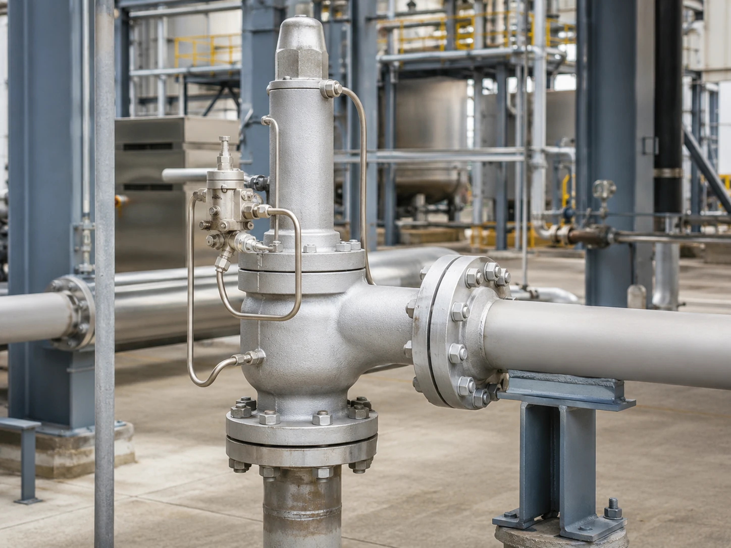
Visualización conceptual realista. La geometría final de la válvula, la detección, el enrutamiento de la descarga, el rango de presión y la capacidad documentada deben confirmarse contra el modelo seleccionado.
Matriz de selección preliminar
Esta matriz es una herramienta de selección preliminar, no una recomendación de modelo. Identifica las preguntas que deben resolverse antes de especificar un piloto de flujo continuo o sin flujo continuo.
Desplácese horizontalmente para revisar todas las columnas.
| Condición de servicio o proyecto | Por qué es importante | Revisión de piloto de flujo continuo | Revisión de piloto de flujo no continuo | Punto de control de ingeniería |
|---|---|---|---|---|
| La descarga atmosférica local del piloto está restringida | La ventilación del piloto puede no ser aceptable para medios peligrosos, valiosos o regulados. | Confirmar el flujo continuo del piloto y el enrutamiento aprobado. | Confirmar la descarga transitoria y la condición estable del modelo seleccionado. | Mantener la selección en espera hasta que se definan el destino de la descarga y los efectos de la contrapresión. |
| Los eventos de alivio pueden prolongarse | La larga duración puede aumentar la pérdida de medio del piloto y la carga del sistema de descarga. | Solicitar datos de ciclo de operación y flujo del piloto. | Confirmar cuándo se detiene el flujo continuo y cómo se controla la elevación. | La duración por sí sola no decide la arquitectura; la capacidad y la estabilidad siguen siendo determinantes. |
| Gas húmedo, baja temperatura ambiente o riesgo de hidratos | Las restricciones, filtros, líneas de sensado y vías de escape pueden congelarse o acumular líquido. | Revise el enfriamiento por expansión, el drenaje, la calefacción y los límites de temperatura. | Revise la expansión transitoria, la recarga del domo y las líneas de sensado húmedas. | Mantenga hasta que se confirmen el control de humedad y la temperatura mínima. |
| Medio sucio, polimerizante o con partículas | Los pasajes pequeños y los asientos pueden obstruirse, pegarse o erosionarse. | Evalúe la exposición continua de restricciones y filtros. | Evalúe los asientos, las vías transitorias, el filtrado y la contaminación del domo. | Un filtro por sí solo no hace que el servicio sea aceptable. |
| Presión de salida variable o colector de descarga común | La presión de salida puede alterar el equilibrio de fuerzas del piloto y de la válvula principal. | Confirme cómo actúa la presión de salida sobre el circuito de escape y de la cámara superior. | Confirmar el control estable de alivio, el reasentamiento y el comportamiento de contracorriente. | Separar la contrapresión superpuesta y la contrapresión acumulada. |
| Se requiere detección remota. | El trazado de la línea de detección, la pérdida de presión, la pulsación, el drenaje y el aislamiento pueden afectar el funcionamiento. | Confirmar que la señal remota es compatible con el circuito piloto seleccionado. | Confirmar el control del domo y la respuesta transitoria con la disposición de detección remota. | No inferir la idoneidad de la detección remota a partir de la clasificación del flujo piloto. |
| Es posible el servicio con líquido, vaporización o dos fases. | El comportamiento de las fases afecta la capacidad, la dinámica del piloto y la estabilidad de la descarga. | Se requiere la aprobación explícita del fabricante para la fase real y el caso de alivio. | Se requiere la aprobación explícita del fabricante para la fase real y el caso de alivio. | La comparación de flujo/no flujo por sí sola es insuficiente. |
Cómo una válvula de seguridad pilotada controla la válvula principal
Válvula principal, piloto y presión del domo
Un sistema típico incluye la válvula de alivio principal, el piloto, el domo o cámara de control, la ruta de detección, el tubo y la descarga del piloto. Por debajo de la presión de ajuste, la presión del proceso normalmente mantiene la presión del domo y la fuerza de cierre de la válvula principal.
A la presión de ajuste, el piloto cambia la ruta de presión del domo para que la presión de entrada pueda abrir la válvula principal. Cuando la presión cae hacia la presión de cierre del piloto, el domo se represuriza y la válvula principal se asienta nuevamente.
Presión de detección y descarga del piloto
La presión puede detectarse integralmente o de forma remota. La descarga del piloto puede ir a la atmósfera, a la salida principal u otra ruta cerrada aprobada; ninguna de estas opciones está determinada por la clasificación de flujo o no flujo.
La operación del piloto no reemplaza la verificación de capacidad
La respuesta a la presión de ajuste no demuestra que la válvula pueda pasar la carga de alivio gobernante. Confirme la capacidad requerida, el orificio seleccionado y la capacidad documentada por separado; el tamaño de la conexión no es una base de capacidad. Ver dimensionamiento de válvulas de seguridad y capacidad de alivio certificada.
Capacidad requerida, válvula seleccionada y evidencia son diferentes
La arquitectura del piloto controla la válvula principal, pero no reemplaza la cadena de selección de capacidad. Cada elemento a continuación responde una pregunta de ingeniería diferente.
Los valores de capacidad para vapor, aire o gas, líquido y dos fases no son intercambiables. La base de capacidad seleccionada debe coincidir con el medio de alivio real, la fase, la presión, la temperatura, la contrapresión y el método de cálculo aplicable.
Desplácese horizontalmente para revisar todas las columnas.
| Elemento | Lo que representa | Evidencia requerida | Qué No Demuestra |
|---|---|---|---|
| Capacidad de alivio requerida | Carga de alivio del escenario de sobrepresión dominante. | Base de cálculo, propiedades del fluido, fase, presión y temperatura de alivio. | No selecciona el tamaño de conexión ni el tipo de piloto. |
| Área de flujo requerida | Área efectiva mínima calculada para la base de dimensionamiento. | Método aplicable, coeficientes, contrapresión y suposiciones del fluido. | No demuestra que un orificio comercial tenga capacidad documentada suficiente. |
| Orificio o diseño de válvula seleccionado | Geometría del fabricante elegida para cumplir con la carga requerida. | Hoja de datos del modelo, designación del orificio y documentación de capacidad. | No demuestra la idoneidad de temperatura, material, escape o contrapresión. |
| Capacidad documentada o certificada | Rendimiento publicado o documentado bajo las condiciones indicadas. | Tabla de capacidad, certificado o registro de cálculo requerido por el proyecto. | No sustituye la verificación del medio real y las condiciones de alivio. |
| Tamaño de conexión de entrada y salida | La interfaz de tubería y la conexión bridada o roscada. | Disposición general y especificación de conexión. | La dimensión de la conexión por sí sola no demuestra la capacidad de alivio. |
| Prueba de presión de tarado | La respuesta de presión del piloto y la válvula bajo el procedimiento de prueba. | Registro de prueba calibrado y criterios de aceptación aplicables. | No demuestra de forma independiente la capacidad en campo, la idoneidad de fase ni el rendimiento con contrapresión. |
Los cuatro estados operativos que los compradores deben comparar
Desplácese horizontalmente para revisar todas las columnas.
| Estado operativo | Revisión de piloto de flujo continuo | Revisión de piloto de flujo no continuo | Verificación específica del modelo |
|---|---|---|---|
| Funcionamiento normal cerrado | Determinar si existe una ruta de purga o circulación diseñada. | Determinar si el circuito piloto se vuelve estático después de la presurización del domo. | Disposición de suministro, domo y asiento de escape. |
| Actuación del piloto | Identificar cómo cambia la trayectoria del flujo del piloto. | Identificar el volumen transitorio que pasa a través del piloto. | Secuencia de actuación y trayectoria de despresurización del domo. |
| Alivio estable de la válvula principal | Confirmar si el flujo del piloto continúa. | Confirmar que el flujo continuo del piloto se detiene en la elevación estable. | Esquema de funcionamiento del fabricante. |
| Reasentamiento y represurización del domo | Confirmar cómo se reconstruye la presión del domo. | Confirmar el caudal de recarga transitorio y el rearme del piloto. | Presión de cierre, respuesta de blowdown y contrapresión. |
Estado 1: Operación normal cerrada
Por debajo de la presión de ajuste, confirmar el estado del asiento del piloto, el drenaje de la línea de detección, la condición del filtro y una posible fuga en el domo.
Estado 2: Actuación del piloto
A la presión de ajuste, el piloto restringe el suministro del domo y reduce la presión del domo. Normalmente ocurre algo de flujo del piloto durante esta transición, incluso en un diseño sin flujo.
Estado 3: Alivio estable de la válvula principal
Este estado separa las clasificaciones: los diseños con flujo mantienen la ruta del piloto prevista, mientras que los diseños sin flujo detienen el flujo continuo del piloto en elevación estable.
Estado 4: Reasiento y represurización del domo
A medida que la presión cae, el piloto restablece la presión del domo. Un piloto sin flujo aún puede pasar caudal de recarga transitorio antes de que la válvula principal se cierre.
¿Qué es un piloto con flujo?
Un piloto con flujo mantiene una ruta de medio de proceso diseñada durante el estado de alivio estable relevante. El flujo es pequeño en comparación con la descarga principal, pero puede ser importante para medios tóxicos, inflamables, corrosivos, valiosos o con humedad. Fundamentos operativos de Baker Hughes describen los pilotos de flujo continuo y de flujo no continuo como un eje de clasificación.
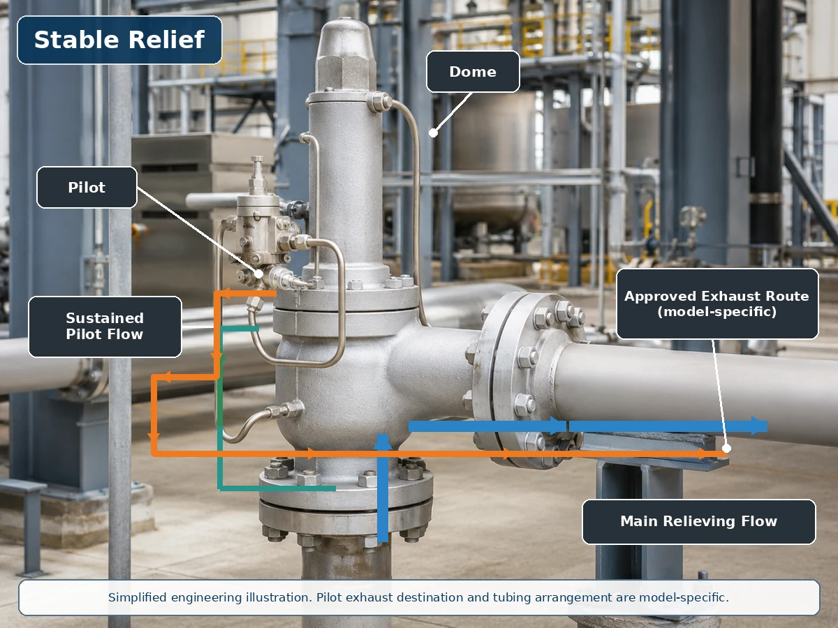
Ilustración técnica simplificada basada en una instalación real de válvula. Las rutas reales de suministro del piloto, domo y escape son específicas del modelo.
Trayectoria del flujo durante el alivio de la válvula principal
Durante el alivio, el flujo continuo del piloto puede ventear o regular la presión del domo. Confirme la base del flujo del piloto, el destino del escape y las consecuencias de servicio en lugar de tratar el flujo como un descarte automático.
Escape del piloto y represurización del domo
Confirme si el escape va a la atmósfera, a la salida o a otro sistema aprobado, y si la presión de salida, el condensado, el drenaje, la calefacción o la protección invernal lo afectan.
¿Qué es un piloto de flujo no continuo?
Un piloto de flujo no continuo alcanza una condición estable en la que el flujo continuo del medio de proceso a través del piloto se detiene mientras la válvula principal puede permanecer abierta. Los asientos internos, los elementos de retroalimentación y los detalles de control del domo son específicos del modelo. Manual de la Serie 800 de Emerson describe esta condición de alivio estable y también señala el flujo transitorio cuando el piloto cambia la elevación.

Ilustración técnica simplificada. Sin flujo continuo no significa cero flujo transitorio, cero fugas o cero emisiones.
Actuación transitoria y despresurización de la cámara
A la presión de ajuste, la piloto reduce la presión de la cámara; una pequeña cantidad de medio de la cámara o del proceso puede pasar durante esta transición.
Alivio estable sin flujo continuo de la piloto
En elevación estable, la piloto puede aislar la alimentación y la descarga, de modo que el flujo continuo de la piloto se detiene. Esto puede reducir el consumo sostenido de medio, pero no demuestra cero fugas ni elimina los riesgos de contaminación y congelación.
Reajuste y recarga de la cámara
Cuando la presión cae, la vía de alimentación de la cámara se reabre y se produce un flujo transitorio de recarga antes de que la válvula principal se cierre.
Comparación entre piloto con flujo y sin flujo
Desplácese horizontalmente para revisar todas las columnas.
| Factor técnico | Piloto con flujo | Piloto sin flujo | Pregunta de selección |
|---|---|---|---|
| Flujo piloto estable durante el alivio | Se mantiene normalmente durante la fase de control correspondiente. | Normalmente ausente en la elevación estable de la válvula principal. | ¿Qué muestra el esquema de funcionamiento seleccionado? |
| Flujo transitorio del piloto | Presente. | Presente durante el movimiento del piloto o el control de la cámara. | ¿Qué volumen y ruta de escape se aplican? |
| Pérdida de medio de proceso | Puede ser mayor a través del piloto durante el alivio sostenido. | Generalmente menor a través del piloto en alivio estable. | ¿El medio es peligroso, valioso o controlado? |
| Emisiones a la atmósfera | Posible si el escape del piloto está abierto a la atmósfera. | Aún posible durante la actuación si se ventila abiertamente. | ¿Dónde termina la descarga del piloto? |
| Exposición a contaminantes | Depende de la trayectoria continua, restricciones y filtrado. | Depende de los asientos, pasajes, flujo transitorio y filtrado. | ¿Es el medio adecuado para el piloto seleccionado? |
| Congelación y formación de hielo | La expansión continua puede ser relevante. | La expansión transitoria y las líneas de detección húmedas aún pueden congelarse. | ¿Qué temperatura mínima y condición de humedad se aplican? |
| Exposición a contrapresión | El enrutamiento de la descarga puede afectar el control del piloto. | El trazado de la descarga también puede afectar al control del piloto. | ¿La descarga del piloto está conectada a la salida? |
| Acción de apertura total o modulante | Clasificación separada. | Clasificación separada. | ¿Qué acción de la válvula principal se requiere? |
| Capacidad de alivio | No determinado por el tipo de flujo del piloto. | No determinado por el tipo de flujo del piloto. | ¿La capacidad documentada es adecuada para el caso de alivio? |
Fluyente vs. No fluyente no es lo mismo que apertura total vs. modulante
El flujo del piloto, la acción de la válvula principal, la ubicación de la detección y el destino de la descarga del piloto son decisiones independientes. Un piloto fluyente no es automáticamente de apertura total, y un piloto no fluyente no es automáticamente modulante. Especificación 2900-40 de Baker Hughes proporciona ejemplos específicos de producto de pilotos no fluyentes de apertura total y no fluyentes modulantes; Resumen de POSV de LESER explica por separado el comportamiento de elevación de apertura rápida y modulante.
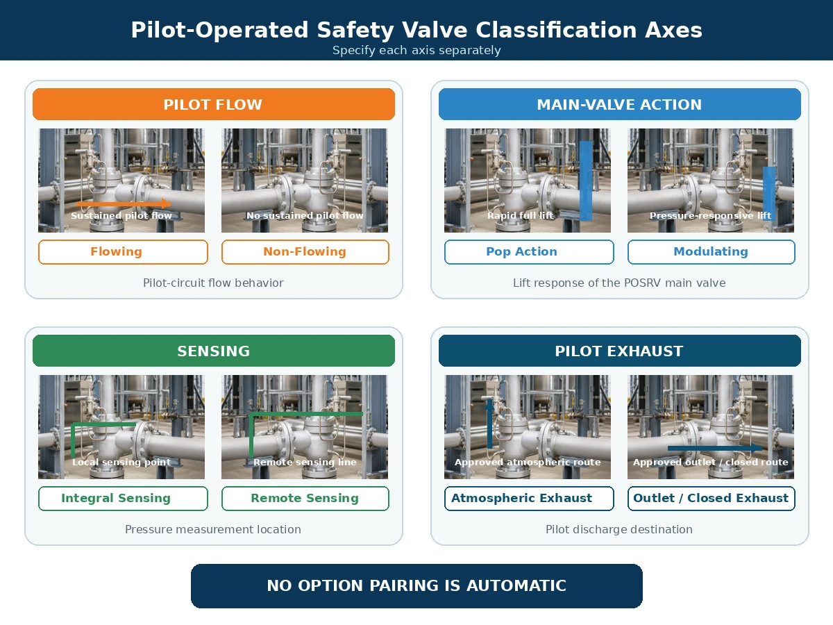
Comparación técnica simplificada. Las combinaciones disponibles dependen del fabricante y la serie de producto seleccionados.
Desplácese horizontalmente para revisar todas las columnas.
| Eje de clasificación | Opciones Típicas | Qué Describe | Lo que no describe |
|---|---|---|---|
| Flujo del piloto | Con flujo / sin flujo | Comportamiento del medio de proceso a través del circuito piloto. | Característica de elevación de la válvula principal. |
| Acción de la válvula principal | Apertura rápida / modulante | Apertura total rápida o elevación proporcional a la presión. | Si el flujo piloto es continuo. |
| Disposición de detección | Integral / remoto | Donde el piloto mide la presión del sistema protegido. | Destino de la descarga del piloto. |
| Disposición de la descarga | Atmósfera / salida / ruta cerrada aprobada | Dónde se descarga el medio del piloto. | Acción de la válvula principal o capacidad de alivio. |
Cómo afectan la descarga del piloto y la contrapresión a la decisión
Descarga a la atmósfera vs. descarga a la salida
La descarga del piloto a la atmósfera puede ser inaceptable para medios tóxicos, inflamables, corrosivos, olorosos, controlados ambientalmente o valiosos. Dirigir la descarga a la salida de la válvula principal puede reducir la liberación local a la atmósfera, pero puede exponer la conexión de descarga del piloto a la contrapresión de salida.
Contrapresión superpuesta y contrapresión acumulada
La contrapresión superpuesta existe antes de que la válvula se abra. La contrapresión acumulada se desarrolla debido al flujo de alivio a través del sistema de salida después de la apertura. Cualquiera de las condiciones puede afectar el equilibrio de fuerzas de la válvula principal, la descarga del piloto, la reducción de presión de la cámara, la elevación, el reasiento y el flujo inverso. Revise estos efectos con la guía de ZOBAI sobre Contrapresión y fuelle.
Desplácese horizontalmente para revisar todas las columnas.
| Condición | Datos requeridos | Pregunta sobre el circuito piloto | Límite de decisión |
|---|---|---|---|
| Contrapresión superpuesta constante | Presión de salida antes de la apertura. | ¿Actúa sobre la descarga, la válvula principal o ambas? | Confirme el límite del modelo y la base de capacidad. |
| Contrapresión superpuesta variable | Perfil de presión de salida mínimo, normal y máximo. | ¿Puede la variación cambiar la apertura, la elevación, la estabilidad o el reasentamiento? | No apruebe basándose en un solo valor promedio. |
| Contrapresión acumulada | Cálculo del sistema de descarga al caudal de alivio gobernante. | ¿Puede restringir la descarga del piloto o reducir el rendimiento de la válvula principal? | Evalúe al caudal requerido, no en operación normal. |
| Descarga del piloto conectada a la salida principal | Presión de salida durante la apertura, el alivio y el reasentamiento. | ¿Cómo se ven afectados el despresurizado de la cámara y el rearme? | Se requiere el esquema de escape aprobado. |
| La presión de salida puede superar la presión de entrada o la de la cámara. | Diferencial inverso creíble y secuencia de operación. | ¿Se requiere prevención de flujo inverso u otro control? | No asuma que el arreglo estándar del piloto evita el flujo inverso. |
Protección contra flujo inverso y del circuito piloto.
Si la presión de salida supera la presión de entrada o la de la cámara, el medio de descarga puede ingresar a la cámara o al circuito piloto, o crear una fuerza de apertura no intencionada en la válvula principal. Los controles específicos del fabricante pueden incluir dispositivos de retención, prevención de flujo inverso y arreglos de escape aprobados.
Riesgos de medio, temperatura y contaminación.
Gas limpio y vapor.
El gas seco limpio reduce algunas preocupaciones de drenaje y ensuciamiento, pero la composición, la temperatura de expansión, los sellos y la clasificación del escape aún requieren revisión.
Condensación, formación de hielo e hidratos.
La humedad, los pasos pequeños y los puntos bajos pueden crear condensación, formación de hielo o hidratos. La operación sin flujo no elimina los requisitos de drenaje y protección invernal.
Medio sucio o solidificante
El óxido, las incrustaciones, las partículas, la cera y los depósitos pueden restringir los componentes del piloto. Los filtros deben ser adecuados, accesibles y mantenidos.
Temperatura y medidas auxiliares
Revise todos los componentes afectados del piloto y de la válvula principal, no solo el material del cuerpo: piezas en contacto con el medio, tobera, disco, guía, tubería, resorte, asiento/sello, diafragma y cualquier fuelle utilizado en la configuración de la válvula principal seleccionada. Puede ser necesario montaje remoto, calefacción, enfriamiento o materiales diferentes.
Desplácese horizontalmente para revisar todas las columnas.
| Medio o condición | Riesgo del sistema piloto | Elementos a confirmar | Cuándo no proceder sin revisión |
|---|---|---|---|
| Gas o vapor seco y limpio | El enfriamiento por expansión, los sellos y el escape peligroso siguen siendo importantes. | Cuerpo del piloto, tubería, asientos, sellos, temperatura mínima y ruta de escape. | Cuando se desconoce la composición, la temperatura de alivio o la clase de escape. |
| Gas húmedo o vapor condensable | Condensado, formación de hielo, hidratos y vías de detección obstruidas. | Trazado con autodrenaje, puntos bajos, drenajes, calefacción y ubicación del filtro. | Cuando las líneas de detección y de escape no se pueden drenar ni proteger contra el invierno. |
| Medio sucio o con partículas | Restricciones obstruidas, asientos dañados, filtros tapados y contaminación de la cámara. | Características de las partículas, filtración, tamaño de paso y acceso para mantenimiento. | Cuando no se documenta la idoneidad o una estrategia de protección mantenible. |
| Medio corrosivo | Ataque al cuerpo del piloto, tubería, partes internas húmedas, asientos y sellos blandos. | Materiales, tubería, compatibilidad de asientos/sellos y registros. | Cuando la revisión se basa solo en el material del cuerpo de la válvula principal. |
| Servicio de polimerización, cristalización o solidificación | Atascamiento, pasajes bloqueados, depósitos y control de cámara deteriorado. | Control de temperatura, purga/enjuague, tramos muertos y base de mantenimiento. | Cuando pueden formarse depósitos en pasajes inaccesibles. |
| Servicio de alta o baja temperatura | El resorte piloto, los asientos, los sellos, el diafragma, los tubos y los filtros pueden experimentar temperaturas diferentes a las del cuerpo principal. | Temperaturas de operación y de alivio, extremos ambientales, montaje remoto, disposiciones de calefacción o enfriamiento. | Cuando solo se ha verificado la clasificación de temperatura del cuerpo de la válvula principal. |
| Servicio de líquido, con destello o bifásico | La respuesta dinámica, la base de capacidad y la estabilidad del piloto pueden diferir del servicio de gas. | Base de fase exacta, condiciones de alivio y aprobación explícita del fabricante. | Cuando la fase se asume en lugar de calcularse o confirmarse. |
Controles de instalación: qué hacer y qué evitar
La arquitectura del piloto solo puede funcionar como se pretende cuando la entrada, la salida, la línea de detección, el tubo del domo y el escape del piloto de la válvula principal se instalan como un sistema integrado de protección contra presión. Para controles detallados de entrada, salida, soporte y línea de detección, use la guía de instalación de válvulas de seguridad.
Hacer
- Mantenga la entrada de la válvula principal corta y directa, y evalúe la pérdida de presión de entrada para el caso de alivio gobernante.
- Apoye la tubería de salida de forma independiente y revise la fuerza de reacción de descarga, el movimiento térmico y las cargas en el colector.
- Tienda las líneas de detección remotas para minimizar la pérdida de presión, la pulsación, los bolsillos de líquido y el aislamiento accidental.
- Soporte el tubo piloto y conserve el diámetro interno, los accesorios y los puntos de conexión requeridos por el fabricante.
- Dirija la descarga del piloto a un destino seguro aprobado y evalúe la presión impuesta en esa ruta.
- Proporcione drenaje, calefacción, aislamiento o protección ambiental cuando el servicio y las instrucciones del fabricante lo requieran.
- Mantenga accesibles las ventilaciones, drenajes, filtros, conexiones de prueba y uniones de mantenimiento.
No hacer
- No conecte la línea de detección a un punto arbitrario ni asuma que la presión de salida es la presión del sistema protegido.
- No agregue válvulas de aislamiento a las líneas de detección o piloto sin un arreglo bloqueado o controlado aprobado.
- No reduzca el tamaño del tubo, agregue tramos largos sin soporte ni cree puntos bajos sin revisar el efecto de respuesta.
- No bloquee, tape ni combine una ventilación o drenaje del piloto a menos que el diseño seleccionado lo permita explícitamente.
- No permita que la válvula principal soporte el peso o la carga de reacción de la tubería de descarga pesada.
- No trate el trazado térmico, el purgado o los filtros como remedios universales para un medio inadecuado.
- No cambie el recorrido de escape sin verificar la contrapresión, la zona peligrosa y los requisitos ambientales.
Modos de fallo comunes y comprobaciones de mantenimiento
Desplácese horizontalmente para revisar todas las columnas.
| Síntoma observado | Posible causa en el circuito piloto | Otra causa posible | Verificación Requerida |
|---|---|---|---|
| La válvula principal abre tarde | Línea de detección o entrada del piloto bloqueada. | Medición de presión incorrecta o problema de presión de ajuste. | Verifique la ruta de detección y los datos de prueba calibrados. |
| La válvula principal abre temprano | Fuga en el asiento del piloto o ajuste incorrecto del piloto. | Pulsación de presión o punto de detección inadecuado. | Inspeccione el piloto y la fuente de presión. |
| La válvula principal no alcanza la elevación esperada | Salida del piloto restringida o despresurización inadecuada del domo. | Flujo de proceso insuficiente o contrapresión excesiva. | Revise la salida del piloto y el sistema instalado. |
| La válvula principal cicla | Inestabilidad del piloto o pulsación en la línea de sensado. | Sobredimensionamiento, pérdida en la entrada o contrapresión variable. | Revise el sistema de alivio completo. |
| Reasiento lento | Vía de recarga del domo restringida. | Fricción en la válvula principal o blowdown inadecuado. | Inspeccione el piloto y la válvula principal. |
| El venteo del piloto se congela | Medio húmedo y enfriamiento por expansión. | Exposición ambiental o drenaje deficiente. | Revise el control de humedad y la protección invernal. |
El mantenimiento debe seguir un procedimiento aprobado de aislamiento, despresurización y prueba. No bloquee los venteos o drenajes del piloto, no altere la tubería sin preservar el diseño requerido, ni infiera la capacidad de alivio a partir de una prueba de presión de ajuste.
Flujo de trabajo de decisión para seleccionar la arquitectura del piloto
1. Definir el caso de alivio
- Equipo protegido y escenario de sobrepresión dominante; utilice la Sistemas de alivio de presión API 521 guía cuando la base del proyecto adopte API 521
- Presión de operación, MAWP o presión de diseño y presión de ajuste
- Sobrepresión admisible y acumulación
- Capacidad de alivio requerida y base de cálculo
- Presión de alivio, temperatura de alivio, medio y fase
2. Definir el flujo del piloto y los requisitos de escape
- Si el flujo continuo del piloto es aceptable
- Requisito de escape atmosférico, de salida o cerrado
- Acción de apertura total o modulante
- Detección integral o remota
- Requisitos de prevención de contracorriente y prueba en campo
3. Revisar los riesgos del servicio y de fallo
- Contaminación, corrosión y solidificación
- Condensación, formación de hielo e hidratos
- Vibración, pulsación y disposición de la línea de sensado
- Exposición ambiental y acceso para mantenimiento
4. Confirmar el diseño específico del fabricante
- Esquema de funcionamiento pilotado y hoja de datos del modelo
- Límites de presión, temperatura, fase y contrapresión
- Materiales, sellos, filtros, calentadores y drenajes
- Capacidad documentada y documentos requeridos del proyecto
Cuándo esta comparación no es suficiente
No seleccione una válvula basándose únicamente en la comparación de flujo/no flujo cuando cualquiera de los siguientes puntos permanezca sin resolver:
- El equipo protegido o el escenario de alivio gobernante no ha sido identificado.
- Falta la capacidad de alivio requerida, la presión de alivio, la temperatura de alivio o la base de fase.
- La contrapresión superpuesta o acumulada es variable, desconocida o afectada por un cabezal común.
- El medio puede congelarse, polimerizarse, cristalizarse, corroerse, ensuciarse o transportar sólidos.
- Se requiere detección remota, escape piloto cerrado, prevención de flujo inverso o pruebas de campo.
- El esquema piloto original, el enrutamiento del escape o la fuente de detección de la válvula de reemplazo no están disponibles.
- El fabricante seleccionado no ha confirmado el servicio, los materiales, la acción del piloto y los accesorios.
Escenarios de Ingeniería Compuestos
Los siguientes escenarios son ejemplos de formación compuestos. No representan clientes nombrados, incidentes verificados ni proyectos completados de ZOBAI.
Gas limpio de alta presión con emisiones atmosféricas restringidas
Problema observado: Una RFQ especifica “no flujo requerido” solo porque las emisiones atmosféricas locales están restringidas. Causa técnica: La solicitud trata el flujo piloto estable como si fuera la única vía de descarga posible. Corrección: Compare la descarga transitoria del piloto, el flujo piloto estable, la descarga de la válvula principal, el enrutamiento de la descarga, la contrapresión y la capacidad documentada. Prevención: Exija el esquema del piloto seleccionado y un destino de descarga aprobado antes de la aprobación del modelo.
Gas húmedo con riesgo de condensación y congelación
Problema observado: Un piloto de gas húmedo responde lentamente o se vuelve inestable durante baja temperatura ambiente. Causa técnica: La humedad se acumula en los puntos bajos de detección o de descarga y se congela durante la reducción de presión. Corrección: Restablezca el enrutamiento autodrenante y aplique el drenaje, calentamiento o disposición de invernaje aprobado por el fabricante. Prevención: Confirmar la temperatura mínima, la condición de humedad, el trazado de la línea, los filtros y el acceso de mantenimiento durante la revisión del diseño.
Válvula de reemplazo con ruta de escape del piloto no confirmada
Problema observado: Una POSRV de reemplazo coincide con los tamaños de brida y la presión de ajuste, pero no reproduce el comportamiento operativo original. Causa técnica: No se verificó el tipo de piloto original, la fuente de detección, la ruta de escape, la base de capacidad o la condición de contrapresión. Corrección: Reconstruir la base de alivio y comparar el esquema operativo completo y la capacidad documentada. Prevención: Controlar los reemplazos mediante gestión del cambio, dibujos aprobados, registros de pruebas, datos de placa de identificación y trazabilidad.
Flujo de trabajo de verificación de reemplazo
Una válvula de seguridad pilotada no debe reemplazarse solo por coincidir en apariencia, tamaño de entrada, tamaño de salida y presión de ajuste.
Qué deben incluir los compradores en la hoja de datos y la RFQ
Especificar solo “válvula de seguridad pilotada”, el tamaño de entrada y la presión de ajuste no es suficiente. El proveedor necesita requisitos completos de proceso, alivio, circuito piloto y documentación.
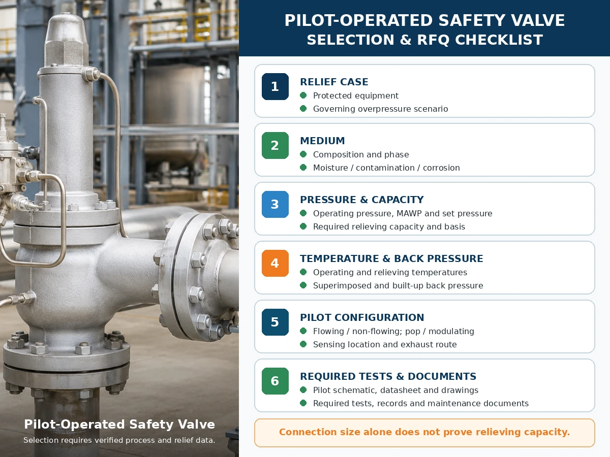
Solo lista de verificación de ingeniería. La selección final del modelo depende de datos de proceso verificados, información del fabricante, normas aplicables y revisión del proyecto.
Desplácese horizontalmente para revisar todas las columnas.
| Entrada requerida | Por qué es importante | Estado |
|---|---|---|
| Equipo protegido y escenario de alivio principal | Define el deber de protección de presión y la carga requerida. | Por confirmar |
| Medio, composición y fase | Afecta al piloto, los sellos, el manejo del escape y la base de capacidad. | Por confirmar |
| Presión de operación, MAWP/presión de diseño y presión de tarado | Define el margen de operación y el límite de presión. | Por confirmar |
| Sobrepresión admisible y acumulación | Afecta el dimensionamiento y la base de alivio aplicable. | Por confirmar |
| Capacidad de alivio requerida y base de cálculo | Determina la capacidad documentada requerida de la válvula. | Por confirmar |
| Temperaturas de operación y de alivio | Controla los materiales, los sellos, la disposición del piloto y la base de capacidad. | Por confirmar |
| Contrapresión superpuesta y acumulada | Afecta el comportamiento de la válvula principal y del escape del piloto. | Por confirmar |
| Con flujo/sin flujo, pop/modulante, detección y escape | Define cuatro decisiones independientes del sistema piloto. | Por confirmar |
| Materiales, filtrado, calefacción, drenaje y acceso para mantenimiento | Aborda la compatibilidad del servicio y los controles de fallos. | Por confirmar |
| Código aplicable, pruebas y documentos | Define el paquete de evidencia del proyecto. | Por confirmar |
Matriz de pruebas y documentación
Las pruebas y la documentación deben mostrar diferentes partes de la cadena de evidencia de protección contra presión. Un informe de prueba no debe utilizarse para reclamar resultados que no establece.
Desplácese horizontalmente para revisar todas las columnas.
| Prueba o Documento | Lo que puede respaldar | Lo que no demuestra por sí solo | Verificación de RFQ |
|---|---|---|---|
| Prueba de presión de ajuste de piloto o válvula ensamblada | Respuesta de presión de apertura bajo el procedimiento indicado. | Capacidad, respuesta de contrapresión en campo o compatibilidad del proceso. | Especificar medio, procedimiento, base de aceptación y formato del informe. |
| Prueba de estanqueidad del asiento / Prueba de estanqueidad de asiento API 527 orientación cuando corresponda | Fuga bajo las condiciones y criterios indicados. | Cero fugas en todos los servicios o condiciones de operación. | Especificar método, presión de prueba, medio y criterios de aceptación. |
| Prueba funcional de piloto/válvula principal | Actuación del piloto, control de domo, movimiento de la válvula principal y rearme. | Capacidad total de campo o rendimiento de la línea de descarga no probada. | Confirmar arquitectura, tipo de acción y accesorios incluidos. |
| Tabla de capacidad, certificado o registro de cálculo | Rendimiento de alivio documentado para el diseño seleccionado. | Idoneidad para una fase, temperatura, contrapresión o medio diferente. | Coincidir modelo, orificio, base de fluido y evidencia requerida. |
| Disposición general y esquema de operación del piloto | Conexiones, rutas de flujo, detección, escape y accesorios. | Compatibilidad de materiales o capacidad, salvo que se documente por separado. | Solicitar la revisión del plano utilizada para la fabricación e instalación. |
| Registros de materiales | Identidad de material especificada para los componentes que soportan presión y los componentes humedecidos enumerados. | Idoneidad frente a la corrosión sin una revisión de materiales específica del servicio. | Definir qué componentes y nivel de trazabilidad se requieren. |
| Hoja de datos, placa de identificación y liberación de inspección. | Configuración, presión de ajuste, identificación del modelo y estado de inspección acordado. | Un cálculo de alivio completo o una certificación universal. | Verificar la coherencia entre la orden de compra, el plano, los informes de prueba y la placa de identificación final. |
| Instrucciones de instalación y mantenimiento | Orientación aprobada sobre tuberías, detección, escape, pruebas, mantenimiento y repuestos. | Aprobación del proyecto cuando la disposición instalada difiera de las instrucciones. | Incluir la revisión exacta de la serie de producto en el paquete de documentación. |
Normas y notas de referencia
La evidencia operativa específica del fabricante se enlaza junto a las declaraciones relevantes de flujo, no flujo y apertura/modulación anteriores. Esos documentos solo respaldan a las familias de productos identificadas y no deben tratarse como datos universales de rendimiento de válvulas POSRV.
- API 520 Parte I, 10ª Edición — aviso oficial de la publicación de dimensionamiento y selección de API.
- API 520 Parte II, 7ª Edición — aviso oficial de la publicación de instalación de API.
- ASME BPVC Sección XIII, Edición 2025 — reglas para la protección contra sobrepresión.
- ISO 4126-4:2013 — válvulas de seguridad pilotadas; ISO enumera la publicación como revisada y confirmada en 2025.
Estas referencias tienen diferentes alcances. Confirme la edición adoptada por el proyecto, el código del equipo protegido, la jurisdicción, el alcance del fabricante/modelo y la documentación requerida. El nombre de una norma no es prueba de que cada modelo de ZOBAI tenga todas las certificaciones.
Preguntas Frecuentes
¿Cuál es la diferencia entre una válvula de seguridad pilotada de flujo y una de no flujo?
Un piloto de flujo continuo mantiene un recorrido de piloto diseñado durante el estado de alivio estable correspondiente. Un piloto sin flujo continuo detiene el flujo continuo del piloto en una condición estable de la válvula principal, aunque puede producirse un flujo transitorio durante la actuación y la recarga de la cámara.
¿Un piloto sin flujo significa que el medio de proceso nunca pasa a través del piloto?
N.º El medio puede pasar mientras el piloto actúa, cambia la presión de la cúpula o represuriza la cúpula. No fluyente se refiere a la condición estable, no a cada instante.
¿Es un piloto sin flujo siempre mejor que un piloto con flujo?
N.º La idoneidad depende del medio, la ruta de escape, la temperatura, la contaminación, la contrapresión, la capacidad requerida, el tipo de acción y el diseño del fabricante seleccionado.
¿Es lo mismo flujo continuo que no continuo que acción de apertura total frente a modulante?
N.º El flujo o no flujo describe el flujo del circuito piloto. La apertura total o modulante describe la respuesta de elevación de la válvula principal. Especifíquelos por separado.
¿A dónde va el escape del piloto?
Según el diseño, la descarga del piloto puede ir a la atmósfera, a la salida principal o a otra ruta cerrada aprobada. Confirme el esquema y el efecto de la contrapresión.
¿Qué tipo de piloto es mejor para medios de proceso peligrosos o valiosos?
Un diseño sin flujo continuo puede reducir la pérdida sostenida de medio piloto, pero la descarga transitoria, la descarga principal, los criterios de fuga, el trazado y la idoneidad del modelo aún requieren revisión.
¿Puede un piloto sin flujo experimentar congelación o contaminación?
Sí. Las líneas de detección, filtros, restricciones, pasos del domo y escapes pueden acumular humedad, congelarse u obstruirse. El drenaje, la filtración y la preparación para invierno siguen siendo específicos del servicio.
¿Qué información se requiere antes de seleccionar la arquitectura pilotada?
Proporcione el equipo protegido, el escenario de alivio, el medio y la fase, los datos de presión, la capacidad requerida, la temperatura de alivio, la contrapresión, la detección, la descarga, la tubería, los materiales, el tipo de acción y los documentos requeridos.
Normas y limitaciones de ingeniería
La API 520 Parte I aborda el dimensionamiento y la selección, mientras que la API 520 Parte II aborda la instalación dentro de sus alcances declarados. La ASME BPVC Sección XIII proporciona un marco de protección contra sobrepresión. La ISO 4126-4 aborda las válvulas de seguridad pilotadas como norma de producto; no es un código de aplicación para el sistema protegido. Verifique la edición adoptada por el proyecto, el código de equipo aplicable, la jurisdicción y los datos específicos del producto del fabricante.
La selección final depende del equipo protegido, el escenario de alivio gobernante, el medio y la fase reales, la presión de operación, la MAWP o presión de diseño, la presión de ajuste, la capacidad de alivio requerida y documentada, la temperatura de alivio, la contrapresión superpuesta y acumulada, las tuberías de entrada y salida, todos los materiales y componentes de sellado afectados, la configuración del piloto, la edición de la norma adoptada, la especificación del proyecto y los requisitos reglamentarios locales aplicables.
Solicitar revisión de ingeniería de válvula de seguridad pilotada
La elección final entre válvulas de seguridad pilotadas de flujo continuo y de flujo no continuo debe basarse en el escenario real de alivio, la capacidad requerida, el medio y su fase, la temperatura de alivio, la contrapresión, la disposición de sensado y escape, los materiales, la tubería y la documentación requerida. Envíe estos datos antes de solicitar una recomendación de modelo.