Confronto tecnico tra valvole di sicurezza pilotate flussanti e non flussanti

Confronto tecnico tra valvole di sicurezza pilotate
Le valvole di sicurezza pilotate flussanti e non flussanti differiscono principalmente nel circuito pilota durante lo scarico stabile. Un design flussante mantiene normalmente una soffiatura o un flusso controllato; un design non flussante normalmente interrompe il flusso pilota continuo dopo che la valvola principale raggiunge una condizione di scarico stabile, sebbene possa verificarsi ancora un flusso transitorio durante l'attivazione, la regolazione dell'alzata, la richiusura e il ricaricamento del domo. La distinzione è importante quando lo scarico del pilota, le emissioni, l'umidità, la contaminazione, la formazione di ghiaccio, la contropressione o lo scarico di lunga durata influenzano la specifica. Non definisce l'azione pop o modulante, la posizione di rilevamento o la capacità di scarico. Anche la pressione di taratura e la dimensione della connessione non dimostrano che la valvola selezionata abbia una capacità documentata adeguata. Prima della selezione, confermare l'apparecchiatura protetta, lo scenario di scarico, il fluido e la fase, la pressione di esercizio, la MAWP o la pressione di progetto, la pressione di taratura, la capacità richiesta, la temperatura di scarico, la contropressione sovrapposta e accumulata, la sorgente di rilevamento, la destinazione dello scarico, i materiali e i documenti richiesti. Inviare queste condizioni per una revisione tecnica.
Valvole di sicurezza pilotate a flusso continuo e non a flusso continuo: risposta rapida
Il termine 'a flusso continuo' o 'non a flusso continuo' descrive il comportamento del fluido di processo attraverso il circuito pilota. Un pilota a flusso continuo mantiene normalmente un flusso progettato durante lo stato di scarico stabile; un pilota non a flusso continuo interrompe normalmente il flusso continuo del pilota a sollevamento stabile. Nessuno dei due termini definisce l'azione della valvola principale, la posizione di rilevamento, la destinazione dello scarico o la capacità di scarico.
Un pilota non a flusso continuo può comunque far passare un volume transitorio durante l'attivazione, la variazione della pressione nella camera o la ripressurizzazione della camera. Non deve essere descritto come a flusso zero, a zero emissioni o esente da manutenzione.
Valutare l'architettura selezionata nell'ambito dell'intero valvola di sicurezza pilotata sistema, senza considerare la classificazione del flusso del pilota come specifica completa.
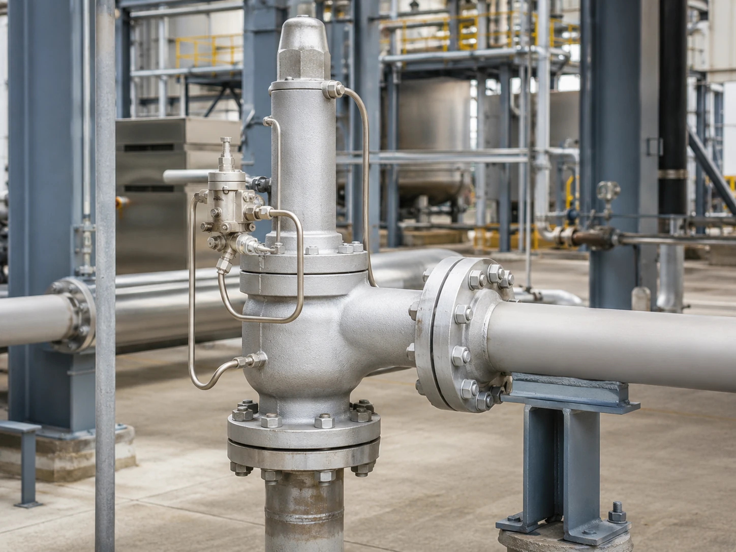
Visualizzazione concettuale realistica. La geometria finale della valvola, il rilevamento, il percorso di scarico, il campo di pressione e la capacità documentata devono essere confermati in base al modello selezionato.
Limite di selezione: Nessun tipo di pilota è universalmente migliore. L'architettura del pilota non determina la capacità richiesta, l'orifizio selezionato, la contropressione ammissibile, la compatibilità dei materiali o l'idoneità al codice. Queste decisioni richiedono lo scenario di scarico applicabile e la documentazione specifica del produttore.
Matrice di selezione preliminare
Questa matrice è uno strumento di screening, non una raccomandazione di modello. Identifica le domande che dovrebbero essere risolte prima di specificare un pilota a flusso continuo o non a flusso continuo.
Scorrere orizzontalmente per visualizzare tutte le colonne.
| Condizione di servizio o di progetto | Perché è Importante | Revisione pilota a flusso continuo | Revisione pilota a flusso non continuo | Punto di controllo tecnico |
|---|---|---|---|---|
| Lo scarico atmosferico locale del pilota è limitato | Lo sfiato del pilota può essere inaccettabile per fluidi pericolosi, preziosi o regolamentati. | Confermare il flusso continuo del pilota e il percorso approvato. | Confermare lo scarico transitorio e la condizione stabile del modello selezionato. | Sospendere la selezione finché non sono definiti la destinazione dello scarico e gli effetti della pressione di uscita. |
| Gli eventi di scarico possono essere prolungati | La lunga durata può aumentare la perdita di fluido del pilota e il carico del sistema di scarico. | Richiedere i dati sul ciclo operativo e sul flusso del pilota. | Confermare quando il flusso continuo si interrompe e come viene controllata l'alzata. | La durata da sola non determina l'architettura; capacità e stabilità restano i fattori principali. |
| Gas umido, bassa temperatura ambiente o rischio di idrati | Restrizioni, filtri, linee di rilevamento e percorsi di scarico possono congelarsi o accumulare liquido. | Valutare il raffreddamento per espansione, il drenaggio, il riscaldamento e i limiti di temperatura. | Valutare l'espansione transitoria, la ricarica della cupola e le linee di rilevamento umide. | Attendere fino a quando il controllo dell'umidità e la temperatura minima non sono confermati. |
| Fluido sporco, polimerizzante o con particolato | Passaggi e sedi di piccole dimensioni possono ostruirsi, aderire o erodersi. | Valutare l'esposizione continua di restrizioni e filtri. | Valutare sedi, percorsi transitori, filtrazione e contaminazione della cupola. | Un filtro da solo non rende il servizio accettabile. |
| Pressione di uscita variabile o collettore di scarico comune | La pressione di scarico può modificare lo scarico del pilota e l'equilibrio delle forze della valvola principale. | Verificare come la pressione di scarico agisce sul circuito di scarico e sulla camera del pilota. | Confermare il controllo stabile dello sfioro, il ripristino e il comportamento del riflusso. | Separare la contropressione sovrapposta da quella accumulata. |
| È richiesto il rilevamento remoto | Il percorso della linea di rilevamento, la perdita di pressione, la pulsazione, lo scarico e l'isolamento possono influenzare il funzionamento. | Confermare che il segnale remoto sia compatibile con il circuito pilota selezionato. | Confermare il controllo della camera superiore e la risposta transitoria con la disposizione di rilevamento remoto. | Non dedurre l'idoneità del rilevamento remoto dalla classificazione del flusso pilota. |
| Il servizio con liquido, lampeggiamento o bifase è possibile | Il comportamento delle fasi influisce sulla capacità, sulla dinamica del pilota e sulla stabilità dello scarico. | Richiedere l'approvazione esplicita del produttore per la fase effettiva e il caso di sfioro. | Richiedere l'approvazione esplicita del produttore per la fase effettiva e il caso di sfioro. | Il confronto tra flusso e non flusso da solo non è sufficiente. |
Punto di blocco RFQ: Non convertire una preferenza come “flusso non richiesto” in una selezione definitiva del modello finché non sono disponibili il carico di scarico, la fase, la temperatura di scarico, la contropressione, la sorgente di rilevamento e la destinazione dello scarico.
Come una valvola di sicurezza pilotata controlla la valvola principale
Valvola principale, pilota e pressione della camera
Un sistema tipico include la valvola di scarico principale, il pilota, la camera o la camera di controllo, il percorso di rilevamento, i tubi e lo scarico del pilota. Al di sotto della pressione di taratura, la pressione di processo mantiene normalmente la pressione della camera e la forza di chiusura della valvola principale.
Alla pressione di taratura, il pilota modifica il percorso della pressione della camera in modo che la pressione di ingresso possa aprire la valvola principale. Quando la pressione scende verso la pressione di chiusura del pilota, la camera viene ripressurizzata e la valvola principale si richiude.
Pressione di rilevamento e scarico del pilota
La pressione può essere rilevata in modo integrale o remoto. Lo scarico del pilota può andare all'atmosfera, all'uscita principale o a un altro percorso chiuso approvato; nessuna delle due scelte è determinata dalla classificazione di flusso o non flusso.
Il funzionamento del pilota non sostituisce la verifica della capacità
La risposta alla pressione di taratura non dimostra che la valvola possa far passare il carico di scarico di governo. Confermare separatamente la capacità richiesta, l'orifizio selezionato e la capacità documentata; la dimensione della connessione non è una base per la capacità. Vedere dimensionamento della valvola di sicurezza e alla capacità di sfioro certificata.
Capacità richiesta, valvola selezionata e prove sono diverse
L'architettura del pilota controlla la valvola principale, ma non sostituisce la catena di selezione della capacità. Ogni elemento di seguito risponde a una diversa domanda ingegneristica.
I valori di capacità per vapore, aria o gas, liquido e bifase non sono intercambiabili. La base di capacità selezionata deve corrispondere al mezzo di scarico effettivo, alla fase, alla pressione, alla temperatura, alla contropressione e al metodo di calcolo applicabile.
Scorrere orizzontalmente per visualizzare tutte le colonne.
| Articolo | Cosa rappresenta | Evidenza richiesta | Cosa non prova |
|---|---|---|---|
| Capacità di sfioro richiesta | Carico di scarico dallo scenario di sovrappressione dominante. | Base di calcolo, proprietà del fluido, fase, pressione e temperatura di scarico. | Non seleziona la dimensione della connessione né il tipo di pilota. |
| Area di flusso richiesta | Area effettiva minima calcolata per la base di dimensionamento. | Metodo applicabile, coefficienti, contropressione e ipotesi sul fluido. | Non dimostra che un orifizio commerciale abbia una capacità documentata sufficiente. |
| Orifizio o progetto di valvola selezionato | Geometria del produttore scelta per soddisfare il carico richiesto. | Scheda tecnica del modello, designazione dell'orifizio e documentazione della capacità. | Non dimostra l'idoneità di temperatura, materiale, scarico o contropressione. |
| Capacità documentata o certificata | Prestazioni pubblicate o documentate nelle condizioni dichiarate. | Tabella di capacità, certificato o registro di calcolo richiesti dal progetto. | Non sostituisce la verifica del fluido effettivo e delle condizioni di scarico. |
| Dimensione connessione ingresso e uscita | L'interfaccia della tubazione e la connessione flangiata o filettata. | Disposizione generale e specifica di connessione. | La sola dimensione della connessione non dimostra la capacità di scarico. |
| Collaudo pressione di taratura | La risposta di pressione del pilota e della valvola durante la procedura di prova. | Registro di prova calibrato e criteri di accettazione applicabili. | Non dimostra in modo indipendente la capacità in campo, l'idoneità di fase o le prestazioni in contropressione. |
Nota di revisione tecnica: Una richiesta contenente solo la pressione di taratura e la dimensione della connessione è incompleta. La capacità di scarico richiesta e la sua base di calcolo sono input separati e devono essere trattati come punti di blocco obbligatori prima della conferma del modello.
I Quattro Stati Operativi che gli Acquirenti Dovrebbero Confrontare
Scorrere orizzontalmente per visualizzare tutte le colonne.
| Stato Operativo | Revisione pilota a flusso continuo | Revisione pilota a flusso non continuo | Verifica Specifica del Modello |
|---|---|---|---|
| Funzionamento normale in chiuso | Verificare se esiste un percorso di spurgo o circolazione progettato. | Determinare se il circuito pilota diventa statico dopo la pressurizzazione della camera. | Disposizione di alimentazione, camera e sede di scarico. |
| Attuazione del pilota | Identificare come cambia il percorso del flusso pilota. | Identificare il volume transitorio che passa attraverso il pilota. | Sequenza di attuazione e percorso di depressurizzazione della camera. |
| Sfioro stabile della valvola principale | Confermare se il flusso pilota continua. | Confermare che il flusso pilota continuo si interrompe all'alzata stabile. | Schema operativo del produttore. |
| Richiusura e ripressurizzazione della camera | Confermare come viene ricostruita la pressione della camera. | Confermare il flusso di ricarica transitorio e il riarmo del pilota. | Pressione di chiusura, risposta di blowdown e contropressione. |
Stato 1: Funzionamento normale chiuso
Al di sotto della pressione di taratura, verificare la condizione della sede del pilota, lo scarico della linea di rilevamento, la condizione del filtro e l'eventuale perdita dalla cupola.
Stato 2: Attuazione del pilota
Alla pressione di taratura, il pilota limita l'alimentazione alla cupola e ne riduce la pressione. Durante questa transizione si verifica normalmente un certo flusso pilota, anche in un design non a flusso continuo.
Stato 3: Scarico stabile della valvola principale
Questo stato separa le classificazioni: i design a flusso continuo mantengono il percorso pilota previsto, mentre i design non a flusso continuo interrompono il flusso pilota continuo a sollevamento stabile.
Stato 4: Richiusura e ripressurizzazione della cupola
Quando la pressione diminuisce, il pilota ripristina la pressione della cupola. Un pilota non a flusso continuo può ancora far passare un flusso di ricarica transitorio prima che la valvola principale si chiuda.
Cos'è un pilota a flusso continuo?
Un pilota a flusso continuo mantiene un percorso del fluido di processo progettato durante lo stato di scarico stabile pertinente. Il flusso è piccolo rispetto allo scarico principale, ma può essere importante per fluidi tossici, infiammabili, corrosivi, preziosi o contenenti umidità. Fondamentali operativi di Baker Hughes descrivono i piloti a flusso e a non flusso come un asse di classificazione.
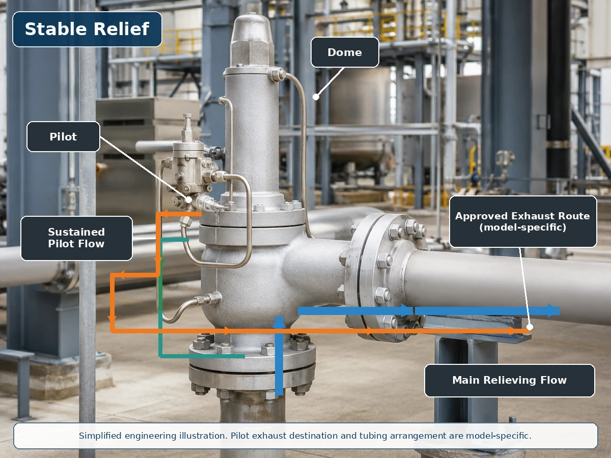
Illustrazione tecnica semplificata basata su un'installazione reale della valvola. I percorsi effettivi di alimentazione del pilota, del serbatoio e di scarico sono specifici del modello.
Percorso del flusso durante lo scarico della valvola principale
Durante lo scarico, il flusso continuo del pilota può sfogare o regolare la pressione del serbatoio. Confermare la base del flusso del pilota, la destinazione dello scarico e le conseguenze sul servizio, piuttosto che considerare il flusso come un'esclusione automatica.
Scarico del pilota e ripressurizzazione del serbatoio
Verificare se lo scarico va in atmosfera, all'uscita o a un altro sistema approvato, e se la pressione di uscita, la condensa, il drenaggio, il riscaldamento o la protezione invernale lo influenzano.
Cos'è un pilota a non flusso?
Un pilota a non flusso raggiunge una condizione stabile in cui il flusso continuo del fluido di processo attraverso il pilota si interrompe mentre la valvola principale può rimanere aperta. I sedili interni, gli elementi di feedback e i dettagli di controllo del serbatoio rimangono specifici del modello. Manuale della serie 800 di Emerson descrive questa condizione di scarico stabile e nota anche il flusso transitorio quando il pilota cambia alzata.

Illustrazione tecnica semplificata. Flusso non continuo non significa zero flusso transitorio, zero perdite o zero emissioni.
Attivazione transitoria e depressurizzazione della camera
Alla pressione di taratura, la pilota riduce la pressione della camera; una piccola quantità di fluido della camera o di processo può passare durante questa transizione.
Scarico stabile senza flusso continuo della pilota
Ad alzata stabile, la pilota può isolare l'alimentazione e lo scarico, interrompendo il flusso continuo della pilota. Ciò può ridurre il consumo di fluido sostenuto, ma non dimostra zero perdite né elimina i rischi di contaminazione e congelamento.
Reset e ricarica della camera
Quando la pressione diminuisce, il percorso di alimentazione della camera si riapre e si verifica un flusso di ricarica transitorio prima che la valvola principale si chiuda.
Confronto tra pilota a flusso continuo e non continuo
Scorrere orizzontalmente per visualizzare tutte le colonne.
| Fattore tecnico | Pilota a flusso continuo | Pilota a flusso non continuo | Domanda di selezione |
|---|---|---|---|
| Flusso pilota stabile durante lo sfioro | Normalmente mantenuto durante la fase di controllo pertinente. | Normalmente assente a sollevamento stabile della valvola principale. | Cosa mostra lo schema operativo selezionato? |
| Flusso pilota transitorio | Presente. | Presente durante il movimento del pilota o il controllo della camera. | Quali volume e percorso di scarico si applicano? |
| Perdita del fluido di processo | Può essere maggiore attraverso il pilota durante lo sfioro prolungato. | Di solito inferiore attraverso il pilota a sfioro stabile. | Il fluido è pericoloso, prezioso o controllato? |
| Emissioni atmosferiche | Possibile se lo scarico del pilota è aperto all'atmosfera. | Ancora possibile durante l'attivazione se sfogata apertamente. | Dove termina lo scarico del pilota? |
| Esposizione a contaminanti | Dipende dal percorso continuo, dalle restrizioni e dalla filtrazione. | Dipende dalle sedi, dai passaggi, dal flusso transitorio e dalla filtrazione. | Il fluido di processo è adatto al pilota selezionato? |
| Congelamento e formazione di ghiaccio | L'espansione continua può essere rilevante. | L'espansione transitoria e le linee di rilevamento umide possono ancora congelare. | Quali condizioni di temperatura minima e umidità si applicano? |
| Esposizione alla contropressione | Il percorso di scarico può influenzare il controllo del pilota. | Il percorso di scarico può influenzare anche il controllo del pilota. | Lo scarico del pilota è collegato all'uscita? |
| Azione a scatto o modulante | Classificazione separata. | Classificazione separata. | Quale azione della valvola principale è richiesta? |
| Capacità di sfioro | Non determinato dal tipo di flusso del pilota. | Non determinato dal tipo di flusso del pilota. | La capacità documentata è adeguata per il caso di scarico? |
Flusso vs Non-Flusso Non Equivale a Scatto vs Modulante
Il flusso del pilota, l'azione della valvola principale, la posizione di rilevamento e la destinazione dello scarico del pilota sono decisioni indipendenti. Un pilota a flusso non è automaticamente a scatto, e un pilota a non-flusso non è automaticamente modulante. Specifica 2900-40 di Baker Hughes fornisce esempi specifici di prodotto sia di piloti a non-flusso con azione a scatto che di piloti a non-flusso modulanti; Panoramica POSV di LESER spiega separatamente il comportamento di alzata a scatto e modulante.
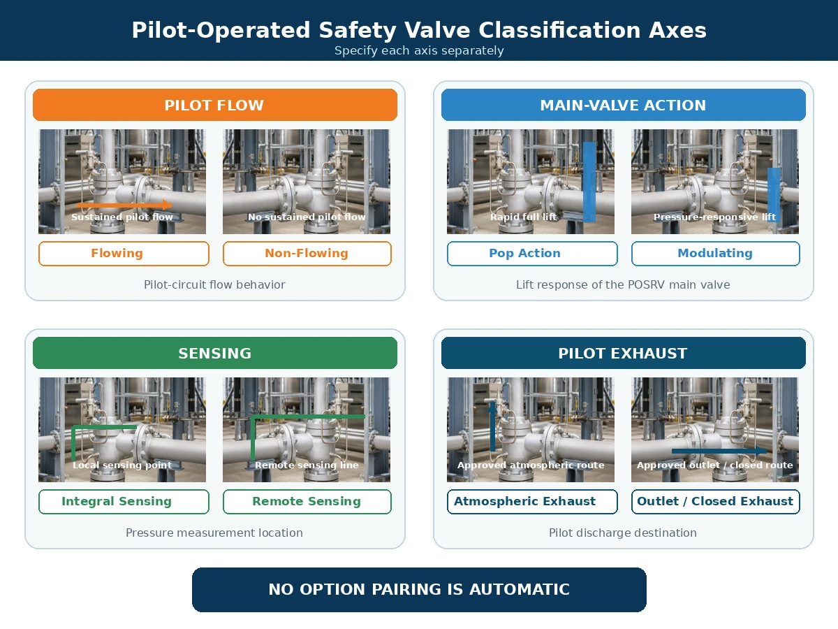
Confronto ingegneristico semplificato. Le combinazioni disponibili dipendono dal produttore e dalla serie di prodotto selezionati.
Scorrere orizzontalmente per visualizzare tutte le colonne.
| Asse di classificazione | Opzioni Tipiche | Cosa descrive | Cosa non descrive |
|---|---|---|---|
| Flusso del pilota | Con flusso / senza flusso | Comportamento del fluido di processo attraverso il circuito del pilota. | Caratteristica di alzata della valvola principale. |
| Azione della valvola principale | A scatto / modulante | Apertura totale rapida o alzata proporzionale alla pressione. | Se il flusso pilota è continuo. |
| Disposizione di rilevamento | Integrale / remota | Dove il pilota misura la pressione del sistema protetto. | Destinazione dello scarico del pilota. |
| Disposizione dello scarico | Atmosfera / uscita / percorso chiuso approvato | Dove viene scaricato il fluido del pilota. | Azione della valvola principale o capacità di scarico. |
Come lo scarico del pilota e la contropressione influenzano la decisione
Scarico in atmosfera vs. scarico in uscita
Lo scarico del pilota in atmosfera può essere inaccettabile per fluidi tossici, infiammabili, corrosivi, maleodoranti, controllati ambientalmente o di valore. Convogliare lo scarico all'uscita della valvola principale può ridurre il rilascio locale in atmosfera, ma può esporre il collegamento di scarico del pilota alla contropressione.
Contropressione sovrapposta e contropressione indotta
La contropressione sovrapposta esiste prima dell'apertura della valvola. La contropressione accumulata si sviluppa a causa del flusso di scarico attraverso il sistema di uscita dopo l'apertura. Entrambe le condizioni possono influenzare l'equilibrio delle forze della valvola principale, lo scarico del pilota, la riduzione della pressione nella camera superiore, l'alzata, la richiusura e il riflusso. Rivedere questi effetti con la guida ZOBAI su Contropressione e soffietto.
Scorrere orizzontalmente per visualizzare tutte le colonne.
| Condizione | Dati richiesti | Domanda sul circuito pilota | Limite di decisione |
|---|---|---|---|
| Contropressione sovrapposta costante | Pressione di uscita prima dell'apertura. | Agisce sullo scarico, sulla valvola principale o su entrambi? | Confermare il limite del modello e la base della capacità. |
| Sovrapposizione di contropressione variabile | Profilo di pressione di uscita minimo, normale e massimo. | La variazione può modificare l'apertura, l'alzata, la stabilità o la richiusura? | Non approvare basandosi su un singolo valore medio. |
| Contropressione accumulata | Calcolo del sistema di scarico alla portata di scarico governante. | Può limitare lo scarico del pilota o ridurre le prestazioni della valvola principale? | Valutare alla portata richiesta, non in condizioni operative normali. |
| Scarico del pilota collegato all'uscita principale | Pressione di uscita durante l'apertura, lo scarico e la richiusura. | Come vengono influenzate la depressurizzazione del domo e il ripristino? | Richiedere lo schema di scarico approvato. |
| La pressione di uscita può superare la pressione di ingresso o quella del domo. | Differenziale inverso credibile e sequenza operativa. | È necessaria la prevenzione del riflusso o un altro controllo? | Non dare per scontato che la disposizione standard del pilota impedisca il flusso inverso. |
Riflusso e protezione del circuito pilota
Se la pressione di uscita supera la pressione di ingresso o quella del domo, il fluido di scarico può entrare nel domo o nel circuito pilota o creare una forza di apertura non intenzionale della valvola principale. I controlli specifici del produttore possono includere dispositivi di non ritorno, prevenzione del riflusso e disposizioni di scarico approvate.
Rischi relativi a fluido, temperatura e contaminazione
Gas e vapore puliti
Il gas secco pulito riduce alcuni problemi di drenaggio e incrostazione, ma composizione, temperatura di espansione, tenute e classificazione dello scarico richiedono comunque una verifica.
Condensa, formazione di ghiaccio e idrati
Umidità, passaggi piccoli e punti bassi possono creare condensa, ghiaccio o idrati. Il funzionamento senza flusso non elimina i requisiti di drenaggio e protezione invernale.
Mezzi sporchi o solidificanti
Ruggine, incrostazioni, particelle, cera e depositi possono ostruire i componenti del pilota. I filtri devono essere adeguati, accessibili e mantenuti.
Temperatura e misure ausiliarie
Esaminare tutti i componenti interessati del pilota e della valvola principale, non solo il materiale del corpo: parti bagnate, ugello, disco, guida, tubazioni, molla, sede/tenuta, membrana ed eventuale soffietto utilizzato nella configurazione della valvola principale selezionata. Potrebbero essere necessari montaggio remoto, riscaldamento, raffreddamento o materiali diversi.
Scorrere orizzontalmente per visualizzare tutte le colonne.
| Mezzo o condizione | Rischio del sistema pilota | Elementi da confermare | Quando non procedere senza revisione |
|---|---|---|---|
| Gas o vapore pulito e secco | Il raffreddamento per espansione, le tenute e lo scarico pericoloso contano comunque. | Corpo del pilota, tubazioni, sedi, tenute, temperatura minima e percorso di scarico. | Quando la composizione, la temperatura di scarico o la classe di scarico non sono note. |
| Gas umido o vapore condensabile | Condensa, ghiaccio, idrati e percorsi di rilevamento bloccati. | Percorso autodrenante, punti bassi, scarichi, riscaldamento e posizione del filtro. | Quando le linee di rilevamento e di scarico non possono essere drenate o protette dal gelo. |
| Fluido sporco o contenente particelle. | Restrizioni bloccate, sedi danneggiate, filtri intasati e contaminazione della camera. | Caratteristiche delle particelle, filtrazione, dimensione del passaggio e accesso per la manutenzione. | Quando l'idoneità o una strategia di protezione manutenibile non è documentata. |
| Mezzo corrosivo | Attacco del corpo del pilota, tubazioni, parti interne a contatto con il fluido, sedi e guarnizioni morbide. | Materiali, tubazioni, compatibilità di sedi/guarnizioni e registrazioni. | Quando la valutazione si basa solo sul materiale del corpo della valvola principale. |
| Servizio con fluidi polimerizzanti, cristallizzanti o solidificanti. | Aderenza, passaggi bloccati, depositi e controllo della camera compromesso. | Controllo della temperatura, spurgo/lavaggio, tratti morti e criteri di manutenzione. | Quando possono formarsi depositi in passaggi inaccessibili. |
| Servizio ad alta o bassa temperatura | La molla del pilota, le sedi, le guarnizioni, il diaframma, i tubi e i filtri possono essere soggetti a temperature diverse da quelle del corpo principale. | Temperature di esercizio e di scarico, estremi ambientali, montaggio remoto, disposizioni di riscaldamento o raffreddamento. | Quando è stata verificata solo la temperatura nominale del corpo della valvola principale. |
| Servizio con liquido, con flash o bifase | La risposta dinamica, la base di capacità e la stabilità del pilota possono differire dal servizio con gas. | Base di fase esatta, condizioni di scarico e approvazione esplicita del produttore. | Quando la fase è presunta piuttosto che calcolata o confermata. |
Controlli di installazione: cosa fare e cosa evitare
L'architettura del pilota può funzionare come previsto solo quando l'ingresso, l'uscita, la linea di rilevamento, i tubi della cupola e lo scarico del pilota della valvola principale sono installati come sistema integrato di protezione dalla pressione. Per controlli dettagliati su ingresso, uscita, supporto e linea di rilevamento, utilizzare il guida all'installazione delle valvole di sicurezza.
Fare
- Mantenere l'ingresso della valvola principale corto e diretto e valutare la perdita di carico in ingresso per il caso di scarico governante.
- Supportare la tubazione di uscita in modo indipendente e verificare la forza di reazione allo scarico, il movimento termico e i carichi sul collettore.
- Instradare le linee di rilevamento remote per ridurre al minimo la perdita di carico, la pulsazione, i sacchetti di liquido e l'isolamento accidentale.
- Supportare i tubi pilota e preservare il diametro interno, i raccordi e i punti di connessione richiesti dal produttore.
- Instradare lo scarico del pilota verso una destinazione sicura approvata e valutare la pressione imposta su quel percorso.
- Fornire drenaggio, riscaldamento, isolamento o protezione ambientale dove il servizio e le istruzioni del produttore lo richiedono.
- Mantenere accessibili sfiato, scarichi, filtri, attacchi di prova e giunti di manutenzione.
Non fare
- Non collegare la linea di rilevamento a un punto arbitrario né assumere che la pressione di uscita sia la pressione del sistema protetto.
- Non aggiungere valvole di isolamento alle linee di rilevamento o pilota senza una disposizione approvata con blocco o controllo.
- Non ridurre il diametro dei tubi, aggiungere lunghi tratti non supportati o creare punti bassi senza valutare l'effetto sulla risposta.
- Non bloccare, tappare o combinare uno sfiato o uno scarico del pilota a meno che il progetto selezionato non lo consenta esplicitamente.
- Non far sopportare alla valvola principale il peso o il carico di reazione di una tubazione di scarico pesante.
- Non trattare il tracciamento termico, lo spurgo o i filtri come rimedi universali per un fluido di processo non idoneo.
- Non modificare il percorso di scarico senza verificare la contropressione, le aree pericolose e i requisiti ambientali.
Punto di controllo in installazione: Qualsiasi modifica alla posizione di rilevamento, alla tubazione del pilota, al percorso di scarico, al collettore di uscita o alla filosofia di isolamento richiede una revisione specifica del produttore e del progetto prima della messa in servizio.
Modalità di guasto comuni e controlli di manutenzione
Scorrere orizzontalmente per visualizzare tutte le colonne.
| Sintomo Osservato | Possibile causa nel circuito del pilota | Altra possibile causa | Controllo obbligatorio |
|---|---|---|---|
| La valvola principale si apre in ritardo | Linea di rilevamento o ingresso del pilota ostruito. | Misurazione della pressione errata o problema di taratura. | Verificare il percorso di rilevamento e i dati di calibrazione. |
| La valvola principale si apre in anticipo | Perdita dalla sede del pilota o impostazione del pilota errata. | Pulsazione di pressione o punto di rilevamento non idoneo. | Ispezionare il pilota e la sorgente di pressione. |
| La valvola principale non raggiunge l'alzata prevista | Scarico del pilota limitato o depressurizzazione inadeguata della camera. | Flusso di processo insufficiente o contropressione eccessiva. | Verificare lo scarico del pilota e il sistema installato. |
| La valvola principale cicla | Instabilità del pilota o pulsazione della linea di rilevamento. | Sovradimensionamento, perdita di carico in ingresso o contropressione variabile. | Verificare l'intero sistema di scarico. |
| Richiusura lenta | Percorso di ricarica della camera limitato. | Attrito della valvola principale o blowdown non idoneo. | Ispezionare il pilota e la valvola principale. |
| Il vent di pilotaggio si congela | Mezzo umido e raffreddamento per espansione. | Esposizione ambientale o drenaggio inadeguato. | Verificare il controllo dell'umidità e la protezione invernale. |
Non diagnosticare basandosi solo sul sintomo. Una valvola che cicla, apre in ritardo o con bassa alzata può essere causata dal circuito pilota, ma può anche derivare da perdita di pressione all'ingresso, sovradimensionamento della valvola, flusso di processo insufficiente, contropressione variabile, attrito nella valvola principale o posizione di rilevamento inadeguata. Conservare i registri di pressione, le condizioni del pilota, la configurazione dei tubi e le prove effettuate prima di modificare l'impostazione del pilota.
La manutenzione deve seguire una procedura approvata di isolamento, depressurizzazione e test. Non bloccare i vent o gli scarichi del pilota, non modificare i tubi senza preservare la progettazione richiesta, né dedurre la capacità di scarico da un test di taratura.
Un flusso di lavoro decisionale per la selezione dell'architettura del pilota
1. Definire il caso di scarico
- Apparecchiatura protetta e scenario di sovrappressione predominante; utilizzare la API 521 sistemi di sfioro pressione guida dove la base di progetto adotta API 521
- Pressione di esercizio, MAWP o pressione di progetto e pressione di taratura
- Sovrappressione e accumulo ammessi
- Capacità di sfioro richiesta e base di calcolo
- Pressione di scarico, temperatura di scarico, fluido e fase
2. Definire i requisiti di flusso pilota e di scarico
- Se il flusso pilota continuo è accettabile
- Requisito di scarico atmosferico, allo scarico o chiuso
- Azione a scatto o modulante
- Rilevamento integrato o remoto
- Requisiti di prevenzione del riflusso e di prova in campo
3. Esaminare i rischi di servizio e di guasto
- Contaminazione, corrosione e solidificazione
- Condensa, formazione di ghiaccio e idrati
- Vibrazioni, pulsazioni e disposizione delle linee di rilevamento
- Esposizione ambientale e accesso per la manutenzione
4. Confermare il progetto specifico del produttore
- Schema di funzionamento del pilota e scheda tecnica del modello
- Limiti di pressione, temperatura, fase e contropressione
- Materiali, tenute, filtri, riscaldatori e scarichi
- Capacità documentata e documenti di progetto richiesti
Quando questo confronto non è sufficiente
Non selezionare una valvola basandosi solo sul confronto flusso/non flusso quando uno dei seguenti punti rimane irrisolto:
- L'apparecchiatura protetta o lo scenario di scarico principale non è stato identificato.
- Mancano la capacità di scarico richiesta, la pressione di scarico, la temperatura di scarico o la base di fase.
- La contropressione sovrapposta o accumulata è variabile, sconosciuta o influenzata da un collettore comune.
- Il fluido può congelare, polimerizzare, cristallizzare, corrodere, sporcare o trasportare solidi.
- Sono richiesti rilevamento remoto, scarico del pilota chiuso, prevenzione del riflusso o test sul campo.
- Lo schema originale del pilota, il percorso di scarico o la sorgente di rilevamento della valvola di sostituzione non sono disponibili.
- Il produttore selezionato non ha confermato il servizio, i materiali, l'azione del pilota e gli accessori.
Regola decisionale: Quando un dato mancante può influire sulla capacità, sulla stabilità del pilota, sulla sicurezza dello scarico, sulla compatibilità dei materiali o sull'accettazione normativa, registrarlo come “Da confermare” piuttosto che trasformarlo in un dato presunto.
Scenari di ingegneria compositi
I seguenti scenari sono esempi compositi di formazione. Non rappresentano clienti nominati, incidenti verificati o progetti ZOBAI completati.
Gas pulito ad alta pressione con emissioni atmosferiche limitate
Problema osservato: Una richiesta di preventivo specifica “flusso non continuo richiesto” solo perché le emissioni atmosferiche locali sono limitate. Causa tecnica: La richiesta tratta il flusso stabile del pilota come se fosse l'unico percorso di scarico possibile. Correzione: Confrontare lo scarico transitorio del pilota, il flusso stabile del pilota, lo scarico della valvola principale, il percorso di scarico, la contropressione e la capacità documentata. Prevenzione: Richiedere lo schema del pilota selezionato e una destinazione di scarico approvata prima dell'approvazione del modello.
Gas umido con rischio di condensa e congelamento
Problema osservato: Un pilota per gas umido risponde lentamente o diventa instabile durante basse temperature ambiente. Causa tecnica: L'umidità si accumula nei punti bassi del rilevamento o dello scarico e congela durante la riduzione della pressione. Correzione: Ripristinare il percorso di scarico autodrenante e applicare la disposizione di drenaggio, riscaldamento o protezione invernale approvata dal produttore. Prevenzione: Confermare la temperatura minima, le condizioni di umidità, il percorso della tubazione, i filtri e l'accesso per la manutenzione durante la revisione del progetto.
Valvola di sostituzione con percorso di scarico del pilota non confermato
Problema osservato: Una POSRV di sostituzione corrisponde alle dimensioni delle flange e alla pressione di taratura, ma non riproduce il comportamento operativo originale. Causa tecnica: Il tipo di pilota originale, la sorgente di rilevamento, il percorso di scarico, la base di capacità o la condizione di contropressione non sono stati verificati. Correzione: Ricostruire la base di scarico e confrontare lo schema operativo completo e la capacità documentata. Prevenzione: Controllare le sostituzioni tramite gestione del cambiamento, disegni approvati, registri di prova, dati della targhetta e tracciabilità.
Flusso di lavoro per la verifica della sostituzione
Una valvola di sicurezza pilotata non deve essere sostituita solo abbinando aspetto, dimensioni di ingresso, dimensioni di uscita e pressione di taratura.
Ricostruire la base di protezione dalla pressione
Confermare l'apparecchiatura protetta, lo scenario di scarico principale, la MAWP o la pressione di progetto, la pressione di taratura, la sovrappressione ammissibile, la capacità richiesta e le condizioni di scarico.
Identificare l'architettura del pilota originale
Ottenere la scheda tecnica originale, la targhetta, lo schema operativo e le istruzioni di manutenzione. Confermare il tipo a flusso o non a flusso, a scatto o modulante, la sorgente di rilevamento e il percorso di scarico.
Verificare i collegamenti installati
Tracciare l'alimentazione del pilota, la linea del serbatoio, la linea di rilevamento, lo scarico, gli scarichi, i filtri, i riscaldatori, i collegamenti di prova e qualsiasi dispositivo di prevenzione del riflusso.
Confrontare le condizioni di servizio reali
Esaminare il fluido, la fase, la contaminazione, le temperature di esercizio e di scarico, la contropressione sovrapposta e accumulata, le condizioni ambientali e i requisiti di scarico pericoloso.
Verificare separatamente capacità e risposta alla pressione
Abbinare la capacità richiesta alla capacità documentata della valvola proposta e confermare la pressione di taratura, il blowdown e il tipo di azione rispetto alla base del progetto.
Approvare le differenze di installazione
Non modificare il punto di rilevamento, la tubazione, lo scarico del pilota, la disposizione dell'uscita, i materiali o gli accessori senza una revisione documentata.
Definire le prove e le evidenze di rilascio
Concordare le prove di pressione di taratura, la tenuta della sede, i controlli funzionali, i registri dei materiali, le evidenze di capacità, i disegni, i manuali e il rilascio dell'ispezione prima della spedizione o della messa in servizio.
Cosa dovrebbero indicare gli acquirenti nella scheda tecnica e nella RFQ
Specificare solo “valvola di sicurezza pilotata”, dimensione di ingresso e pressione di taratura non è sufficiente. Il fornitore necessita di requisiti completi di processo, di scarico, del circuito pilota e documentali.
Divario comune nelle richieste di preventivo (RFQ): Le richieste spesso indicano “pilotata”, pressione di taratura e dimensione della connessione, ma omettono lo scenario di scarico, la capacità richiesta, la temperatura di scarico, la contropressione, la sorgente di rilevamento e la destinazione dello scarico del pilota. Queste omissioni dovrebbero bloccare la conferma del modello piuttosto che essere colmate con ipotesi.
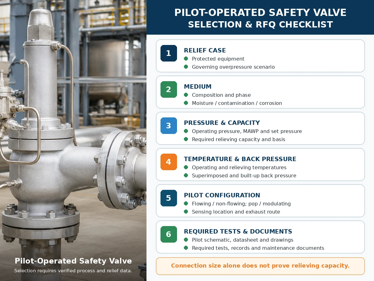
Solo elenco di controllo tecnico. La selezione finale del modello dipende da dati di processo verificati, informazioni del produttore, norme applicabili e revisione del progetto.
Scorrere orizzontalmente per visualizzare tutte le colonne.
| Input richiesto | Perché è Importante | Stato |
|---|---|---|
| Attrezzatura protetta e scenario di sfioro governativo | Definisce il compito di protezione dalla pressione e il carico richiesto. | Da confermare |
| Fluido, composizione e fase | Influisce sul pilota, sulle guarnizioni, sulla gestione dello scarico e sulla base di capacità. | Da confermare |
| Pressione operativa, MAWP/pressione di progetto e pressione di taratura | Definisce il margine operativo e il confine di pressione. | Da confermare |
| Sovrappressione e accumulo ammessi | Influisce sul dimensionamento e sulla base di scarico applicabile. | Da confermare |
| Capacità di sfioro richiesta e base di calcolo | Determina la capacità documentata richiesta della valvola. | Da confermare |
| Temperature operative e di scarico | Controlla i materiali, le guarnizioni, la disposizione del pilota e la base di capacità. | Da confermare |
| Contropressione sovrapposta e accumulata | Influisce sul comportamento della valvola principale e dello scarico del pilota. | Da confermare |
| Con flusso/senza flusso, a scatto/modulante, rilevamento e scarico | Definisce quattro decisioni separate del sistema pilota. | Da confermare |
| Materiali, filtrazione, riscaldamento, drenaggio e accesso per manutenzione | Affronta la compatibilità del servizio e i controlli dei guasti. | Da confermare |
| Codice applicabile, test e documenti | Definisce il pacchetto di prove del progetto. | Da confermare |
Matrice di test e documentazione
I test e la documentazione dovrebbero mostrare diverse parti della catena di prove per la protezione dalla pressione. Un rapporto di prova non dovrebbe essere utilizzato per affermare risultati che non stabilisce.
Scorrere orizzontalmente per visualizzare tutte le colonne.
| Collaudo o Documentazione | Cosa può supportare | Cosa non prova di per sé | Verifica RFQ |
|---|---|---|---|
| Test della pressione di taratura del pilota o della valvola assemblata | Risposta alla pressione di apertura secondo la procedura indicata. | Capacità, risposta alla contropressione in campo o compatibilità del processo. | Specificare il fluido, la procedura, la base di accettazione e il formato del rapporto. |
| Test di tenuta della sede / API 527 test di tenuta sede guida ove applicabile | Perdita nelle condizioni e secondo i criteri dichiarati. | Zero perdite in tutti i servizi o condizioni operative. | Specificare metodo, pressione di prova, fluido e criteri di accettazione. |
| Prova funzionale pilota/valvola principale | Attuazione del pilota, controllo della camera, movimento della valvola principale e ripristino. | Capacità totale in campo o prestazioni dello scarico non testato. | Confermare architettura, tipo di azione e accessori inclusi. |
| Tabella di capacità, certificato o registro di calcolo | Prestazioni di scarico documentate per il progetto selezionato. | Idoneità per una diversa fase, temperatura, contropressione o fluido. | Abbinare modello, orifizio, base del fluido e prova richiesta. |
| Disposizione generale e schema di funzionamento del pilota | Collegamenti, percorsi di flusso, rilevamento, scarico e accessori. | Compatibilità dei materiali o capacità, salvo documentazione separata. | Richiedono la revisione del disegno utilizzata per la produzione e l'installazione. |
| Registri dei materiali | Identità del materiale specificata per i componenti soggetti a pressione e a contatto con il fluido. | Idoneità alla corrosione senza una revisione dei materiali specifica per il servizio. | Definiscono quali componenti e quale livello di rintracciabilità sono richiesti. |
| Scheda tecnica, targhetta e rilascio dell'ispezione. | Configurazione, pressione di taratura, identificazione del modello e stato di ispezione concordato. | Un calcolo di scarico completo o una certificazione universale. | Verifica della coerenza tra ordine di acquisto, disegno, rapporti di prova e targhetta finale. |
| Istruzioni di installazione e manutenzione | Linee guida approvate per tubazioni, rilevamento, scarico, collaudo, manutenzione e ricambi. | Approvazione del progetto quando la disposizione installata differisce dalle istruzioni. | Includere la revisione esatta della serie di prodotto nel pacchetto documentale. |
Registri di riparazione e ripristino: Se richiesto dal programma di riparazione applicabile o dalle specifiche di progetto, conservare i dati di pressione di taratura e tenuta della sede nelle condizioni di arrivo e di uscita, i registri dei pezzi di ricambio, i controlli di risigillatura o targhetta, la tracciabilità e l'approvazione della gestione delle modifiche. Le indicazioni sulla tenuta della sede API 527 non sostituiscono la verifica del dimensionamento o della capacità documentata.
Norme e note sulle fonti
Le evidenze operative specifiche del produttore sono collegate accanto alle dichiarazioni pertinenti di flusso, non flusso e scatto/modulazione sopra riportate. Tali documenti supportano solo le famiglie di prodotti identificate e non devono essere trattati come dati prestazionali universali delle POSRV.
- API 520 Parte I, 10ª Edizione — avviso ufficiale della pubblicazione API per il dimensionamento e la selezione.
- API 520 Parte II, 7ª Edizione — avviso ufficiale della pubblicazione API per l'installazione.
- ASME BPVC Sezione XIII, Edizione 2025 — regole per la protezione dalla sovrappressione.
- ISO 4126-4:2013 — valvole di sicurezza pilotate; ISO elenca la pubblicazione come revisionata e confermata nel 2025.
Questi riferimenti hanno ambiti diversi. Confermare l'edizione adottata dal progetto, il codice dell'apparecchiatura protetta, la giurisdizione, l'ambito produttore/modello e la documentazione richiesta. Un nome di norma non è la prova che ogni modello ZOBAI possieda ogni certificazione.
Domande Frequenti
Qual è la differenza tra una valvola di sicurezza pilotata a flusso continuo e una a flusso non continuo?
Un pilota a flusso continuo mantiene un percorso pilota progettato durante lo stato di scarico stabile rilevante. Un pilota a flusso non continuo interrompe il flusso pilota continuo in condizioni stabili della valvola principale, sebbene possa verificarsi un flusso transitorio durante l'attivazione e la ricarica della camera.
Un pilota a non flusso significa che il fluido di processo non passa mai attraverso il pilota?
N. Il fluido può passare mentre il pilota aziona, modifica la pressione della camera o ripressurizza la camera. Non fluente si riferisce alla condizione stabile, non a ogni istante.
Un pilota a non flusso è sempre migliore di un pilota a flusso?
N. L'idoneità dipende dal fluido, dal percorso di scarico, dalla temperatura, dalla contaminazione, dalla contropressione, dalla capacità richiesta, dal tipo di azione e dal design del produttore selezionato.
Il flusso continuo e il flusso non continuo sono la stessa cosa dell'azione a scatto rispetto a quella modulante?
N. Flusso o non flusso descrive il flusso del circuito pilota. Pop o modulante descrive la risposta di alzata della valvola principale. Specificarli separatamente.
Dove va lo scarico del pilota?
A seconda del design, lo scarico del pilota può andare in atmosfera, all'uscita principale o a un altro percorso chiuso approvato. Verificare lo schema e l'effetto della contropressione.
Quale tipo di pilota è migliore per fluidi di processo pericolosi o di valore?
Un design senza flusso continuo può ridurre la perdita sostenuta del fluido pilota, ma lo scarico transitorio, lo scarico principale, i criteri di tenuta, il percorso e l'idoneità del modello richiedono comunque una verifica.
Una valvola pilota in condizioni di non flusso può comunque subire congelamento o contaminazione?
Sì. Le linee di rilevamento, i filtri, le restrizioni, i passaggi della camera e gli scarichi possono raccogliere umidità, congelare o sporcarsi. Drenaggio, filtrazione e protezione invernale restano specifici per il servizio.
Quali informazioni sono necessarie prima di selezionare l'architettura pilotata?
Fornire l'apparecchiatura protetta, lo scenario di scarico, il fluido di processo e la fase, i dati di pressione, la capacità richiesta, la temperatura di scarico, la contropressione, il rilevamento, lo scarico, le tubazioni, i materiali, il tipo di azione e i documenti richiesti.
Standard e limiti tecnici
L'API 520 Parte I tratta il dimensionamento e la selezione, mentre l'API 520 Parte II tratta l'installazione nei rispettivi ambiti di applicazione. L'ASME BPVC Sezione XIII fornisce un quadro per la protezione dalla sovrappressione. La ISO 4126-4 riguarda le valvole di sicurezza pilotate come norma di prodotto; non è un codice applicativo per il sistema protetto. Verificare l'edizione adottata dal progetto, il codice dell'apparecchiatura applicabile, la giurisdizione e i dati di prodotto specifici del produttore.
La selezione finale dipende dall'apparecchiatura protetta, dallo scenario di scarico prevalente, dal fluido effettivo e dalla fase, dalla pressione di esercizio, dalla MAWP o pressione di progetto, dalla pressione di taratura, dalla capacità di scarico richiesta e documentata, dalla temperatura di scarico, dalla contropressione sovrapposta e accumulata, dalle tubazioni di ingresso e uscita, da tutti i materiali e componenti di tenuta interessati, dalla configurazione del pilota, dall'edizione della norma adottata, dalle specifiche di progetto e dai requisiti normativi locali applicabili.
Richiedi una revisione tecnica della valvola di sicurezza pilotata
La scelta finale tra valvole di sicurezza pilotate a flusso continuo e a flusso non continuo deve seguire lo scenario di scarico effettivo, la capacità richiesta, il fluido e la fase, la temperatura di scarico, la contropressione, la disposizione di rilevamento e scarico, i materiali, la tubazione e la documentazione richiesta. Inviare questi dati prima di richiedere una raccomandazione sul modello.