مقارنة هندسية لصمامات الأمان التي تعمل بالبايلوت: تختلف صمامات الأمان التي تعمل بالبايلوت من حيث التدفق وعدم التدفق بشكل رئيسي في دائرة البايلوت أثناء التنفيس المستقر. يحافظ التصميم المتدفق عادةً على تسريب أو تدفق متحكم به؛ بينما يوقف التصميم غير المتدفق عادةً تدفق البايلوت المستمر بعد وصول الصمام الرئيسي إلى حالة تنفيس مستقرة، على الرغم من أن التدفق العابر يمكن أن يحدث أثناء التشغيل، ...

مقارنة هندسية لصمامات الأمان التي تعمل بالبايلوت
تختلف صمامات الأمان التي تعمل بالبايلوت من حيث التدفق وعدم التدفق بشكل رئيسي في دائرة البايلوت أثناء التنفيس المستقر. يحافظ التصميم المتدفق عادةً على تسريب أو تدفق متحكم به؛ بينما يوقف التصميم غير المتدفق عادةً تدفق البايلوت المستمر بعد وصول الصمام الرئيسي إلى حالة تنفيس مستقرة، على الرغم من أن التدفق العابر يمكن أن يحدث أثناء التشغيل، وضبط الرفع، وإعادة الإغلاق، وإعادة شحن الحجرة. يكون هذا التمييز مهمًا عندما تؤثر عوادم البايلوت، أو الانبعاثات، أو الرطوبة، أو التلوث، أو التجمد، أو الضغط الخلفي، أو التنفيس طويل الأمد على المواصفات. لا يحدد هذا التمييز سلوك الفتح أو التنفيس التدريجي، أو موقع الاستشعار، أو سعة التنفيس. كما أن ضغط الضبط وحجم الوصلة لا يثبتان أن الصمام المختار لديه سعة موثقة كافية. قبل الاختيار، تأكد من المعدات المحمية، وسيناريو التنفيس، والوسط وطوره، وضغط التشغيل، وMAWP أو ضغط التصميم، وضغط الضبط، والسعة المطلوبة، ودرجة حرارة التنفيس، والضغط الخلفي المتراكب والمتولد، ومصدر الاستشعار، ووجهة العادم، والمواد، والمستندات المطلوبة. أرسل هذه الشروط لمراجعة هندسية.
صمامات الأمان التي تعمل بالبايلوت ذات التدفق وغير ذات التدفق: إجابة سريعة
يصف التدفق أو عدم التدفق سلوك وسيط التشغيل عبر دائرة البايلوت. يحافظ البايلوت ذو التدفق عادةً على تدفق مصمم أثناء حالة التنفيس المستقرة ذات الصلة؛ بينما يوقف البايلوت غير ذي التدفق عادةً التدفق المستمر للبايلوت عند الرفع المستقر. لا يحدد أي من المصطلحين حركة الصمام الرئيسي، أو موقع الاستشعار، أو وجهة العادم، أو سعة التنفيس.
يمكن للبايلوت غير المتنفس أن يمرر حجمًا عابرًا أثناء تشغيله أو تغيير ضغط القبة أو إعادة ضغطها. لا ينبغي وصفه بأنه صفر تدفق أو صفر انبعاثات أو بدون صيانة.
راجع البنية المحددة ضمن كامل صمام أمان يعمل بالبايلوت النظام بدلاً من اعتبار تصنيف تدفق البايلوت كمواصفة كاملة.
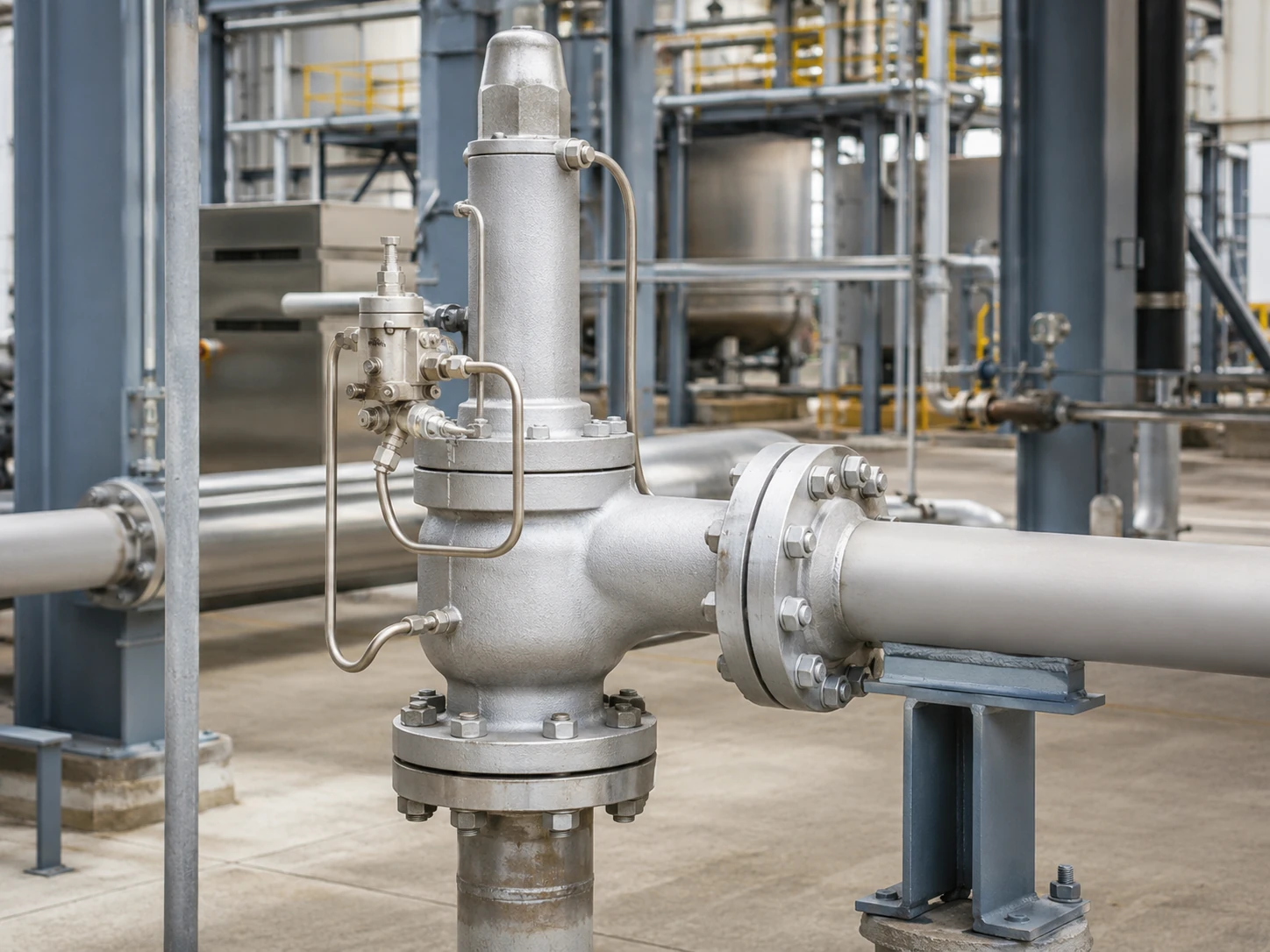
تصور مفاهيمي واقعي. يجب تأكيد هندسة الصمام النهائية، والاستشعار، ومسار التنفيس، ونطاق الضغط، والسعة الموثقة وفقًا للطراز المختار.
حدود الاختيار: لا يوجد نوع بايلوت أفضل بشكل مطلق. لا تحدد بنية البايلوت السعة المطلوبة، أو فتحة التصريف المختارة، أو الضغط الخلفي المقبول، أو توافق المواد، أو ملاءمة الكود. تتطلب هذه القرارات سيناريو التنفيس الحاكم ووثائق الشركة المصنعة المحددة.
مصفوفة الاختيار الأولية
هذه المصفوفة أداة فرز أولي، وليست توصية بطراز معين. وهي تحدد الأسئلة التي يجب حلها قبل تحديد بايلوت متدفق أو غير متدفق.
مرر أفقيًا لمراجعة جميع الأعمدة.
| شرط الخدمة أو المشروع | لماذا هو مهم | مراجعة البايلوت المتدفق | مراجعة البايلوت غير المتدفق | نقطة توقف هندسية |
|---|---|---|---|---|
| عادم البايلوت الجوي المحلي مقيد | قد يكون تنفيس البايلوت غير مقبول للوسائط الخطرة أو القيمة أو المنظمة. | تأكد من تدفق البايلوت المستمر والمسار المعتمد. | تأكد من العادم العابر والحالة المستقرة للطراز المحدد. | أوقف الاختيار حتى يتم تحديد وجهة العادم وتأثيرات ضغط المخرج. |
| قد تكون أحداث التنفيس طويلة | المدة الطويلة يمكن أن تزيد من فقدان وسيط البايلوت وحمل نظام العادم. | اطلب بيانات دورة التشغيل وتدفق البايلوت. | تأكد من وقت توقف التدفق المستمر وكيفية التحكم في الرفع. | المدة وحدها لا تحدد التصميم؛ بل السعة والاستقرار هما العاملان الحاكمان. |
| الغاز الرطب، أو انخفاض درجة الحرارة المحيطة، أو خطر تكون الهيدرات | يمكن أن تتجمد أو تتجمع السوائل في القيود، والمرشحات، وخطوط الاستشعار، ومسارات العادم. | راجع تبريد التمدد، والتصريف، والتدفئة، وحدود درجات الحرارة. | راجع التمدد العابر، وإعادة شحن القبة، وخطوط الاستشعار الرطبة. | انتظر حتى يتم التأكد من التحكم في الرطوبة والحد الأدنى لدرجة الحرارة. |
| وسط يحتوي على شوائب أو مواد بوليمرية أو جسيمات | يمكن أن تنسد أو تلتصق أو تتآكل الممرات الصغيرة والمقاعد. | قيّم التعرض المستمر للقيود والمرشحات. | قيّم المقاعد، والمسارات العابرة، والترشيح، وتلوث القبة. | المرشح وحده لا يجعل الخدمة مقبولة. |
| ضغط مخرج متغير أو مشعب تصريف مشترك | يمكن أن يؤدي تغير الضغط عند المخرج إلى تغيير توازن القوى في عادم البايلوت والصمام الرئيسي. | تأكد من كيفية تأثير الضغط عند المخرج على دائرة العادم ودائرة الحجرة العلوية. | تأكيد سلوك التحكم المستقر في التنفيس، وإعادة الضبط، والتدفق العكسي. | افصل بين الضغط الخلفي المضاف والضغط الخلفي المتراكم. |
| يلزم الاستشعار عن بُعد | يمكن أن يؤثر مسار خط الاستشعار، وفقدان الضغط، والنبض، والتصريف، والعزل على التشغيل. | تأكد من توافق الإشارة عن بُعد مع دائرة البايلوت المحددة. | تأكد من التحكم في القبة والاستجابة العابرة مع ترتيب الاستشعار عن بُعد. | لا تستنتج ملاءمة الاستشعار عن بُعد من تصنيف تدفق البايلوت. |
| من الممكن استخدام خدمة السوائل أو السوائل المتبخرة أو ثنائية الطور | يؤثر سلوك الطور على السعة، وديناميكيات البايلوت، واستقرار التفريغ. | تتطلب موافقة صريحة من الشركة المصنعة للطور الفعلي وحالة التنفيس. | تتطلب موافقة صريحة من الشركة المصنعة للطور الفعلي وحالة التنفيس. | المقارنة بين التدفق وعدم التدفق وحدها غير كافية. |
نقطة تعليق طلب عرض السعر (RFQ): لا تقم بتحويل تفضيل مثل “عدم التدفق المطلوب” إلى اختيار نموذج نهائي حتى تتوفر بيانات حمل التنفيس، والطور، ودرجة حرارة التنفيس، والضغط الخلفي، ومصدر الاستشعار، ووجهة العادم.
كيف يتحكم صمام الأمان الذي يعمل بالبايلوت في الصمام الرئيسي
الصمام الرئيسي، البايلوت، وضغط القبة
يتضمن النظام النموذجي صمام التنفيس الرئيسي، والبايلوت، والقبة أو غرفة التحكم، ومسار الاستشعار، والأنابيب، وعادم البايلوت. تحت ضغط الضبط، يحافظ ضغط العملية عادةً على ضغط القبة وقوة إغلاق الصمام الرئيسي.
عند ضغط الضبط، يغير البايلوت مسار ضغط القبة بحيث يمكن لضغط المدخل فتح الصمام الرئيسي. وعندما ينخفض الضغط نحو ضغط إغلاق البايلوت، يُعاد ضغط القبة ويُعاد إحكام إغلاق الصمام الرئيسي.
ضغط الاستشعار وعادم البايلوت
يمكن استشعار الضغط بشكل متكامل أو عن بُعد. قد يذهب عادم البايلوت إلى الغلاف الجوي، أو مخرج الصمام الرئيسي، أو مسار مغلق آخر معتمد؛ ولا يتم تحديد أي من الخيارين حسب تصنيف التدفق أو عدم التدفق.
تشغيل البايلوت لا يحل محل التحقق من السعة
لا يثبت استجابة ضغط الضبط أن الصمام يمكنه تمرير حمل التنفيس الحاكم. تأكد من السعة المطلوبة، والفتحة المختارة، والسعة الموثقة بشكل منفصل؛ حجم التوصيل ليس أساسًا للسعة. انظر حساب مقاسات صمامات الأمان وسعة التنفيس المعتمدة.
السعة المطلوبة، الصمام المختار، والأدلة أمور مختلفة
تتحكم بنية البايلوت في الصمام الرئيسي، لكنها لا تحل محل سلسلة اختيار السعة. كل عنصر أدناه يجيب على سؤال هندسي مختلف.
قيم السعة للبخار، الهواء أو الغاز، السائل، والطورين ليست قابلة للتبادل. يجب أن يتطابق أساس السعة المختار مع وسيط التنفيس الفعلي، والطور، والضغط، ودرجة الحرارة، والضغط الخلفي، وطريقة الحساب المطبقة.
مرر أفقيًا لمراجعة جميع الأعمدة.
| البند | ما يمثله | الأدلة المطلوبة | ما لا يثبته |
|---|---|---|---|
| سعة التنفيس المطلوبة | حمولة التنفيس من سيناريو الضغط الزائد الحاكم. | أساس الحساب، خصائص المائع، الطور، ضغط ودرجة حرارة التنفيس. | لا يحدد حجم الوصلة أو نوع البايلوت. |
| مساحة التدفق المطلوبة | أقل مساحة فعالة محسوبة لأساس التحديد. | الطريقة المطبقة، المعاملات، الضغط الخلفي وافتراضات المائع. | لا يثبت أن فتحة تجارية معينة لديها سعة موثقة كافية. |
| الفتحة أو تصميم الصمام المختار | هندسة الشركة المصنعة المختارة لتلبية الحمولة المطلوبة. | ورقة بيانات الموديل، تسمية الفتحة ووثائق السعة. | لا يثبت ملاءمة درجة الحرارة أو المادة أو العادم أو الضغط الخلفي. |
| السعة الموثقة أو المعتمدة | الأداء المنشور أو الموثق تحت الظروف المذكورة. | جدول السعة أو الشهادة أو سجل الحساب المطلوب من المشروع. | لا يغني عن التحقق من الوسيط الفعلي وظروف التنفيس. |
| حجم وصلة الدخول والخروج | واجهة الأنابيب ووصلة الفلنجة أو الملولبة. | الترتيب العام ومواصفات التوصيل. | حجم التوصيل وحده لا يثبت سعة التنفيس. |
| اختبار ضغط الضبط | استجابة الضغط للبايلوت والصمام أثناء إجراء الاختبار. | سجل الاختبار المعاير ومعايير القبول المطبقة. | لا يثبت بشكل مستقل سعة الموقع أو ملاءمة الطور أو أداء الضغط الخلفي. |
ملاحظة المراجعة الهندسية: الطلب الذي يحتوي فقط على ضبط الضغط وحجم التوصيل غير مكتمل. سعة التنفيس المطلوبة وأساس حسابها هما مدخلات منفصلة ويجب التعامل معهما كنقاط توقف إلزامية قبل تأكيد الموديل.
حالات التشغيل الأربع التي يجب على المشترين مقارنتها
مرر أفقيًا لمراجعة جميع الأعمدة.
| حالة التشغيل | مراجعة البايلوت المتدفق | مراجعة البايلوت غير المتدفق | الفحص الخاص بالموديل |
|---|---|---|---|
| التشغيل المغلق الطبيعي | تحديد ما إذا كان هناك مسار نزف أو تدوير مصمم. | حدد ما إذا كانت دائرة البايلوت تصبح ثابتة بعد ضغط القبة. | ترتيب مقاعد الإمداد والقبة والعادم. |
| تشغيل البايلوت | حدد كيف يتغير مسار تدفق البايلوت. | حدد الحجم العابر المار عبر البايلوت. | تسلسل التشغيل ومسار تخفيف ضغط القبة. |
| تنفيس ثابت للصمام الرئيسي | تأكد من استمرار تدفق البايلوت. | تأكد من توقف تدفق البايلوت المستمر عند الرفع المستقر. | مخطط التشغيل من الشركة المصنعة. |
| إعادة الإغلاق وإعادة ضغط القبة | تأكد من كيفية إعادة بناء ضغط القبة. | تأكيد تدفق إعادة الشحن العابر وإعادة ضبط البايلوت. | استجابة ضغط الإغلاق، والتفريغ، والضغط الخلفي. |
الحالة 1: التشغيل المغلق العادي
تحت ضغط الضبط، تأكد من حالة مقعد البايلوت، وتصريف خط الاستشعار، وحالة الفلتر، وأي تسرب محتمل في القبة.
الحالة 2: تشغيل البايلوت
عند ضغط الضبط، يحد البايلوت من إمداد القبة ويقلل ضغط القبة. يحدث بعض تدفق البايلوت عادةً أثناء هذا الانتقال، بما في ذلك في التصميم غير المتدفق.
الحالة 3: تنفيس الصمام الرئيسي المستقر
تفصل هذه الحالة التصنيفات: تحافظ التصميمات المتدفقة على مسار البايلوت المقصود، بينما توقف التصميمات غير المتدفقة تدفق البايلوت المستمر عند الرفع المستقر.
الحالة 4: إعادة الإغلاق وإعادة ضغط القبة
عندما ينخفض الضغط، يستعيد البايلوت ضغط القبة. يمكن للبايلوت غير المتدفق أن يمرر تدفق إعادة الشحن العابر قبل إغلاق الصمام الرئيسي.
ما هو البايلوت المتدفق؟
يحافظ البايلوت المتدفق على مسار وسيط العملية المصمم أثناء حالة التنفيس المستقرة ذات الصلة. التدفق صغير مقارنة بالتفريغ الرئيسي ولكنه قد يكون مهمًا للوسائط السامة أو القابلة للاشتعال أو المسببة للتآكل أو القيمة أو الحاملة للرطوبة. أساسيات تشغيل بيكر هيوز تصف الطيارات المتدفقة وغير المتدفقة كمحور تصنيف واحد.
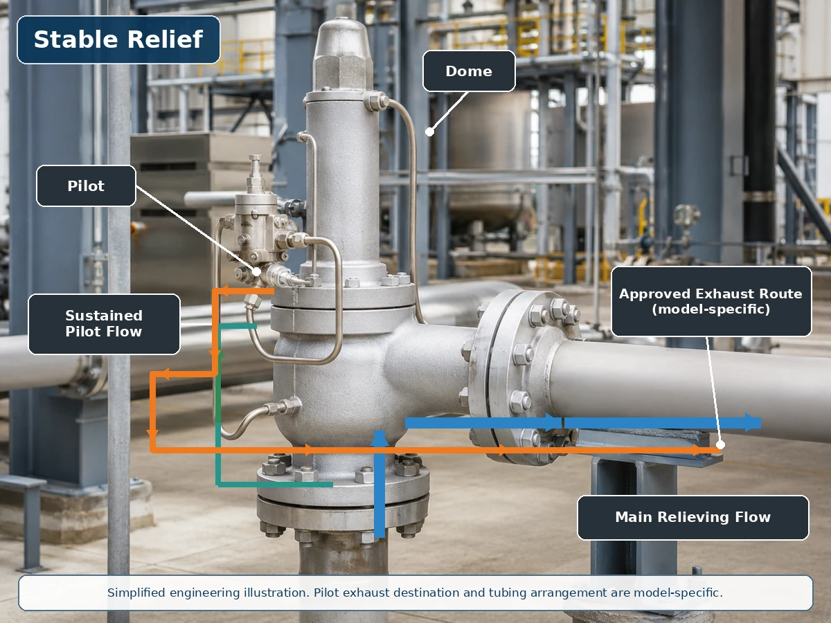
رسم هندسي مبسط يعتمد على تركيب صمام واقعي. مسارات إمداد الطيار والقبة والعادم الفعلية خاصة بالطراز.
مسار التدفق أثناء تنفيس الصمام الرئيسي
أثناء التنفيس، قد يستمر تدفق الطيار في تنفيس أو تنظيم ضغط القبة. تأكد من أساس تدفق الطيار ووجهة العادم وعواقب الخدمة بدلاً من اعتبار التدفق سببًا تلقائيًا للاستبعاد.
عادم الطيار وإعادة الضغط للقبة
تحقق مما إذا كان العادم يذهب إلى الغلاف الجوي أو المخرج أو نظام آخر معتمد، وما إذا كان ضغط المخرج أو المكثف أو التصريف أو التسخين أو التدفئة الشتوية يؤثر عليه.
ما هو الطيار غير المتدفق؟
يصل الطيار غير المتدفق إلى حالة مستقرة يتوقف فيها التدفق المستمر لوسط العملية عبر الطيار بينما قد يظل الصمام الرئيسي مفتوحًا. تظل المقاعد الداخلية وعناصر التغذية الراجعة وتفاصيل التحكم في القبة خاصة بالطراز. دليل Emerson Series 800 يصف حالة التنفيس المستقرة هذه ويلاحظ أيضًا التدفق العابر عندما يغير الطيار الرفع.

رسم توضيحي هندسي مبسط. عدم التدفق لا يعني صفر تدفق عابر، أو صفر تسرب، أو صفر انبعاثات.
التشغيل العابر وتفريغ ضغط القبة
عند ضبط الضغط، يقلل البايلوت ضغط القبة؛ وقد تمر كمية صغيرة من وسط القبة أو العملية خلال هذا الانتقال.
تنفيس مستقر دون تدفق بايلوت مستمر
عند الرفع المستقر، قد يعزل البايلوت الإمداد والعادم بحيث يتوقف تدفق البايلوت المستمر. هذا يمكن أن يقلل الاستهلاك المستمر للوسط ولكنه لا يثبت صفر تسرب ولا يلغي مخاطر التلوث والتجمد.
إعادة الضبط وإعادة شحن القبة
عند انخفاض الضغط، يُعاد فتح مسار إمداد القبة ويحدث تدفق إعادة شحن عابر قبل إغلاق الصمام الرئيسي.
مقارنة البايلوت المتدفق وغير المتدفق
مرر أفقيًا لمراجعة جميع الأعمدة.
| العامل الهندسي | بايلوت متدفق | بايلوت غير متدفق | سؤال حول الاختيار |
|---|---|---|---|
| تدفق بايلوت مستقر أثناء التنفيس | يتم الحفاظ عليه عادةً خلال مرحلة التحكم ذات الصلة. | عادةً ما يكون غائبًا عند رفع الصمام الرئيسي المستقر. | ماذا يُظهر المخطط التشغيلي المحدد؟ |
| تدفق البايلوت العابر | موجود. | موجود أثناء حركة البايلوت أو التحكم في القبة. | ما الحجم ومسار العادم المطبق؟ |
| فقدان وسيط العملية | قد يكون أعلى عبر البايلوت أثناء التنفيس المستمر. | عادةً ما يكون أقل عبر البايلوت عند التنفيس المستقر. | هل الوسيط خطير أو قيّم أو خاضع للتحكم؟ |
| الانبعاثات الجوية | ممكن إذا كان عادم البايلوت مفتوحًا على الغلاف الجوي. | لا يزال ممكنًا أثناء التشغيل إذا تم التنفيس بشكل مفتوح. | أين ينتهي عادم البايلوت؟ |
| التعرض للملوثات | يعتمد على المسار المستمر والقيود والترشيح. | يعتمد على المقاعد والممرات والتدفق العابر والترشيح. | هل الوسط مناسب للبايلوت المحدد؟ |
| التجمد والجليد | قد يكون التمدد المستمر ذا صلة. | التمدد العابر وخطوط الاستشعار الرطبة قد تتجمد مع ذلك. | ما هي درجة الحرارة الدنيا وظروف الرطوبة المطبقة؟ |
| التعرض للضغط الخلفي | يمكن أن يؤثر توجيه العادم على تحكم البايلوت. | يمكن أن يؤثر مسار تصريف العادم أيضًا على التحكم في البايلوت. | هل عادم البايلوت متصل بالمخرج؟ |
| حركة فتح كاملة أو حركة تنظيمية | تصنيف منفصل. | تصنيف منفصل. | ما نوع حركة الصمام الرئيسي المطلوبة؟ |
| سعة التنفيس | لا يتم تحديده حسب نوع تدفق البايلوت. | لا يتم تحديده حسب نوع تدفق البايلوت. | هل السعة الموثقة كافية لحالة التنفيس؟ |
التدفق وعدم التدفق ليسا نفس الشيء مثل الفتح الكامل والتنظيم
تدفق البايلوت، وحركة الصمام الرئيسي، وموقع الاستشعار، ووجهة عادم البايلوت هي قرارات مستقلة. البايلوت المتدفق ليس تلقائيًا من نوع الفتح الكامل، والبايلوت غير المتدفق ليس تلقائيًا من نوع التنظيم. مواصفة Baker Hughes 2900-40 توفر أمثلة خاصة بالمنتج لكل من البايلوتات غير المتدفقة ذات الفتح الكامل والبايلوتات غير المتدفقة ذات الحركة التنظيمية؛; نظرة عامة على صمامات الأمان التي تعمل بالبايلوت من LESER يشرح بشكل منفصل سلوك الرفع المفاجئ والرفع التعديلي.
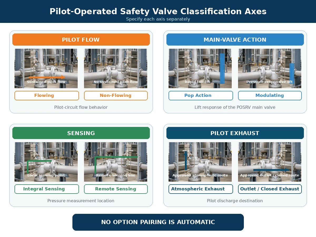
مقارنة هندسية مبسطة. التركيبات المتاحة تعتمد على الشركة المصنعة المختارة وسلسلة المنتجات.
مرر أفقيًا لمراجعة جميع الأعمدة.
| محور التصنيف | خيارات نموذجية | ما يصفه | ما لا يصفه |
|---|---|---|---|
| تدفق البايلوت | تدفق / عدم تدفق | سلوك وسيط العملية عبر دائرة البايلوت. | خاصية رفع الصمام الرئيسي. |
| إجراء الصمام الرئيسي | رفع مفاجئ / تعديلي | فتح كامل سريع أو رفع يستجيب للضغط. | ما إذا كان تدفق البايلوت مستمرًا. |
| ترتيب الاستشعار | مدمج / عن بُعد | حيث يقيس البايلوت ضغط النظام المحمي. | وجهة تفريغ البايلوت. |
| ترتيب التفريغ | الغلاف الجوي / المخرج / مسار مغلق معتمد | حيث يتم تفريغ وسيط البايلوت. | إجراء الصمام الرئيسي أو سعة التنفيس. |
كيف يؤثر تفريغ البايلوت والضغط الخلفي على القرار
التفريغ إلى الغلاف الجوي مقابل التفريغ إلى المخرج
قد يكون تفريغ البايلوت إلى الغلاف الجوي غير مقبول للوسائط السامة أو القابلة للاشتعال أو المسببة للتآكل أو ذات الرائحة أو الخاضعة للتحكم البيئي أو القيمة. يمكن أن يؤدي توجيه التفريغ إلى مخرج الصمام الرئيسي إلى تقليل الإطلاق المحلي في الغلاف الجوي، ولكنه قد يعرض اتصال تفريغ البايلوت لضغط المخرج.
الضغط الخلفي المتراكب والضغط الخلفي المتراكم
الضغط الخلفي المتراكب موجود قبل فتح الصمام. يتطور الضغط الخلفي المتولد بسبب تدفق التنفيس عبر نظام المخرج بعد الفتح. يمكن أن تؤثر أي من الحالتين على توازن القوى في الصمام الرئيسي، وتفريغ البايلوت، وتقليل ضغط القبة، والرفع، وإعادة الإغلاق، والتدفق العكسي. راجع هذه التأثيرات مع دليل ZOBAI إلى الضغط الخلفي والمنفاخ.
مرر أفقيًا لمراجعة جميع الأعمدة.
| الحالة | البيانات المطلوبة | سؤال دائرة البايلوت | حد القرار |
|---|---|---|---|
| ضغط خلفي متراكب ثابت | ضغط المخرج قبل الفتح. | هل يؤثر على العادم، الصمام الرئيسي أم كلاهما؟ | تأكد من حد الطراز وأساس السعة. |
| ضغط خلفي متراكب متغير | ملف ضغط المخرج الأدنى والطبيعي والأقصى. | هل يمكن أن يؤثر التغير على الفتح أو الرفع أو الاستقرار أو إعادة الإغلاق؟ | لا تعتمد على قيمة متوسطة واحدة. |
| الضغط الخلفي المتراكم | حساب نظام التفريغ عند معدل التنفيس الحاكم. | هل يمكن أن يقيد عادم البايلوت أو يقلل من أداء الصمام الرئيسي؟ | قيّم عند التدفق المطلوب، وليس عند التشغيل العادي. |
| عادم البايلوت متصل بالمخرج الرئيسي | ضغط المخرج أثناء الفتح والتنفيس وإعادة الإغلاق. | كيف تتأثر عملية تخفيف الضغط في القبة وإعادة الضبط؟ | مطلوب مخطط العادم المعتمد. |
| قد يتجاوز ضغط المخرج ضغط المدخل أو ضغط القبة | فرق الضغط العكسي المحتمل وتسلسل التشغيل. | هل هناك حاجة لمنع التدفق العكسي أو أي تحكم آخر؟ | لا تفترض أن ترتيب البايلوت القياسي يمنع التدفق العكسي. |
حماية التدفق العكسي ودائرة البايلوت
إذا تجاوز ضغط المخرج ضغط المدخل أو ضغط القبة، فقد يدخل وسيط التفريغ إلى القبة أو دائرة البايلوت أو يسبب قوة فتح غير مقصودة للصمام الرئيسي. قد تشمل وسائل التحكم الخاصة بالشركة المصنعة أجهزة فحص، ومنع التدفق العكسي، وترتيبات عادم معتمدة.
مخاطر الوسيط ودرجة الحرارة والتلوث
الغاز النظيف والبخار
الغاز الجاف النظيف يقلل من بعض مخاوف التصريف والترسبات، ولكن لا يزال يتطلب مراجعة التركيب ودرجة حرارة التمدد والأختام وتصنيف العادم.
التكثيف والتجمد والهيدرات
الرطوبة والممرات الصغيرة والنقاط المنخفضة يمكن أن تسبب تكاثفًا أو تجمدًا أو هيدرات. التشغيل غير المتدفق لا يلغي متطلبات التصريف والحماية من الشتاء.
وسائط متسخة أو متصلبة
الصدأ والقشور والجسيمات والشمع والرواسب يمكن أن تقيد مكونات البايلوت. يجب أن تكون المرشحات مناسبة ويمكن الوصول إليها وصيانتها.
درجة الحرارة والإجراءات المساعدة
راجع جميع مكونات البايلوت والصمام الرئيسي المتأثرة، وليس فقط مادة الجسم: الأجزاء المبللة، والفوهة، والقرص، والدليل، والأنابيب، والنابض، والمقعد/المانع، والغشاء، وأي منفاخ مستخدم في تكوين الصمام الرئيسي المحدد. قد يكون التركيب عن بُعد أو التسخين أو التبريد أو مواد مختلفة مطلوبًا.
مرر أفقيًا لمراجعة جميع الأعمدة.
| الوسيط أو الحالة | مخاطر نظام البايلوت | عناصر يجب تأكيدها | متى لا يتم المتابعة دون مراجعة |
|---|---|---|---|
| غاز أو بخار نظيف وجاف | تبريد التمدد والأختام والعادم الخطير لا تزال مهمة. | جسم البايلوت والأنابيب والمقاعد والأختام ودرجة الحرارة الدنيا ومسار العادم. | عندما يكون التركيب أو درجة حرارة التنفيس أو فئة العادم غير معروفة. |
| غاز رطب أو بخار قابل للتكثف | المكثفات، التجمد، الهيدرات، ومسارات الاستشعار المسدودة. | التوجيه ذاتي التصريف، النقاط المنخفضة، المصارف، التدفئة، وموقع الفلتر. | عندما لا يمكن تصريف خطوط الاستشعار والعادم أو حمايتها من التجمد. |
| وسط متسخ أو يحتوي على جسيمات. | القيود المسدودة، المقاعد التالفة، الفلاتر المسدودة، وتلوث الحجرة. | خصائص الجسيمات، الترشيح، حجم الممر، وإمكانية الوصول للصيانة. | عندما تكون الملاءمة أو استراتيجية الحماية القابلة للصيانة غير موثقة. |
| وسط أكّال | هجوم على جسم البايلوت، الأنابيب، الأجزاء المبللة، المقاعد، والأختام اللينة. | المواد، الأنابيب، توافق المقعد/الختم، والسجلات. | عندما يعتمد المراجعة فقط على مادة جسم الصمام الرئيسي. |
| خدمة البلمرة أو التبلور أو التصلب. | الالتصاق، الممرات المسدودة، الرواسب، وضعف التحكم في الحجرة. | التحكم في درجة الحرارة، التنظيف/الطرد، الأجزاء الميتة وأساس الصيانة. | عندما يمكن أن تتشكل رواسب في ممرات يتعذر الوصول إليها. |
| خدمة درجات الحرارة العالية أو المنخفضة | قد تتعرض زنبرك البايلوت، المقاعد، الأختام، الغشاء، الأنابيب والمرشحات لدرجات حرارة مختلفة عن الجسم الرئيسي. | درجات حرارة التشغيل والتنفيس، الظروف البيئية القصوى، التركيب عن بعد، ترتيبات التسخين أو التبريد. | عندما يتم فحص تصنيف درجة حرارة جسم الصمام الرئيسي فقط. |
| خدمة السائل أو السائل المتبخر أو ثنائي الطور | قد تختلف الاستجابة الديناميكية، أساس السعة واستقرار البايلوت عن خدمة الغاز. | أساس الطور الدقيق، ظروف التنفيس وموافقة صريحة من الشركة المصنعة. | عندما يتم افتراض الطور بدلاً من حسابه أو تأكيده. |
ضوابط التركيب: ما يجب فعله وما يجب تجنبه
لا يمكن لبنية البايلوت أن تعمل كما هو مقصود إلا عندما يتم تركيب مدخل الصمام الرئيسي، المخرج، خط الاستشعار، أنبوب القبة وعادم البايلوت كنظام متكامل للحماية من الضغط. للحصول على ضوابط تفصيلية للمدخل، المخرج، الدعم وخط الاستشعار، استخدم دليل تركيب صمامات الأمان.
افعل
- اجعل مدخل الصمام الرئيسي قصيرًا ومباشرًا وقم بتقييم فقد الضغط عند المدخل لحالة التنفيس الحاكمة.
- ادعم خط المخرج بشكل مستقل وراجع قوة رد الفعل للتفريغ والحركة الحرارية وأحمال المجمع.
- وجّه خطوط الاستشعار عن بُعد لتقليل فقد الضغط والاهتزاز والتجمعات السائلة والعزل العرضي.
- ادعم أنابيب البايلوت وحافظ على القطر الداخلي المطلوب من الشركة المصنعة والتجهيزات ونقاط التوصيل.
- وجّه عادم البايلوت إلى وجهة آمنة معتمدة وقم بتقييم الضغط المفروض على هذا المسار.
- وفّر التصريف أو التسخين أو العزل أو الحماية البيئية حيث تتطلب الخدمة وتعليمات الشركة المصنعة ذلك.
- أبقِ فتحات التهوية والتصريف والمرشحات ووصلات الاختبار ووصلات الصيانة في متناول اليد.
ممنوع
- لا تقم بتوصيل خط الاستشعار بنقطة عشوائية أو تفترض أن ضغط المخرج هو ضغط النظام المحمي.
- لا تضف صمامات عزل إلى خطوط الاستشعار أو البايلوت دون ترتيب معتمد مقفل أو متحكم فيه.
- لا تقلل حجم الأنابيب أو تضيف مسافات طويلة غير مدعومة أو تنشئ نقاطًا منخفضة دون مراجعة تأثير الاستجابة.
- لا تقم بسد أو توصيل أو دمج فتحة تهوية أو تصريف البايلوت إلا إذا كان التصميم المحدد يسمح بذلك صراحةً.
- لا تدع الصمام الرئيسي يتحمل وزن أو أحمال رد الفعل لأنابيب التفريغ الثقيلة.
- لا تعامل التدفئة الحرارية أو التطهير أو المرشحات كحلول عامة لوسط غير مناسب.
- لا تغير مسار العادم دون التحقق من الضغط الخلفي ومتطلبات المناطق الخطرة والبيئة.
نقطة توقف التثبيت: أي تغيير في موقع الاستشعار أو أنابيب البايلوت أو مسار العادم أو مشعب المخرج أو فلسفة العزل يتطلب مراجعة خاصة بالشركة المصنعة والمشروع قبل التشغيل.
أنماط الفشل الشائعة وفحوصات الصيانة
مرر أفقيًا لمراجعة جميع الأعمدة.
| العرض الملاحظ | سبب محتمل في دائرة البايلوت | سبب محتمل آخر | تحقق مطلوب |
|---|---|---|---|
| يفتح الصمام الرئيسي متأخرًا | خط استشعار مسدود أو مدخل بايلوت مسدود. | قياس ضغط غير صحيح أو مشكلة في ضبط الضغط. | تحقق من مسار الاستشعار وبيانات الاختبار المعايرة. |
| يفتح الصمام الرئيسي مبكرًا | تسرب في مقعد البايلوت أو إعداد بايلوت غير صحيح. | نبض الضغط أو نقطة استشعار غير مناسبة. | افحص البايلوت ومصدر الضغط. |
| الصمام الرئيسي لا يصل إلى الرفع المتوقع | تقييد عادم البايلوت أو عدم كفاية تخفيف الضغط في القبة. | تدفق عملية غير كافٍ أو ضغط خلفي زائد. | راجع عادم البايلوت والنظام المركب. |
| الصمام الرئيسي يدور | عدم استقرار البايلوت أو نبض في خط الاستشعار. | حجم كبير، فقدان في المدخل أو ضغط خلفي متغير. | راجع نظام التنفيس بالكامل. |
| إعادة الإغلاق ببطء | مسار إعادة شحن القبة مقيد. | احتكاك في الصمام الرئيسي أو نفخ غير مناسب. | افحص البايلوت والصمام الرئيسي. |
| تجمد منفذ البايلوت | وسط رطب وتبريد تمددي. | التعرض للبيئة المحيطة أو سوء التصريف. | راجع التحكم في الرطوبة والتجهيزات الشتوية. |
لا تشخص من العَرَض وحده. يمكن أن يكون سبب الصمام الذي يدور، أو يفتح متأخرًا، أو يرفع منخفضًا هو دائرة البايلوت، ولكن يمكن أن ينتج أيضًا عن فقدان ضغط المدخل، أو زيادة حجم الصمام، أو عدم كفاية تدفق العملية، أو الضغط الخلفي المتغير، أو احتكاك الصمام الرئيسي، أو موقع استشعار غير مناسب. احتفظ بسجلات الضغط، وحالة البايلوت، وتكوين الأنابيب، وأدلة الاختبار قبل تغيير إعداد البايلوت.
يجب أن تتبع الصيانة إجراءً معتمدًا للعزل، وتخفيف الضغط، والاختبار. لا تقم بسد منافذ البايلوت أو المصارف، أو تعديل الأنابيب دون الحفاظ على التصميم المطلوب، أو استنتاج سعة التنفيس من اختبار ضبط الضغط.
سير عمل لاتخاذ القرار لاختيار بنية البايلوت
1. تحديد حالة التنفيس
- المعدات المحمية وسيناريو الضغط الزائد الحاكم؛ استخدم أنظمة تنفيس الضغط API 521 الدليل عندما يعتمد أساس المشروع على API 521
- ضغط التشغيل، أو MAWP، أو ضغط التصميم، وضبط الضغط
- الضغط الزائد المسموح به والتراكم
- سعة التنفيس المطلوبة وأساس الحساب
- ضغط التنفيس، درجة حرارة التنفيس، الوسط والطور
2. تحديد متطلبات تدفق البايلوت والعادم
- ما إذا كان تدفق البايلوت المستمر مقبولاً
- متطلبات العادم إلى الغلاف الجوي أو المخرج أو المغلق
- حركة فتح كاملة أو حركة تنظيمية
- الاستشعار المدمج أو عن بُعد
- منع التدفق العكسي ومتطلبات الاختبار الميداني
3. مراجعة مخاطر الخدمة والفشل
- التلوث والتآكل والتصلب
- التكاثف والتجمد وتكوين الهيدرات
- الاهتزاز والنبض وترتيب خط الاستشعار
- التعرض البيئي وإمكانية الوصول للصيانة
4. تأكيد التصميم الخاص بالشركة المصنعة
- مخطط تشغيل البايلوت وورقة بيانات الطراز
- حدود الضغط ودرجة الحرارة والطور والضغط الخلفي
- المواد والأختام والمرشحات والسخانات والمصارف
- السعة الموثقة والمستندات المطلوبة للمشروع
عندما لا يكون هذا المقارنة كافيًا
لا تختار صمامًا بناءً على مقارنة التدفق/عدم التدفق وحدها عندما يظل أي مما يلي غير محسوم:
- لم يتم تحديد المعدات المحمية أو سيناريو التنفيس الحاكم.
- السعة المطلوبة للتنفيس أو ضغط التنفيس أو درجة حرارة التنفيس أو أساس الطور مفقود.
- الضغط الخلفي المتراكب أو الناتج متغير أو غير معروف أو متأثر بمشعب مشترك.
- يمكن أن يتجمد الوسط أو يتبلمر أو يتبلور أو يتآكل أو يلوث أو يحمل مواد صلبة.
- مطلوب استشعار عن بعد أو عادم بايلوت مغلق أو منع التدفق العكسي أو اختبار ميداني.
- مخطط البايلوت الأصلي للصمام البديل أو مسار العادم أو مصدر الاستشعار غير متوفر.
- لم تؤكد الشركة المصنعة المختارة الخدمة والمواد ووظيفة البايلوت والملحقات.
قاعدة القرار: عندما يمكن أن يؤدي إدخال مفقود إلى تغيير السعة أو استقرار البايلوت أو سلامة العادم أو توافق المواد أو قبول الكود، قم بتسجيله على أنه “يحتاج إلى تأكيد” بدلاً من تحويله إلى حقيقة مفترضة.
سيناريوهات هندسية مركبة
السيناريوهات التالية هي أمثلة تدريبية مركبة. وهي لا تمثل عملاء محددين أو حوادث موثقة أو مشاريع ZOBAI مكتملة.
غاز نظيف عالي الضغط مع قيود على الانبعاثات الجوية
المشكلة الملاحظة: يحدد طلب عرض الأسعار “عدم التدفق المطلوب” فقط لأن الانبعاثات الجوية المحلية مقيدة. السبب الهندسي: يعامل الطلب تدفق البايلوت المستقر كما لو كان مسار التحرير الوحيد الممكن. التصحيح: قارن عادم البايلوت العابر، وتدفق البايلوت المستقر، وتفريغ الصمام الرئيسي، وتوجيه العادم، والضغط الخلفي، والسعة الموثقة. الوقاية: اطلب مخطط البايلوت المحدد ووجهة عادم معتمدة قبل الموافقة على الطراز.
غاز رطب مع تكاثف وخطر تجمد
المشكلة الملاحظة: يستجيب بايلوت الغاز الرطب ببطء أو يصبح غير مستقر أثناء انخفاض درجة الحرارة المحيطة. السبب الهندسي: تتجمع الرطوبة في نقاط منخفضة في مسار الاستشعار أو العادم وتتجمد أثناء تخفيض الضغط. التصحيح: استعد التوجيه الذاتي التصريف وطبق ترتيب التصريف أو التسخين أو التجهيز الشتوي المعتمد من الشركة المصنعة. الوقاية: تأكد من الحد الأدنى لدرجة الحرارة، وحالة الرطوبة، ومسار الخط، والمرشحات، وإمكانية الوصول للصيانة أثناء مراجعة التصميم.
صمام بديل مع مسار تنفيس البايلوت غير مؤكد
المشكلة الملاحظة: صمام أمان يعمل بالبايلوت بديل يطابق مقاسات الفلنجات وضغط الضبط ولكنه لا يعيد إنتاج سلوك التشغيل الأصلي. السبب الهندسي: لم يتم التحقق من نوع البايلوت الأصلي، أو مصدر الاستشعار، أو مسار التنفيس، أو أساس السعة، أو حالة الضغط الخلفي. التصحيح: أعد بناء أساس التنفيس وقارن المخطط التشغيلي الكامل والسعة الموثقة. الوقاية: تحكم في الاستبدالات من خلال إدارة التغيير، والرسومات المعتمدة، وسجلات الاختبار، وبيانات لوحة الاسم، وإمكانية التتبع.
سير عمل التحقق من الاستبدال
لا ينبغي استبدال صمام الأمان الذي يعمل بالبايلوت بمطابقة المظهر وحجم المدخل وحجم المخرج وضغط الضبط فقط.
أعد بناء أساس الحماية من الضغط
تأكد من المعدات المحمية، وسيناريو التنفيس الحاكم، وMAWP أو ضغط التصميم، وضغط الضبط، والضغط الزائد المسموح به، والسعة المطلوبة، وظروف التنفيس.
حدد بنية البايلوت الأصلية
احصل على ورقة البيانات الأصلية، ولوحة الاسم، والمخطط التشغيلي، وتعليمات الصيانة. أكد ما إذا كان التدفق أو عدم التدفق، أو الفتح المفاجئ أو التعديلي، ومصدر الاستشعار ومسار التنفيس.
تحقق من التوصيلات المثبتة
تتبع خط إمداد البايلوت، خط القبة، خط الاستشعار، العادم، المصارف، المرشحات، السخانات، وصلات الاختبار وأي أجهزة لمنع التدفق العكسي.
قارن ظروف التشغيل الفعلية
راجع الوسط، الطور، التلوث، درجات حرارة التشغيل والتنفيس، الضغط الخلفي المتراكب والمتولد، الظروف المحيطة ومتطلبات العادم الخطرة.
تحقق من السعة واستجابة الضغط بشكل منفصل
طابق السعة المطلوبة مع السعة الموثقة للصمام المقترح وتأكد من ضبط الضغط، والتفريغ، ونوع الإجراء وفقًا لأساس المشروع.
اعتمد اختلافات التركيب
لا تغير نقطة الاستشعار، أو الأنابيب، أو عادم البايلوت، أو ترتيب المخرج، أو المواد، أو الملحقات دون مراجعة موثقة.
حدد أدلة الاختبار والإفراج
اتفق على اختبار ضبط الضغط، وإحكام المقعد، والفحوصات الوظيفية، وسجلات المواد، وأدلة السعة، والرسومات، والأدلة، وفحص الإفراج قبل الشحن أو التشغيل.
ما يجب على المشترين وضعه في ورقة البيانات وطلب عرض الأسعار
تحديد “صمام أمان يعمل بالبايلوت” وحجم المدخل وضبط الضغط فقط ليس كافيًا. يحتاج المورد إلى متطلبات كاملة للعملية، والتنفيس، ودائرة البايلوت، والمستندات.
فجوة شائعة في طلب عرض الأسعار: غالبًا ما تحدد الطلبات “يعمل بالبايلوت” وضغط الضبط وحجم الوصلة ولكنها تحذف سيناريو التنفيس والسعة المطلوبة ودرجة حرارة التنفيس والضغط الخلفي ومصدر الاستشعار ووجهة عادم البايلوت. يجب أن يوقف هذا الحذف تأكيد الموديل بدلاً من ملئه بالافتراضات.
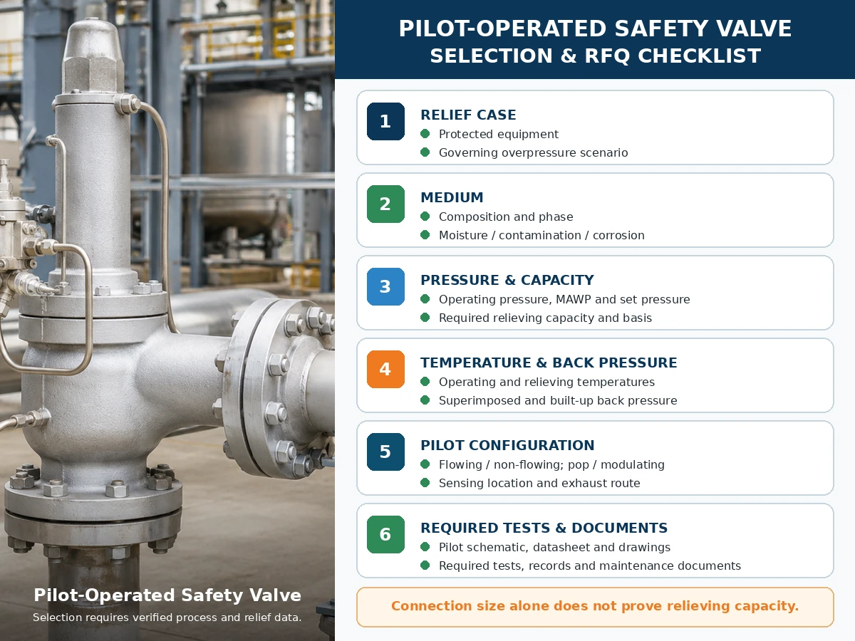
قائمة مراجعة هندسية فقط. يعتمد اختيار الموديل النهائي على بيانات العملية الموثقة ومعلومات الشركة المصنعة والمعايير المطبقة ومراجعة المشروع.
مرر أفقيًا لمراجعة جميع الأعمدة.
| المدخلات المطلوبة | لماذا هو مهم | الحالة |
|---|---|---|
| المعدات المحمية وسيناريو التنفيس الحاكم | يحدد مهمة الحماية من الضغط والحمل المطلوب. | سيتم التأكيد |
| الوسط، التركيب، والحالة الفيزيائية | يؤثر على البايلوت والأختام ومعالجة العادم وأساس السعة. | سيتم التأكيد |
| ضغط التشغيل، أقصى ضغط تشغيل آمن/ضغط التصميم، وضغط الضبط | يحدد هامش التشغيل وحدود الضغط. | سيتم التأكيد |
| الضغط الزائد المسموح به والتراكم | يؤثر على الحساب وأساس التنفيس المطبق. | سيتم التأكيد |
| سعة التنفيس المطلوبة وأساس الحساب | يحدد سعة الصمام الموثقة المطلوبة. | سيتم التأكيد |
| درجات حرارة التشغيل والتنفيس | يتحكم في المواد والأختام وترتيب البايلوت وأساس السعة. | سيتم التأكيد |
| الضغط الخلفي المتراكب والمتزايد | يؤثر على سلوك الصمام الرئيسي وعادم البايلوت. | سيتم التأكيد |
| تدفق/عدم تدفق، فتح مفاجئ/تدريجي، استشعار وعادم | يحدد أربعة قرارات منفصلة لنظام البايلوت. | سيتم التأكيد |
| المواد، الترشيح، التسخين، التصريف، وإمكانية الوصول للصيانة | يعالج توافق الخدمة وضوابط الفشل. | سيتم التأكيد |
| الكود المطبق والاختبار والمستندات | يحدد حزمة أدلة المشروع. | سيتم التأكيد |
مصفوفة الاختبار والتوثيق
يجب أن يُظهر الاختبار والتوثيق أجزاء مختلفة من سلسلة أدلة الحماية من الضغط. لا ينبغي استخدام تقرير اختبار واحد للمطالبة بنتائج لا يثبتها.
مرر أفقيًا لمراجعة جميع الأعمدة.
| اختبار أو وثيقة | ما يمكن أن يدعمه | ما لا يثبته بنفسه | فحص طلب عرض السعر |
|---|---|---|---|
| اختبار ضبط صمام الأمان بالبايلوت أو الصمام المُجمّع | استجابة فتح الصمام وفقًا للإجراء المحدد. | السعة، أو استجابة الضغط الخلفي الميداني، أو التوافق مع العملية. | حدد الوسيط، والإجراء، وأساس القبول، وتنسيق التقرير. |
| اختبار إحكام المقعد / اختبار إحكام المقعد API 527 إرشادات عند الاقتضاء | التسرب في ظل الظروف والمعايير المحددة. | عدم التسرب في جميع الخدمات أو ظروف التشغيل. | حدد الطريقة وضغط الاختبار والوسط ومعايير القبول. |
| اختبار وظيفي للبايلوت والصمام الرئيسي | تشغيل البايلوت، التحكم في القبة، حركة الصمام الرئيسي وإعادة الضبط. | أداء السعة الكاملة في الموقع أو أداء مشعب التفريغ غير المختبر. | تأكد من التصميم ونوع الإجراء والملحقات المضمنة. |
| جدول السعة أو الشهادة أو سجل الحساب | أداء تخفيف موثق للتصميم المحدد. | الملاءمة لطور مختلف أو درجة حرارة أو ضغط خلفي أو وسط. | طابق الطراز والفتحة وأساس المائع والأدلة المطلوبة. |
| الترتيب العام ومخطط تشغيل البايلوت | التوصيلات ومسارات التدفق والاستشعار والعادم والملحقات. | توافق المواد أو السعة ما لم يتم توثيقها بشكل منفصل. | يتطلب مراجعة الرسم المستخدمة في التصنيع والتركيب. |
| سجلات المواد | هوية المواد المحددة للأجزاء المدرجة التي تتحمل الضغط والأجزاء الملامسة للوسط. | ملاءمة التآكل دون مراجعة مواد خاصة بالخدمة. | تحديد المكونات ومستوى التتبع المطلوب. |
| ورقة البيانات، اللوحة الاسمية، وإصدار الفحص. | التكوين، ضبط الضغط، تحديد الطراز، وحالة الفحص المتفق عليها. | حساب تنفيس كامل أو شهادة عامة. | التحقق من الاتساق عبر أمر الشراء والرسم وتقارير الاختبار واللوحة الاسمية النهائية. |
| تعليمات التركيب والصيانة | إرشادات معتمدة للأنابيب والاستشعار والعادم والاختبار والصيانة وقطع الغيار. | موافقة المشروع عندما يختلف الترتيب المركب عن التعليمات. | قم بتضمين مراجعة سلسلة المنتج الدقيقة في حزمة المستندات. |
سجلات الإصلاح وإعادة الضبط: حيثما تتطلب برنامج الإصلاح المطبق أو مواصفات المشروع، احتفظ ببيانات ضبط الضغط وتسرب المقعد كما وُجدت وكما تُركت، وسجلات قطع الغيار، وضوابط إعادة الختم أو لوحة الاسم، وإمكانية التتبع، وموافقة إدارة التغيير. لا يحل إرشاد تسرب المقعد وفق API 527 محل التحقق من الحجم أو السعة الموثقة.
المعايير وملاحظات المصادر
الأدلة التشغيلية الخاصة بالشركة المصنعة مرتبطة بجانب العبارات ذات الصلة الخاصة بالتدفق وعدم التدفق والانفجار/التعديل أعلاه. تدعم هذه المستندات فقط عائلات المنتجات المحددة ويجب ألا تُعتبر بيانات أداء عامة لصمامات POSRV.
- API 520 الجزء الأول، الإصدار العاشر — إشعار منشور رسمي لاختيار وحساب API.
- API 520 الجزء الثاني، الإصدار السابع — إشعار منشور رسمي لتركيب API.
- ASME BPVC القسم XIII، إصدار 2025 — قواعد الحماية من الضغط الزائد.
- ISO 4126-4:2013 — صمامات الأمان التي تعمل بالبايلوت؛ يدرج ISO المنشور كمراجع ومؤكد في 2025.
لهذه المراجع نطاقات مختلفة. أكد إصدار المشروع المعتمد، وكود المعدات المحمية، والسلطة المختصة، ونطاق الشركة المصنعة/الطراز، والوثائق المطلوبة. اسم المعيار ليس دليلاً على أن كل طراز من ZOBAI يحمل كل شهادة.
أسئلة متكررة
ما الفرق بين صمام الأمان الذي يعمل بالبايلوت ذو التدفق وصمام الأمان الذي يعمل بالبايلوت غير ذو التدفق؟
يحافظ البايلوت المتدفق على مسار بايلوت مصمم أثناء حالة التنفيس المستقرة ذات الصلة. أما البايلوت غير المتدفق فيوقف تدفق البايلوت المستمر عند حالة الصمام الرئيسي المستقرة، على الرغم من إمكانية حدوث تدفق عابر أثناء التشغيل وإعادة شحن القبة.
هل يعني عدم تدفق البايلوت أن وسيط العملية لا يمر عبر البايلوت أبدًا؟
لا يمكن للمائع أن يمر أثناء تشغيل البايلوت أو تغيير ضغط القبة أو إعادة الضغط فيها. يشير مصطلح عدم التدفق إلى الحالة المستقرة، وليس إلى كل لحظة.
هل يكون البايلوت غير المار للتدفق دائمًا أفضل من البايلوت المار للتدفق؟
لا. تعتمد الملاءمة على الوسط، ومسار التفريغ، ودرجة الحرارة، والتلوث، والضغط الخلفي، والسعة المطلوبة، ونوع الفعل، وتصميم الشركة المصنعة المختار.
هل التدفق مقابل عدم التدفق هو نفسه الفعل الفوري مقابل التعديل؟
رقم. التدفق أو عدم التدفق يصف تدفق دائرة البايلوت. الانفتاح الكامل أو التعديلي يصف استجابة رفع الصمام الرئيسي. حددها بشكل منفصل.
إلى أين يتجه عادم البايلوت؟
اعتمادًا على التصميم، قد يتم تفريغ عادم البايلوت إلى الغلاف الجوي أو إلى المخرج الرئيسي أو إلى مسار مغلق معتمد آخر. تأكد من المخطط وتأثير الضغط الخلفي.
أي نوع من أنواع البايلوت أفضل للوسائط الخطرة أو القيمة في العمليات؟
قد يقلل التصميم غير المتدفق من فقدان وسيط البايلوت المستمر، لكن لا يزال يتطلب مراجعة العادم العابر، والتفريغ الرئيسي، ومعايير التسرب، والمسارات، وملاءمة الطراز.
هل يمكن أن يتعرض البايلوت غير المتدفق للتجمد أو التلوث؟
نعم. يمكن أن تتجمع الرطوبة أو تتجمد أو تتسخ في خطوط الاستشعار والمرشحات وممرات الحجرة ومنافذ العادم. يبقى التصريف والترشيح والتجهيزات الشتوية حسب طبيعة الخدمة.
ما هي المعلومات المطلوبة قبل اختيار تصميم البايلوت؟
قم بتوفير المعدات المحمية، وسيناريو التنفيس، والوسط وطوره، وبيانات الضغط، والسعة المطلوبة، ودرجة حرارة التنفيس، والضغط الخلفي، والاستشعار، والعادم، والأنابيب، والمواد، ونوع التشغيل، والمستندات المطلوبة.
المعايير والقيود الهندسية
يتناول API 520 الجزء الأول حساب المقاسات والاختيار، بينما يتناول API 520 الجزء الثاني التركيب ضمن نطاقهما المعلن. يوفر ASME BPVC القسم الثالث عشر إطارًا للحماية من الضغط الزائد. يتناول ISO 4126-4 صمامات الأمان التي تعمل بالبايلوت كمعيار منتج؛ وليس كود تطبيق للنظام المحمي. تحقق من الإصدار المعتمد في المشروع، وكود المعدات المعمول به، والجهة التنظيمية، والبيانات الخاصة بالمنتج من الشركة المصنعة.
يعتمد الاختيار النهائي على المعدات المحمية، وسيناريو التنفيس الحاكم، والوسط والطور الفعليين، وضغط التشغيل، وMAWP أو ضغط التصميم، وضبط الضغط، وسعة التنفيس المطلوبة والموثقة، ودرجة حرارة التنفيس، والضغط الخلفي المتراكب والمتولد، وخطوط الدخول والخروج، وجميع المواد ومكونات الختم المتأثرة، وتكوين البايلوت، وإصدار المعيار المعتمد، ومواصفات المشروع، والمتطلبات التنظيمية المحلية المعمول بها.
اطلب مراجعة هندسية لصمام أمان يعمل بالبايلوت
يجب أن يتبع الاختيار النهائي بين صمامات الأمان التي تعمل بالبايلوت ذات التدفق وبدون تدفق سيناريو التنفيس الفعلي، والسعة المطلوبة، والوسط والطور، ودرجة حرارة التنفيس، والضغط الخلفي، وترتيب الاستشعار والعادم، والمواد، وخطوط الأنابيب، والوثائق المطلوبة. أرسل هذه المدخلات قبل طلب توصية بالطراز.