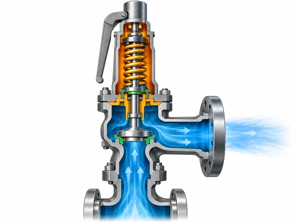
Review how multiple boiler safety valves are staged by set pressure and how documented capacity, protected location, and verification data affect capacity allocation.

Boiler safety valve set pressure staging should not be based on opening order alone. Multiple boiler safety valves should not be staged by set pressure and then checked only by adding nominal capacities. The review has to start with the boiler’s governing pressure basis and required steam-relieving duty, then apply the permitted set-pressure arrangement and credit each valve only on a documented or certified capacity basis that is valid for that valve, its set pressure, steam condition, and protected location.
That distinction matters because set-pressure staging and capacity allocation are related, but they do different jobs. Staging defines part of the pressure-protection arrangement. Capacity allocation determines how the required relieving duty is actually covered. A convincing list of set pressures does not prove sufficient capacity, and a large arithmetic sum of catalog capacities does not prove that the individual contributions are valid for the installed arrangement.
Boiler Safety Valve Set Pressure and Capacity Basis
Before assigning percentages or capacity shares to individual valves, define what the complete protection system is expected to accomplish.
For a steam boiler, that normally means identifying the protected boiler or boiler section, the pressure basis used for protection, the maximum steam-relieving duty that must be accommodated, and the code or project rules that control the arrangement. Those inputs belong at the top of the review because every later decision depends on them.
The pressure fields also need to remain distinct. Normal operating pressure is not the same quantity as maximum allowable working pressure or another governing design limit. Set pressure is not relieving pressure. And none of those pressures is, by itself, a relieving-capacity value.
The same separation applies on the capacity side. The boiler has a required relieving duty. Each valve has a documented or certified capacity under defined conditions. The engineering task is to demonstrate that the capacities that are legitimately creditable in the installed arrangement satisfy the governing boiler requirement.
A useful starting record therefore contains, at minimum:
- the boiler or protected section;
- the applicable code, adopted edition, jurisdiction, or project basis where known;
- the governing pressure or MAWP;
- the normal operating pressure where relevant to the review;
- the required steam-relieving or maximum steam-generating duty used by the design;
- the location of each safety valve;
- the identification of the documentation used to support each valve’s set pressure and capacity.
This order prevents a common mistake: starting with the valves that happen to be available and trying to make their catalog capacities fit a required duty that has not yet been clearly established.
Required duty is not normal steam flow
A boiler may spend most of its operating life below its maximum steam-generating condition. That does not make the normal operating flow the automatic basis for overpressure protection.
The required relieving duty has to come from the governing boiler design and code basis. Depending on the applicable rules, that basis may be tied to maximum steam-generating or evaporative capacity, heat input, or another approved method. No single method should be treated as a universal formula because the governing code and boiler construction have not been fixed for every reader.
The practical rule is simpler: establish the required duty first, then compare the safety-valve arrangement against it.
Stage Set Pressures Without Treating Opening Order as Capacity Proof
When several safety valves protect the same boiler system, assigning them different set pressures can create an intentional staged response. The lower-set valve is positioned to respond at a lower pressure threshold, while additional valves may have higher permitted settings.
But a staged list of nameplate settings is only one part of the pressure-protection design.
The permitted relationship among the settings is code-dependent. For example, current Virginia and Maryland rules for existing power boilers illustrate one U.S. jurisdictional approach: one or more safety valves are set at or below MAWP, additional valves may be set within a limited percentage above MAWP, and the overall range of settings is also limited. Those same rules apply a defined pressure-rise criterion when evaluating whether the installed relieving capacity is sufficient.
Those figures are useful for understanding the engineering pattern, but they are not universal design defaults. Another jurisdiction, a different boiler category, or a different adopted edition may impose a different requirement. The schedule therefore needs a field for the governing source rather than a hard-coded “standard staging percentage.”
There is a second reason not to over-interpret the nameplate settings: two values on a schedule do not, by themselves, prove the exact dynamic sequence in every operating transient. Actual valve behavior also depends on the valve design, setting tolerance, pressure development, installation, and system response.
For the purposes of a boiler safety-valve schedule, the safer interpretation is:
Set pressure defines the intended pressure threshold and must satisfy the governing pressure rules. It does not independently demonstrate how much steam the valve can relieve or prove the adequacy of the complete arrangement.
This is where pressure staging and capacity allocation begin to interact. Changing the set pressure can also change the relieving-pressure basis under which a steam capacity is established. A capacity number should therefore not be detached from the setting and certification basis that supports it.
Allocate Capacity Valve by Valve on the Correct Basis
Once the boiler’s required duty and the permitted set-pressure arrangement are defined, the engineer can turn to the capacity allocated to each valve.
The first question is not “What percentage should each valve carry?” It is:
What capacity can this particular valve legitimately contribute to this particular protected arrangement?
That contribution needs an identifiable basis.
For steam safety valves, recognized certification data can tie relieving capacity to factors such as the valve design identity, marked set pressure or valid set-pressure range, code designator, steam condition, effective flow area, and the relieving-pressure basis used for certification. National Board NB-18 documentation is a useful example of why capacity is not a free-standing catalog value: the certified steam-capacity methodology explicitly relates capacity to marked set pressure, relieving pressure, code basis, and steam condition.
This creates an important review sequence:
- establish the required boiler relieving duty;
- identify each valve;
- подтвердите настроенное давление клапана;
- определите применимый документ по пропускной способности или основание сертификации;
- подтвердите, что документированная пропускная способность относится к соответствующим условиям по пару и давлению;
- определите, можно ли зачесть эту пропускную способность в месте установки;
- только после этого суммируйте допустимые вклады.
Арифметика пропускной способности — это не доказательство пропускной способности
Предположим, в графике указаны три клапана с тремя значениями пропускной способности. Сложить эти три числа математически легко. Инженерный вопрос в том, являются ли эти три числа сопоставимыми и зачитываемыми.
Пропускную способность клапана, взятую при другом настроенном давлении, для другой сертифицированной конструкции или при других условиях по пару, нельзя автоматически переносить в текущий график. Та же осторожность применима, когда число берется из общей таблицы семейства продукции, а не из документации для фактической конструкции клапана.
Это различие можно сформулировать так:
| Позиция графика | Что это может установить | Что оно само по себе не устанавливает |
|---|---|---|
| Давление настройки | Заданное давление настройки клапана | Пропускная способность для сброса |
| Размер присоединения вход/выход | Идентификация физического присоединения | Проходное сечение или сертифицированная пропускная способность |
| Обозначение orifice или проходного сечения | Идентификация части проточной части, где применимо | Сертифицированная пропускная способность при всех условиях |
| Запись о калибровке давления настройки | Подтверждение настройки/статуса испытаний | Требуемая паропроизводительность котла или сертифицированная пропускная способность |
| Запись о сертифицированной/документированной пропускной способности | Пропускная способность на заявленном базисе и условиях | Пригодность для любой установки или проекта |
| Арифметическая сумма нескольких пропускных способностей | Numerical total | Whether all contributions may legally and technically be credited |
That is why “two valves at 50% each” or “three valves sharing the duty equally” should never be the starting assumption unless the governing design and verified valve data support that allocation.
Unequal allocations can also be technically plausible in a multi-valve arrangement, but they should not be treated as a universal rule. The acceptable distribution depends on the governing boiler requirements and on which individual valve capacities can actually be credited.
Calibration and capacity certification are different evidence
A valve can have a valid set-pressure test record without that record proving that the valve provides the steam capacity required by the boiler.
Set-pressure testing answers a setting or operational-test question. Capacity certification answers a flow-performance question under a defined certification basis. A complete boiler schedule often needs both kinds of evidence, but they are not interchangeable.
This distinction becomes especially important during maintenance and replacement. Restoring a valve to the same nominal set pressure does not automatically demonstrate that a replacement valve has the same certified capacity, the same flow area, the same applicable code designator, or the same suitability for the protected location.
When Valve Location Changes What Capacity Can Be Credited
A second major error is to treat every safety valve physically associated with a boiler as though all capacity were available in one unrestricted pool.
That assumption may fail when different valves protect different parts of the boiler.
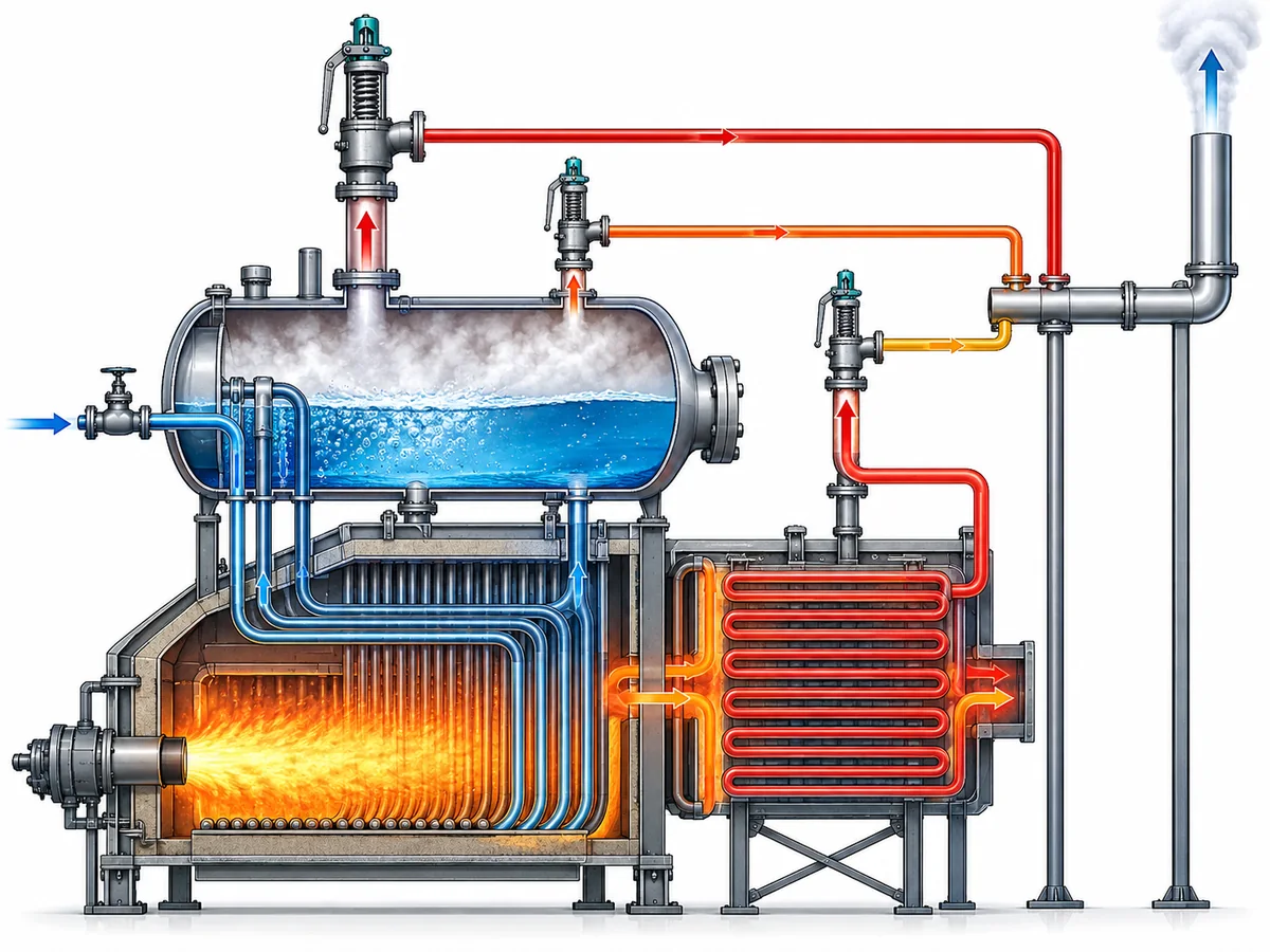
A drum-mounted valve and a valve protecting a superheater, for example, can have different pressure or capacity responsibilities under the applicable boiler rules. Some regulated boiler frameworks explicitly treat the drum and superheater separately while still relating their capacities to an overall boiler generating-capacity requirement.
The exact allocation rule is not universal, so this article does not assign a generic drum/superheater percentage. Instead, the engineer should ask two questions:
- What total relieving duty must the complete boiler protection arrangement satisfy?
- Does the governing code impose a separate local protection or capacity requirement at this valve’s installed location?
Both questions matter.
A total capacity sum may appear adequate while a specific protected section is inadequately covered. Conversely, a valve that provides essential local protection may be creditable toward the total requirement only under defined conditions.
A representative review scenario
Consider a boiler with two safety valves on the main pressure-containing section and another valve associated with a superheater.
The wrong review method is:
Add all three catalog capacities and compare the result with one boiler capacity number.
The more defensible review is:
- establish the required boiler relieving duty;
- identify which section each valve protects;
- verify the permitted setting relationship for those locations;
- identify the documented capacity basis for each valve;
- determine whether the governing rules allow each capacity to contribute to the overall requirement;
- verify any location-specific minimum or separate protection responsibility;
- then assess the combined schedule.
No numerical values are needed to understand the logic. The purpose of the scenario is to show why location is an engineering variable in capacity allocation, not merely a line in an equipment list.
It also explains why changing the location of a valve—or replacing a valve at one location with a superficially similar device—can require more than checking the flange size and set pressure.
Verify the Final Arrangement With a Valve-by-Valve Schedule
The final review should make the evidence visible valve by valve.
A useful schedule does more than list tags, sizes, and set pressures. It should allow an engineer, inspector, or supplier to trace how each valve contributes to the protection basis and where a conclusion still depends on missing project data.
A practical structure is:
| Review field | What to record |
|---|---|
| Valve ID | Unique tag or existing-valve identifier |
| Protected location | Drum, superheater, or other clearly defined protected section |
| Governing pressure basis | MAWP or other applicable approved basis |
| Давление настройки | Proposed or existing marked setting |
| Required / allocated duty | Portion of the governing duty being checked against this valve, where the design uses an allocation |
| Capacity source | Certified capacity listing, manufacturer documentation, approved calculation, or other applicable basis |
| Capacity conditions | Relevant set pressure, relieving-pressure basis, steam condition, and design identity |
| Credited capacity | Capacity actually accepted for the schedule—not simply a catalog maximum |
| Local protection requirement | Any separate requirement associated with the installed location |
| Code / project basis | Standard, jurisdiction, project specification, or design reference |
| Supporting record | Datasheet, certification record, nameplate information, test/calibration record, or calculation reference |
| Статус | Verified / conditional / confirmation required |
The value of this table is not administrative neatness. It forces the reviewer to distinguish three states:
- Proven. The capacity or pressure setting has an applicable, traceable basis.
- Conditional. The engineering relationship is understood, but final credit depends on a code edition, project rule, operating condition, or product document that still needs confirmation.
- Unresolved. The schedule contains a nominal value, but the evidence needed to rely on it has not been identified.
That distinction is more useful than a table in which every field is filled but the source and applicability of the numbers are unclear.
Recheck the whole relationship after a meaningful change
A boiler safety-valve schedule should not be treated as permanently valid simply because the valves remain physically installed.
If the required steam-generating duty is increased, the required relieving capacity can change. If one valve is replaced, its design identity or documented capacity basis can change. If a set pressure changes, the pressure/capacity relationship may need to be reconfirmed. If a valve moves to another protected location, location-specific credit can change.
The precise regulatory consequence of each modification depends on the governing jurisdiction and project requirements. But from an engineering-review standpoint, any change that alters a basis on which the existing schedule credits protection should trigger a check of that basis.
For a replacement valve, do not reduce the comparison to “same connection and same set pressure.” A defensible review may also need to compare:
- valve design or certified design identity;
- set-pressure range;
- documented steam capacity;
- applicable capacity/certification basis;
- flow-area or orifice identity where relevant;
- protected location;
- installation and back-pressure conditions where they affect applicability;
- code, project, and documentation requirements.
Matching only one or two nominal fields is identification evidence—not proof of full interchangeability.
From a Staged Valve List to a Defensible Protection Schedule
Set-pressure staging and capacity allocation should end in one coordinated engineering record.
The pressure side of that record answers: Are the valve settings permitted for this boiler and pressure basis?
The capacity side answers: Does each credited valve capacity have an applicable technical basis, and does the permitted combination satisfy the required relieving duty?
The location check answers: Is the capacity available where the governing protection requirement needs it?
The documentation check answers: Can each important value be traced to the code, calculation, certification record, manufacturer document, or test record that actually supports it?
When those questions are answered together, a multi-valve schedule becomes more than a list of set points and capacities. It becomes a reviewable protection argument.
If any of those bases are still unknown, they should remain visible as confirmation items rather than being replaced by a generic percentage or assumed catalog value.
Prepare the data before requesting an engineering review
For a project-specific review, provide the boiler type and protected sections, applicable code or jurisdiction if known, MAWP or other governing pressure basis, normal operating pressure, required steam-relieving duty or calculation basis, each valve location and set pressure, and the documentation supporting each valve’s capacity.
For an existing installation or replacement, also provide the available valve nameplate, datasheet, certification/capacity records, and information about any boiler-duty or configuration change.
The objective is not to choose a valve from the article alone. It is to give the responsible engineer and valve supplier enough information to determine whether the proposed settings and capacities form one coherent, defensible protection arrangement.