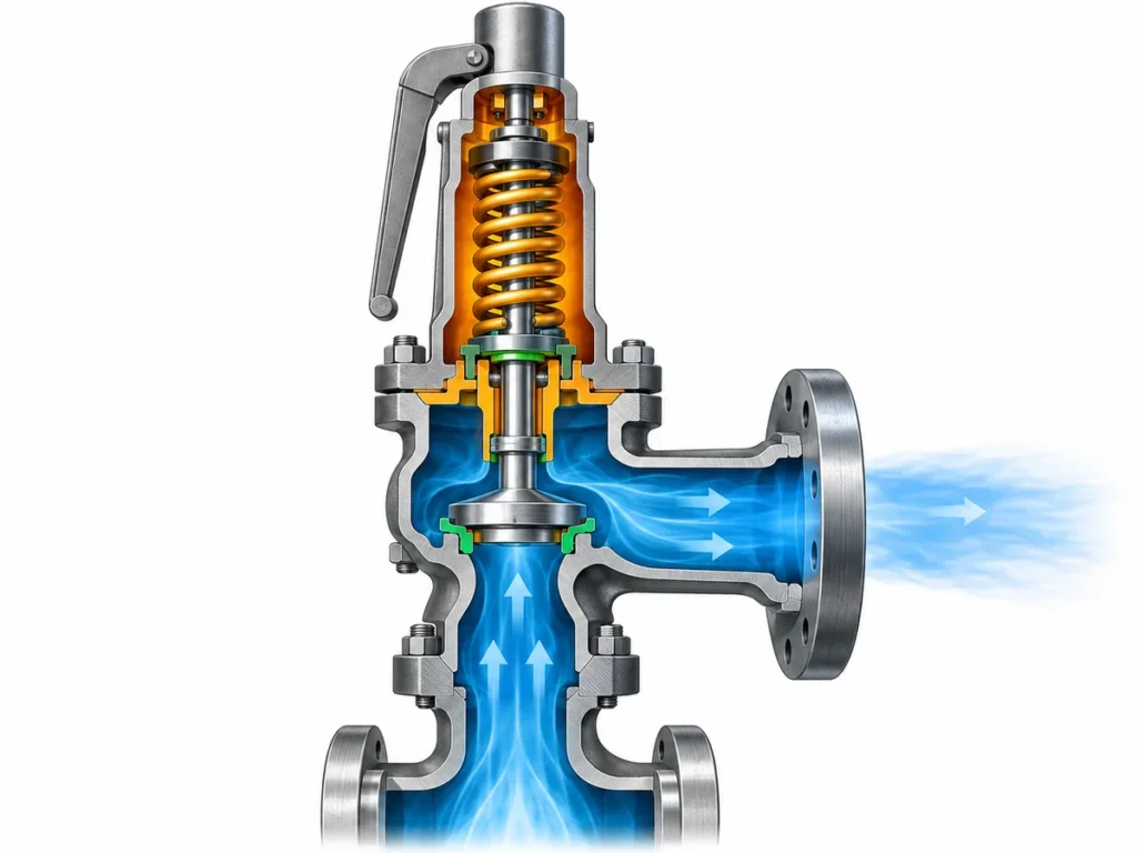
راجع كيفية ترتيب صمامات أمان الغلاية المتعددة حسب ضغط الضبط وكيف تؤثر السعة الموثقة والموقع المحمي وبيانات التحقق في توزيع السعة.

لا ينبغي أن يعتمد ترتيب ضغط ضبط صمامات أمان الغلاية على ترتيب الفتح وحده. لا ينبغي ترتيب صمامات أمان الغلاية المتعددة حسب ضغط الضبط ثم التحقق منها فقط بجمع السعات الاسمية. يجب أن تبدأ المراجعة من أساس الضغط الحاكم للغلاية وواجب تنفيس البخار المطلوب، ثم تطبيق ترتيب ضغط الضبط المسموح به واحتساب كل صمام فقط على أساس سعة موثقة أو معتمدة صالحة لذلك الصمام وضغط ضبطه وظروف البخار والموقع المحمي.
هذا التمييز مهم لأن ترتيب ضغط الضبط وتوزيع السعة مترابطان، لكنهما يؤديان وظيفتين مختلفتين. يحدد الترتيب جزءًا من ترتيب حماية الضغط. أما توزيع السعة فيحدد كيفية تغطية واجب التنفيس المطلوب فعليًا. قائمة مقنعة من ضغوط الضبط لا تثبت كفاية السعة، والمجموع الحسابي الكبير لسعات الكتالوج لا يثبت أن المساهمات الفردية صالحة للترتيب المركب.
أساس ضغط الضبط والسعة لصمامات أمان الغلاية
قبل تخصيص النسب أو حصص السعة للصمامات الفردية، حدد ما يُتوقع من نظام الحماية الكامل تحقيقه.
بالنسبة لغلاية بخارية، يعني ذلك عادةً تحديد الغلاية أو قسم الغلاية المحمي، وأساس الضغط المستخدم للحماية، وأقصى واجب لتنفيس البخار يجب استيعابه، وقواعد الكود أو المشروع التي تحكم الترتيب. تنتمي هذه المدخلات إلى أعلى المراجعة لأن كل قرار لاحق يعتمد عليها.
يجب أيضًا أن تبقى حقول الضغط متمايزة. ضغط التشغيل الطبيعي ليس نفس الكمية مثل الحد الأقصى لضغط العمل المسموح به أو أي حد تصميمي حاكم آخر. ضغط الضبط ليس ضغط التنفيس. ولا أي من هذه الضغوط هو بحد ذاته قيمة سعة تنفيس.
ينطبق نفس الفصل على جانب السعة. لدى الغلاية معدل التصريف المطلوب. لكل صمام السعة الموثقة أو المعتمدة تحت ظروف محددة. تتمثل المهمة الهندسية في إثبات أن السعات المعتبرة بشكل مشروع في التركيب المُنفَّذ تلبي متطلبات الغلاية الحاكمة.
لذلك، يحتوي سجل البداية المفيد، كحد أدنى، على:
- الغلاية أو القسم المحمي؛;
- الكود المعمول به، والطبعة المعتمدة، والاختصاص القضائي، أو أساس المشروع حيثما كان معروفًا؛;
- الضغط الحاكم أو MAWP؛;
- ضغط التشغيل الطبيعي حيثما كان ذا صلة بالمراجعة؛;
- واجب تنفيس البخار المطلوب أو أقصى معدل توليد بخار مستخدم في التصميم؛;
- موقع كل صمام أمان؛;
- تحديد الوثائق المستخدمة لدعم ضغط الضبط والسعة لكل صمام.
يمنع هذا الترتيب خطأً شائعًا: البدء بالصمامات المتاحة فعليًا ومحاولة مطابقة سعاتها من الكتالوج مع واجب مطلوب لم يُحدَّد بوضوح بعد.
الواجب المطلوب ليس معدل تدفق البخار الطبيعي
قد تقضي الغلاية معظم عمرها التشغيلي دون حالة توليد البخار القصوى. وهذا لا يجعل معدل التدفق التشغيلي العادي الأساس التلقائي لحماية الضغط الزائد.
يجب أن تُستمد واجب التنفيس المطلوب من تصميم الغلاية الحاكم والأساس الكودي. ووفقًا للقواعد المعمول بها، قد يرتبط هذا الأساس بأقصى قدرة على توليد البخار أو التبخير، أو مدخلات الحرارة، أو طريقة معتمدة أخرى. ولا ينبغي التعامل مع أي طريقة بمفردها كصيغة عالمية، لأن الكود الحاكم وبناء الغلاية لم يُثبَّتا لكل قارئ.
القاعدة العملية أبسط: حدِّد الواجب المطلوب أولًا، ثم قارن ترتيب صمام الأمان به.
ضبط ضغوط المراحل دون التعامل مع ترتيب الفتح كإثبات للسعة
عندما تحمي عدة صمامات أمان نظام الغلاية نفسه، فإن إسناد ضغوط ضبط مختلفة لها يمكن أن ينشئ استجابة مرحلية مقصودة. ويُوضع الصمام ذو الضبط الأدنى للاستجابة عند عتبة ضغط أقل، بينما قد تكون للصمامات الإضافية إعدادات مسموح بها أعلى.
لكن قائمة المراحل من إعدادات اللوحة المعدنية ليست سوى جزء واحد من تصميم حماية الضغط.
العلاقة المسموح بها بين الإعدادات تعتمد على الكود. فعلى سبيل المثال، توضح القواعد الحالية في فرجينيا وميريلاند لغلايات الطاقة القائمة نهجًا قضائيًا أمريكيًا واحدًا: يُضبط صمام أمان واحد أو أكثر عند MAWP أو أقل منه، ويمكن ضبط صمامات إضافية ضمن نسبة مئوية محدودة فوق MAWP، كما أن النطاق الإجمالي للإعدادات محدود أيضًا. وتطبّق هذه القواعد نفسها معيار ارتفاع ضغط محدد عند تقييم ما إذا كانت سعة التنفيس المركّبة كافية.
هذه الأرقام مفيدة لفهم النمط الهندسي، لكنها ليست إعدادات تصميم عالمية. فقد تفرض ولاية قضائية أخرى، أو فئة غلاية مختلفة، أو إصدار معتمد مختلف متطلبًا مختلفًا. ولذلك يحتاج الجدول إلى حقل للمصدر الحاكم بدلًا من “نسبة المراحل القياسية” المثبتة برمجيًا.”
هناك سبب ثانٍ لعدم المبالغة في تفسير إعدادات لوحة البيانات: فوجود قيمتين في جدول لا يثبت بحد ذاته التسلسل الديناميكي الدقيق في كل حالة تشغيل عابرة. يعتمد سلوك الصمام الفعلي أيضًا على تصميم الصمام، وتفاوت الضبط، وتطور الضغط، والتركيب، واستجابة النظام.
لأغراض جدول صمامات أمان الغلاية، يكون التفسير الأكثر أمانًا هو:
يحدد ضغط الضبط حد الضغط المقصود ويجب أن يستوفي قواعد الضغط الحاكمة. وهو لا يثبت بشكل مستقل مقدار البخار الذي يمكن للصمام تصريفه ولا يثبت كفاية الترتيب الكامل.
هنا يبدأ تفاعل مراحل الضغط وتوزيع السعة. فتغيير ضغط الضبط قد يغيّر أيضًا أساس ضغط التنفيس الذي تُحدد عليه سعة البخار. لذلك لا ينبغي فصل رقم السعة عن أساس الضبط والاعتماد الذي يدعمه.
توزيع السعة صمامًا بصمام على الأساس الصحيح
بعد تحديد الواجب المطلوب للغلاية وترتيب ضغط الضبط المسموح به، يمكن للمهندس الانتقال إلى السعة المخصصة لكل صمام.
السؤال الأول ليس “ما النسبة المئوية التي يجب أن يحملها كل صمام؟” بل:
ما السعة التي يمكن لهذا الصمام تحديدًا أن يساهم بها بشكل مشروع في هذا الترتيب المحمي تحديدًا؟
يحتاج هذا الإسهام إلى أساس قابل للتحديد.
بالنسبة لصمامات أمان البخار، يمكن لبيانات الاعتماد المعترف بها ربط سعة التنفيس بعوامل مثل هوية تصميم الصمام، وضغط الضبط المعلَّم أو نطاق ضغط الضبط الصالح، ورمز الكود، وحالة البخار، ومساحة التدفق الفعلية، وأساس ضغط التنفيس المستخدم للاعتماد. وتُعد وثائق National Board NB-18 مثالًا مفيدًا على أن السعة ليست قيمة كتالوجية قائمة بذاتها: فمنهجية سعة البخار المعتمدة تربط السعة صراحةً بضغط الضبط المعلَّم، وضغط التنفيس، وأساس الكود، وحالة البخار.
وهذا ينشئ تسلسل مراجعة مهمًا:
- تحديد واجب التنفيس المطلوب للغلاية؛;
- identify each valve;
- confirm the valve’s set pressure;
- identify the applicable capacity document or certification basis;
- confirm that the documented capacity applies to the relevant steam and pressure conditions;
- determine whether that capacity is creditable in the installed location;
- only then aggregate the allowed contributions.
Capacity arithmetic is not capacity proof
Suppose a schedule contains three valves with three capacity values. Adding the three numbers is mathematically easy. The engineering question is whether the three numbers are comparable and creditable.
A valve capacity taken from a different set-pressure condition, a different certified design, or a different steam condition cannot automatically be carried into the current schedule. The same caution applies when a number comes from a broad product-family table rather than documentation for the actual valve design.
The distinction can be summarized this way:
| Schedule item | ما يمكنه تأسيسه | ما لا يحدده بحد ذاته |
|---|---|---|
| ضغط الضبط | Intended pressure setting for the valve | سعة التنفيس |
| حجم وصلة المدخل / المخرج | Physical interface identity | Flow area or certified capacity |
| Orifice or flow-area designation | Part of flow-path identity where applicable | Certified capacity under every condition |
| سجل معايرة ضغط الضبط | Evidence about setting/test status | Required boiler duty or certified capacity |
| Certified/documented capacity record | Capacity under its stated basis and conditions | Suitability for every installation or project |
| Arithmetic sum of several capacities | Numerical total | Whether all contributions may legally and technically be credited |
That is why “two valves at 50% each” or “three valves sharing the duty equally” should never be the starting assumption unless the governing design and verified valve data support that allocation.
Unequal allocations can also be technically plausible in a multi-valve arrangement, but they should not be treated as a universal rule. The acceptable distribution depends on the governing boiler requirements and on which individual valve capacities can actually be credited.
Calibration and capacity certification are different evidence
A valve can have a valid set-pressure test record without that record proving that the valve provides the steam capacity required by the boiler.
Set-pressure testing answers a setting or operational-test question. Capacity certification answers a flow-performance question under a defined certification basis. A complete boiler schedule often needs both kinds of evidence, but they are not interchangeable.
This distinction becomes especially important during maintenance and replacement. Restoring a valve to the same nominal set pressure does not automatically demonstrate that a replacement valve has the same certified capacity, the same flow area, the same applicable code designator, or the same suitability for the protected location.
When Valve Location Changes What Capacity Can Be Credited
A second major error is to treat every safety valve physically associated with a boiler as though all capacity were available in one unrestricted pool.
That assumption may fail when different valves protect different parts of the boiler.
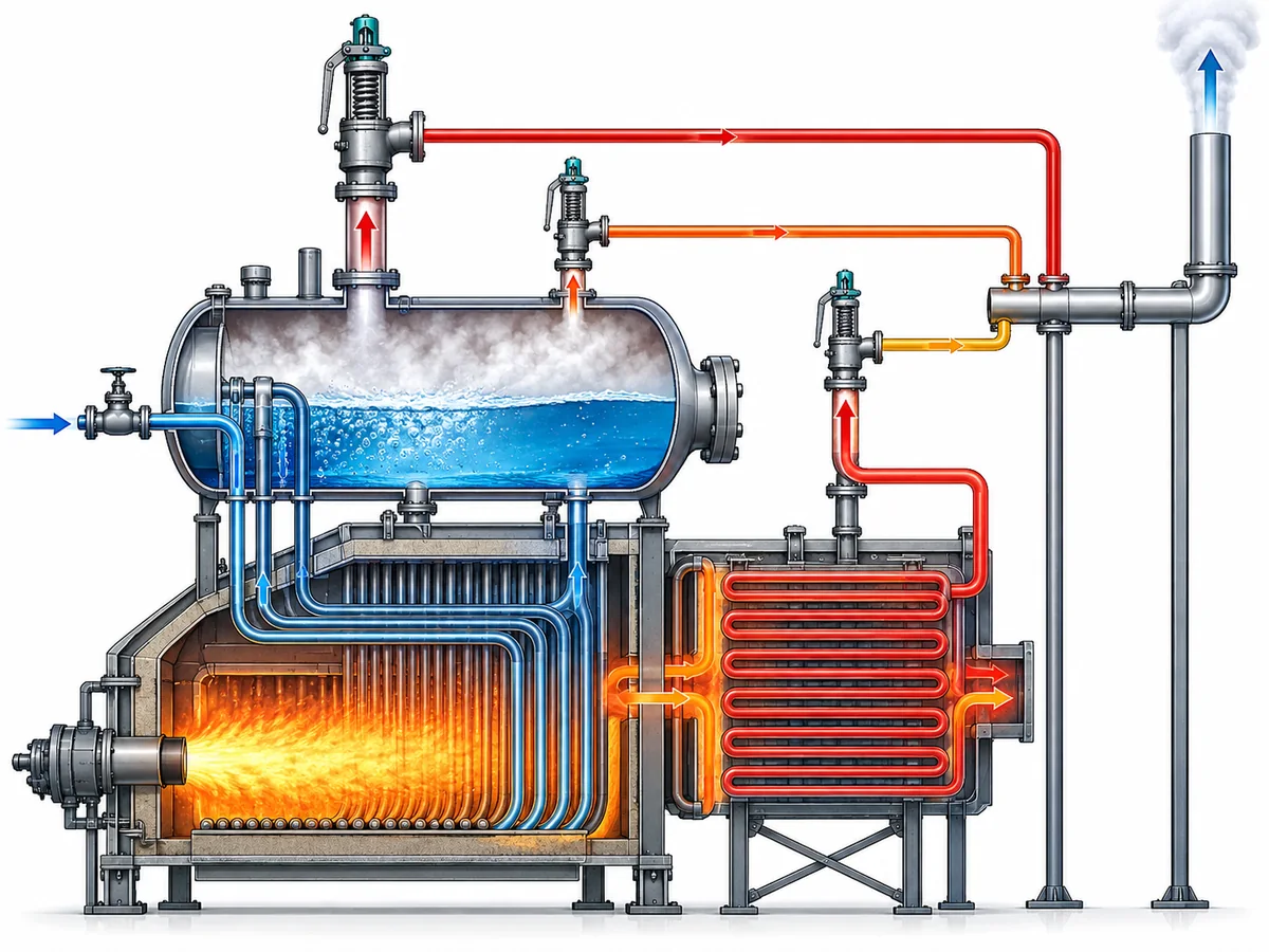
A drum-mounted valve and a valve protecting a superheater, for example, can have different pressure or capacity responsibilities under the applicable boiler rules. Some regulated boiler frameworks explicitly treat the drum and superheater separately while still relating their capacities to an overall boiler generating-capacity requirement.
The exact allocation rule is not universal, so this article does not assign a generic drum/superheater percentage. Instead, the engineer should ask two questions:
- What total relieving duty must the complete boiler protection arrangement satisfy?
- Does the governing code impose a separate local protection or capacity requirement at this valve’s installed location?
Both questions matter.
A total capacity sum may appear adequate while a specific protected section is inadequately covered. Conversely, a valve that provides essential local protection may be creditable toward the total requirement only under defined conditions.
A representative review scenario
Consider a boiler with two safety valves on the main pressure-containing section and another valve associated with a superheater.
The wrong review method is:
Add all three catalog capacities and compare the result with one boiler capacity number.
The more defensible review is:
- تحديد واجب التنفيس المطلوب للغلاية؛;
- identify which section each valve protects;
- verify the permitted setting relationship for those locations;
- identify the documented capacity basis for each valve;
- determine whether the governing rules allow each capacity to contribute to the overall requirement;
- verify any location-specific minimum or separate protection responsibility;
- then assess the combined schedule.
No numerical values are needed to understand the logic. The purpose of the scenario is to show why location is an engineering variable in capacity allocation, not merely a line in an equipment list.
It also explains why changing the location of a valve—or replacing a valve at one location with a superficially similar device—can require more than checking the flange size and set pressure.
Verify the Final Arrangement With a Valve-by-Valve Schedule
The final review should make the evidence visible valve by valve.
A useful schedule does more than list tags, sizes, and set pressures. It should allow an engineer, inspector, or supplier to trace how each valve contributes to the protection basis and where a conclusion still depends on missing project data.
A practical structure is:
| Review field | What to record |
|---|---|
| Valve ID | Unique tag or existing-valve identifier |
| Protected location | Drum, superheater, or other clearly defined protected section |
| Governing pressure basis | MAWP or other applicable approved basis |
| ضغط الضبط | Proposed or existing marked setting |
| Required / allocated duty | Portion of the governing duty being checked against this valve, where the design uses an allocation |
| Capacity source | Certified capacity listing, manufacturer documentation, approved calculation, or other applicable basis |
| Capacity conditions | Relevant set pressure, relieving-pressure basis, steam condition, and design identity |
| Credited capacity | Capacity actually accepted for the schedule—not simply a catalog maximum |
| Local protection requirement | Any separate requirement associated with the installed location |
| Code / project basis | Standard, jurisdiction, project specification, or design reference |
| Supporting record | Datasheet, certification record, nameplate information, test/calibration record, or calculation reference |
| الحالة | Verified / conditional / confirmation required |
The value of this table is not administrative neatness. It forces the reviewer to distinguish three states:
- Proven. The capacity or pressure setting has an applicable, traceable basis.
- Conditional. The engineering relationship is understood, but final credit depends on a code edition, project rule, operating condition, or product document that still needs confirmation.
- Unresolved. The schedule contains a nominal value, but the evidence needed to rely on it has not been identified.
That distinction is more useful than a table in which every field is filled but the source and applicability of the numbers are unclear.
Recheck the whole relationship after a meaningful change
A boiler safety-valve schedule should not be treated as permanently valid simply because the valves remain physically installed.
If the required steam-generating duty is increased, the required relieving capacity can change. If one valve is replaced, its design identity or documented capacity basis can change. If a set pressure changes, the pressure/capacity relationship may need to be reconfirmed. If a valve moves to another protected location, location-specific credit can change.
The precise regulatory consequence of each modification depends on the governing jurisdiction and project requirements. But from an engineering-review standpoint, any change that alters a basis on which the existing schedule credits protection should trigger a check of that basis.
For a replacement valve, do not reduce the comparison to “same connection and same set pressure.” A defensible review may also need to compare:
- valve design or certified design identity;
- set-pressure range;
- documented steam capacity;
- applicable capacity/certification basis;
- flow-area or orifice identity where relevant;
- protected location;
- installation and back-pressure conditions where they affect applicability;
- code, project, and documentation requirements.
Matching only one or two nominal fields is identification evidence—not proof of full interchangeability.
From a Staged Valve List to a Defensible Protection Schedule
Set-pressure staging and capacity allocation should end in one coordinated engineering record.
The pressure side of that record answers: Are the valve settings permitted for this boiler and pressure basis?
The capacity side answers: Does each credited valve capacity have an applicable technical basis, and does the permitted combination satisfy the required relieving duty?
The location check answers: Is the capacity available where the governing protection requirement needs it?
The documentation check answers: Can each important value be traced to the code, calculation, certification record, manufacturer document, or test record that actually supports it?
When those questions are answered together, a multi-valve schedule becomes more than a list of set points and capacities. It becomes a reviewable protection argument.
If any of those bases are still unknown, they should remain visible as confirmation items rather than being replaced by a generic percentage or assumed catalog value.
Prepare the data before requesting an engineering review
For a project-specific review, provide the boiler type and protected sections, applicable code or jurisdiction if known, MAWP or other governing pressure basis, normal operating pressure, required steam-relieving duty or calculation basis, each valve location and set pressure, and the documentation supporting each valve’s capacity.
For an existing installation or replacement, also provide the available valve nameplate, datasheet, certification/capacity records, and information about any boiler-duty or configuration change.
The objective is not to choose a valve from the article alone. It is to give the responsible engineer and valve supplier enough information to determine whether the proposed settings and capacities form one coherent, defensible protection arrangement.