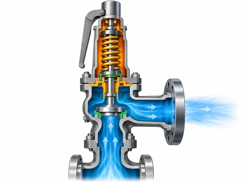
Prüfen Sie, wie mehrere Kessel-Sicherheitsventile nach Ansprechdruck gestaffelt sind und wie dokumentierte Abblaseleistung, geschützter Einbauort und Verifikationsdaten die Kapazitätsaufteilung beeinflussen.

Die Staffelung der Ansprechdrücke von Kessel-Sicherheitsventilen sollte nicht allein auf der Öffnungsreihenfolge basieren. Mehrere Kessel-Sicherheitsventile sollten nicht nach Ansprechdruck gestaffelt und dann nur durch Addition der Nennabblaseleistungen überprüft werden. Die Prüfung muss mit dem maßgeblichen Druckbezug des Kessels und der erforderlichen Dampfabblaseleistung beginnen und dann die zulässige Anordnung der Ansprechdrücke anwenden und jedes Ventil nur auf Basis einer dokumentierten oder zertifizierten Abblaseleistung anrechnen, die für dieses Ventil, seinen Ansprechdruck, seine Dampfbedingungen und seinen geschützten Einbauort gültig ist.
Diese Unterscheidung ist wichtig, weil Ansprechdruck-Staffelung und Kapazitätsaufteilung zusammenhängen, aber unterschiedliche Aufgaben erfüllen. Die Staffelung definiert einen Teil der Druckabsicherung. Die Kapazitätsaufteilung bestimmt, wie die erforderliche Abblaseleistung tatsächlich abgedeckt wird. Eine überzeugende Liste von Ansprechdrücken beweist keine ausreichende Kapazität, und eine große arithmetische Summe von Katalog-Abblaseleistungen beweist nicht, dass die einzelnen Beiträge für die installierte Anordnung gültig sind.
Ansprechdruck und Kapazitätsgrundlage von Kessel-Sicherheitsventilen
Bevor Prozentsätze oder Kapazitätsanteile einzelnen Ventilen zugewiesen werden, muss definiert werden, was das gesamte Schutzsystem leisten soll.
Für einen Dampfkessel bedeutet das normalerweise, den geschützten Kessel oder Kesselabschnitt, den für den Schutz verwendeten Druckbezug, die maximale abzuführende Dampfabblaseleistung und die Code- oder Projektvorschriften, die die Anordnung regeln, zu identifizieren. Diese Eingangsgrößen gehören an den Anfang der Prüfung, da jede spätere Entscheidung von ihnen abhängt.
Auch die Druckfelder müssen getrennt bleiben. Der normale Betriebsdruck ist nicht dieselbe Größe wie der maximal zulässige Betriebsdruck oder eine andere maßgebliche Auslegungsgrenze. Der Ansprechdruck ist nicht der Abblasedruck. Und keiner dieser Drücke ist für sich genommen ein Wert für die Abblaseleistung.
Dieselbe Trennung gilt auf der Kapazitätsseite. Der Kessel hat eine erforderlichen Abblaseleistung. Jedes Ventil hat eine dokumentierte oder zertifizierte Abblaseleistung unter definierten Bedingungen. Die ingenieurtechnische Aufgabe besteht darin, nachzuweisen, dass die im installierten Zustand anrechenbaren Abblaseleistungen die maßgebliche Kesselanforderung erfüllen.
Eine zweckmäßige erste Aufstellung enthält daher mindestens:
- den Kessel oder den geschützten Abschnitt;
- das anzuwendende Regelwerk, die verwendete Ausgabe, die Jurisdiktion oder die Projektgrundlage, soweit bekannt;
- den maßgeblichen Druck oder MAWP;
- den normalen Betriebsdruck, soweit für die Betrachtung relevant;
- die erforderliche Dampfabblaseleistung oder die der Auslegung zugrunde liegende maximale Dampferzeugungsleistung;
- den Einbauort jedes Sicherheitsventils;
- die Angabe der Dokumentation, die zur Belegung von Ansprechdruck und Abblaseleistung jedes Ventils herangezogen wird.
Diese Reihenfolge verhindert einen häufigen Fehler: mit den gerade verfügbaren Ventilen zu beginnen und zu versuchen, deren Katalog-Abblaseleistungen an eine noch nicht eindeutig festgelegte Anforderung anzupassen.
Die erforderliche Abblaseleistung ist nicht der normale Dampfstrom
Ein Kessel kann den größten Teil seiner Betriebslebensdauer unterhalb seiner maximalen Dampferzeugungsleistung betrieben werden. Das macht den normalen Betriebsdurchfluss nicht automatisch zur Grundlage für den Überdruckschutz.
Die erforderliche Abblaseleistung muss sich aus der maßgeblichen Kesselauslegung und der Code-Grundlage ergeben. Je nach den anwendbaren Regeln kann diese Grundlage an die maximale Dampferzeugungs- oder Verdampfungskapazität, die Wärmezufuhr oder eine andere zugelassene Methode gebunden sein. Keine einzelne Methode sollte als universelle Formel betrachtet werden, da der maßgebliche Code und die Kesselbauart nicht für jeden Leser festgelegt sind.
Die praktische Regel ist einfacher: zuerst die erforderliche Abblaseleistung festlegen, dann die Sicherheitsventil-Anordnung damit vergleichen.
Gestufte Ansprechdrücke festlegen, ohne die Öffnungsreihenfolge als Kapazitätsnachweis zu behandeln
Wenn mehrere Sicherheitsventile dasselbe Kesselsystem schützen, kann die Zuweisung unterschiedlicher Ansprechdrücke eine bewusste gestufte Reaktion erzeugen. Das Ventil mit dem niedrigeren Ansprechdruck ist so positioniert, dass es bei einer niedrigeren Druckschwelle anspricht, während zusätzliche Ventile höhere zulässige Einstellungen haben können.
Doch eine gestufte Liste von Typenschild-Einstellungen ist nur ein Teil der Druckentlastungsauslegung.
Die zulässige Beziehung zwischen den Einstellungen ist codeabhängig. Beispielsweise veranschaulichen die aktuellen Vorschriften von Virginia und Maryland für bestehende Kraftwerkskessel einen US-amerikanischen Aufsichtsansatz: Ein oder mehrere Sicherheitsventile sind auf oder unter MAWP eingestellt, zusätzliche Ventile dürfen innerhalb eines begrenzten Prozentsatzes über MAWP eingestellt werden, und der Gesamtbereich der Einstellungen ist ebenfalls begrenzt. Dieselben Vorschriften wenden ein definiertes Druckanstiegskriterium an, wenn beurteilt wird, ob die installierte Abblaseleistung ausreichend ist.
Diese Zahlen sind nützlich, um das technische Muster zu verstehen, aber sie sind keine universellen Auslegungsvorgaben. Eine andere Aufsichtsbehörde, eine andere Kesselkategorie oder eine andere übernommene Ausgabe kann eine andere Anforderung vorschreiben. Der Zeitplan benötigt daher ein Feld für die maßgebliche Quelle anstelle eines fest codierten “Standard-Stufungsprozentsatzes”.”
Es gibt einen zweiten Grund, die Typenschild-Einstellungen nicht zu überinterpretieren: Zwei Werte in einem Datenblatt beweisen für sich genommen nicht die exakte dynamische Abfolge bei jedem Betriebstransienten. Das tatsächliche Ventilverhalten hängt auch von der Ventilkonstruktion, der Einstelltoleranz, der Druckentwicklung, der Installation und der Systemreaktion ab.
Für die Zwecke eines Kesselsicherheitsventil-Datenblatts ist die sicherere Auslegung:
Der Einstelldruck definiert die vorgesehene Druckschwelle und muss die geltenden Druckvorschriften erfüllen. Er belegt jedoch nicht eigenständig, wie viel Dampf das Ventil abblasen kann, und beweist auch nicht die Angemessenheit der gesamten Anordnung.
Hier beginnen Druckstufung und Kapazitätszuordnung zusammenzuwirken. Eine Änderung des Einstelldrucks kann auch die Abblasedruckbasis verändern, auf der eine Dampfkapazität ermittelt wird. Eine Kapazitätsangabe sollte daher nicht von der Einstell- und Zertifizierungsbasis getrennt werden, die sie stützt.
Kapazität Ventil für Ventil auf der richtigen Basis zuordnen
Sobald die erforderliche Kesselleistung und die zulässige Einstelldruckanordnung festgelegt sind, kann sich der Ingenieur der jedem Ventil zugeordneten Kapazität zuwenden.
Die erste Frage lautet nicht: “Welchen Prozentsatz soll jedes Ventil übernehmen?” Sondern:
Welche Kapazität kann dieses spezielle Ventil legitimerweise zu dieser speziellen geschützten Anordnung beitragen?
Dieser Beitrag benötigt eine identifizierbare Grundlage.
Bei Dampf-Sicherheitsventilen können anerkannte Zertifizierungsdaten die Abblaseleistung an Faktoren wie die Ventilkonstruktionsidentität, den markierten Einstelldruck oder gültigen Einstelldruckbereich, die Code-Kennzeichnung, den Dampfzustand, die effektive Durchflussfläche und die zur Zertifizierung verwendete Abblasedruckbasis binden. Die NB-18-Dokumentation des National Board ist ein nützliches Beispiel dafür, warum die Kapazität kein frei stehender Katalogwert ist: Die zertifizierte Dampfkapazitätsmethodik setzt die Kapazität ausdrücklich in Beziehung zum markierten Einstelldruck, zum Abblasedruck, zur Code-Basis und zum Dampfzustand.
Daraus ergibt sich eine wichtige Prüfreihenfolge:
- die erforderliche Kessel-Abblaseleistung festlegen;
- identify each valve;
- confirm the valve’s set pressure;
- identify the applicable capacity document or certification basis;
- confirm that the documented capacity applies to the relevant steam and pressure conditions;
- determine whether that capacity is creditable in the installed location;
- only then aggregate the allowed contributions.
Capacity arithmetic is not capacity proof
Suppose a schedule contains three valves with three capacity values. Adding the three numbers is mathematically easy. The engineering question is whether the three numbers are comparable and creditable.
A valve capacity taken from a different set-pressure condition, a different certified design, or a different steam condition cannot automatically be carried into the current schedule. The same caution applies when a number comes from a broad product-family table rather than documentation for the actual valve design.
The distinction can be summarized this way:
| Schedule item | Was es etablieren kann | Was dadurch allein nicht festgelegt wird |
|---|---|---|
| Ansprechdruck | Intended pressure setting for the valve | Abblaseleistung |
| Einlass-/Auslassanschlussgröße | Physical interface identity | Flow area or certified capacity |
| Orifice or flow-area designation | Part of flow-path identity where applicable | Certified capacity under every condition |
| Aufzeichnungsblatt für die Einstellung des Ansprechdrucks | Evidence about setting/test status | Required boiler duty or certified capacity |
| Certified/documented capacity record | Capacity under its stated basis and conditions | Suitability for every installation or project |
| Arithmetic sum of several capacities | Numerical total | Whether all contributions may legally and technically be credited |
That is why “two valves at 50% each” or “three valves sharing the duty equally” should never be the starting assumption unless the governing design and verified valve data support that allocation.
Unequal allocations can also be technically plausible in a multi-valve arrangement, but they should not be treated as a universal rule. The acceptable distribution depends on the governing boiler requirements and on which individual valve capacities can actually be credited.
Calibration and capacity certification are different evidence
A valve can have a valid set-pressure test record without that record proving that the valve provides the steam capacity required by the boiler.
Set-pressure testing answers a setting or operational-test question. Capacity certification answers a flow-performance question under a defined certification basis. A complete boiler schedule often needs both kinds of evidence, but they are not interchangeable.
This distinction becomes especially important during maintenance and replacement. Restoring a valve to the same nominal set pressure does not automatically demonstrate that a replacement valve has the same certified capacity, the same flow area, the same applicable code designator, or the same suitability for the protected location.
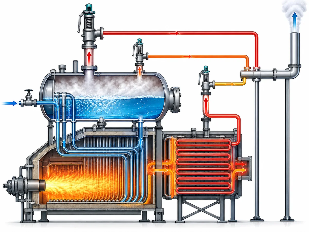
When Valve Location Changes What Capacity Can Be Credited
A second major error is to treat every safety valve physically associated with a boiler as though all capacity were available in one unrestricted pool.
That assumption may fail when different valves protect different parts of the boiler.
A drum-mounted valve and a valve protecting a superheater, for example, can have different pressure or capacity responsibilities under the applicable boiler rules. Some regulated boiler frameworks explicitly treat the drum and superheater separately while still relating their capacities to an overall boiler generating-capacity requirement.
The exact allocation rule is not universal, so this article does not assign a generic drum/superheater percentage. Instead, the engineer should ask two questions:
- What total relieving duty must the complete boiler protection arrangement satisfy?
- Does the governing code impose a separate local protection or capacity requirement at this valve’s installed location?
Both questions matter.
A total capacity sum may appear adequate while a specific protected section is inadequately covered. Conversely, a valve that provides essential local protection may be creditable toward the total requirement only under defined conditions.
A representative review scenario
Consider a boiler with two safety valves on the main pressure-containing section and another valve associated with a superheater.
The wrong review method is:
Add all three catalog capacities and compare the result with one boiler capacity number.
The more defensible review is:
- die erforderliche Kessel-Abblaseleistung festlegen;
- identify which section each valve protects;
- verify the permitted setting relationship for those locations;
- identify the documented capacity basis for each valve;
- determine whether the governing rules allow each capacity to contribute to the overall requirement;
- verify any location-specific minimum or separate protection responsibility;
- then assess the combined schedule.
No numerical values are needed to understand the logic. The purpose of the scenario is to show why location is an engineering variable in capacity allocation, not merely a line in an equipment list.
It also explains why changing the location of a valve—or replacing a valve at one location with a superficially similar device—can require more than checking the flange size and set pressure.
Verify the Final Arrangement With a Valve-by-Valve Schedule
The final review should make the evidence visible valve by valve.
A useful schedule does more than list tags, sizes, and set pressures. It should allow an engineer, inspector, or supplier to trace how each valve contributes to the protection basis and where a conclusion still depends on missing project data.
A practical structure is:
| Review field | Was aufgezeichnet werden sollte |
|---|---|
| Valve ID | Unique tag or existing-valve identifier |
| Protected location | Drum, superheater, or other clearly defined protected section |
| Governing pressure basis | MAWP or other applicable approved basis |
| Ansprechdruck | Proposed or existing marked setting |
| Required / allocated duty | Portion of the governing duty being checked against this valve, where the design uses an allocation |
| Capacity source | Certified capacity listing, manufacturer documentation, approved calculation, or other applicable basis |
| Capacity conditions | Relevant set pressure, relieving-pressure basis, steam condition, and design identity |
| Credited capacity | Capacity actually accepted for the schedule—not simply a catalog maximum |
| Local protection requirement | Any separate requirement associated with the installed location |
| Code / project basis | Standard, jurisdiction, project specification, or design reference |
| Supporting record | Datasheet, certification record, nameplate information, test/calibration record, or calculation reference |
| Status | Verified / conditional / confirmation required |
The value of this table is not administrative neatness. It forces the reviewer to distinguish three states:
- Proven. The capacity or pressure setting has an applicable, traceable basis.
- Conditional. The engineering relationship is understood, but final credit depends on a code edition, project rule, operating condition, or product document that still needs confirmation.
- Unresolved. The schedule contains a nominal value, but the evidence needed to rely on it has not been identified.
That distinction is more useful than a table in which every field is filled but the source and applicability of the numbers are unclear.
Recheck the whole relationship after a meaningful change
A boiler safety-valve schedule should not be treated as permanently valid simply because the valves remain physically installed.
If the required steam-generating duty is increased, the required relieving capacity can change. If one valve is replaced, its design identity or documented capacity basis can change. If a set pressure changes, the pressure/capacity relationship may need to be reconfirmed. If a valve moves to another protected location, location-specific credit can change.
The precise regulatory consequence of each modification depends on the governing jurisdiction and project requirements. But from an engineering-review standpoint, any change that alters a basis on which the existing schedule credits protection should trigger a check of that basis.
For a replacement valve, do not reduce the comparison to “same connection and same set pressure.” A defensible review may also need to compare:
- valve design or certified design identity;
- set-pressure range;
- documented steam capacity;
- applicable capacity/certification basis;
- flow-area or orifice identity where relevant;
- protected location;
- installation and back-pressure conditions where they affect applicability;
- code, project, and documentation requirements.
Matching only one or two nominal fields is identification evidence—not proof of full interchangeability.
From a Staged Valve List to a Defensible Protection Schedule
Set-pressure staging and capacity allocation should end in one coordinated engineering record.
The pressure side of that record answers: Are the valve settings permitted for this boiler and pressure basis?
The capacity side answers: Does each credited valve capacity have an applicable technical basis, and does the permitted combination satisfy the required relieving duty?
The location check answers: Is the capacity available where the governing protection requirement needs it?
The documentation check answers: Can each important value be traced to the code, calculation, certification record, manufacturer document, or test record that actually supports it?
When those questions are answered together, a multi-valve schedule becomes more than a list of set points and capacities. It becomes a reviewable protection argument.
If any of those bases are still unknown, they should remain visible as confirmation items rather than being replaced by a generic percentage or assumed catalog value.
Prepare the data before requesting an engineering review
For a project-specific review, provide the boiler type and protected sections, applicable code or jurisdiction if known, MAWP or other governing pressure basis, normal operating pressure, required steam-relieving duty or calculation basis, each valve location and set pressure, and the documentation supporting each valve’s capacity.
For an existing installation or replacement, also provide the available valve nameplate, datasheet, certification/capacity records, and information about any boiler-duty or configuration change.
The objective is not to choose a valve from the article alone. It is to give the responsible engineer and valve supplier enough information to determine whether the proposed settings and capacities form one coherent, defensible protection arrangement.