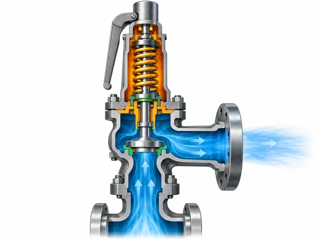
تعرف على كيفية تأثير اللزوجة والتبريد والتصميم المزود بغلاف والسعة والضغط الخلفي والتركيب على اختيار صمام الأمان للبيتومين والأسفلت والزيوت الثقيلة.

لا ينبغي اختيار صمامات الأمان لأنظمة البيتومين والأسفلت والزيوت الثقيلة بالبدء من سؤال “هل أحتاج إلى صمام مزود بغلاف؟”. المهمة الأولى هي تحديد سيناريو التنفيس الفعلي، وحالة المائع عند ظروف التنفيس، وما إذا كان المسار الكامل من المعدة المحمية عبر الصمام قادرًا على البقاء قادرًا على التنفيس. يمكن أن يكون التصميم المزود بغلاف إجراءً مهمًا للإدارة الحرارية، لكنه لا يحل محل حساب المقاسات أو التحقق من السعة أو مراجعة الضغط الخلفي أو اختيار المواد أو هندسة التركيب.
هذا التمييز مهم لأن البيتومين والأسفلت والزيوت الثقيلة خدمات شديدة الحساسية لدرجة الحرارة. مع انخفاض درجة الحرارة، قد ترتفع اللزوجة بشكل حاد، وقد تتصلب بعض المنتجات أو تترسب أو تصبح صعبة الحركة. يعتمد السلوك الدقيق على الدرجة والتركيب والتاريخ التشغيلي؛ لا توجد لزوجة واحدة أو “درجة حرارة تصلب” يمكنها تمثيل كل خدمة أسفلت أو زيت ثقيل بأمان.
لذلك فإن السؤال الهندسي أوسع من نوع الصمام. إنه ما إذا كان نظام تنفيس الضغط المختار قادرًا على البقاء مفتوحًا وقادرًا على التدفق وبالمقاس الصحيح تحت ظروف التشغيل والاستعداد والتنفيس الفعلية.
صمامات الأمان للبيتومين: ابدأ من حالة المائع
“البيتومين” و“الأسفلت” و“الزيت الثقيل” تسميات خدمة مفيدة، لكنها لا تحدد واجب صمام التنفيس.
يمكن أن يتصرف تياران من الزيوت الثقيلة بشكل مختلف جدًا عند نفس درجة الحرارة الاسمية. وبالمثل، قد تظل درجة أسفلت واحدة تتدفق بسهولة عند درجة حرارة تصبح فيها أخرى أكثر مقاومة للحركة. قد تظهر بعض الزيوت الثقيلة أيضًا سلوكًا غير نيوتوني، لذا قد لا يصف افتراض لزوجة عام واحد حالة التنفيس بدقة.
بالنسبة لاختيار تنفيس الضغط، تكون الأسئلة المفيدة أكثر تحديدًا:
- ما هو المنتج أو الدرجة أو التركيب الدقيق الذي يتم التعامل معه؟
- هل من المتوقع أن يكون مائع التنفيس سائلًا أو بخارًا أو خليطًا غازيًا سائلًا أو حالة طورية أخرى؟
- ما هي درجات حرارة التشغيل والتنفيس العادية؟
- What temperatures can occur during startup, shutdown or prolonged standby?
- Is viscosity-versus-temperature information available for the actual process fluid?
- Is there evidence of hardening, wax formation, deposition, coking, crystallization or other restriction mechanisms in this service?
The answers affect more than the choice between a standard and a jacketed valve. They can change the sizing basis, the likelihood of restriction in the inlet or valve flow path, the material and seat review, and the amount of thermal management that the installed system may need.
This is also where terminology matters. Searches for an “asphalt relief valve” often surface internal pump bypass or relief devices. Those devices can protect a pump against excessive differential pressure, but they are not automatically equivalent to a pressure safety valve or pressure relief valve protecting a vessel, pipeline or other pressure system. The protection duty must be identified before the valve can be selected.
Follow the complete relief path for cooling, restriction and deposit risk
A pressure-relief valve only protects the equipment if pressure from the protected system can reach the valve and the required relieving flow can pass through the device and discharge path.
That makes the complete relief path important in temperature-sensitive service.
A useful review normally starts at the equipment nozzle or branch and follows the path through:
- the protected-equipment connection;
- the inlet piping and any restrictions;
- the valve inlet and internal flow passage;
- the valve outlet; and
- the downstream discharge arrangement where the process medium can enter or influence it.
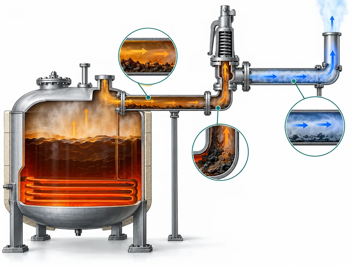
The purpose is not to assume that every part of the system must be steam traced or jacketed. It is to identify where cooling, stagnant material, deposits or geometric restrictions could become relevant to the particular installation.
Consider a representative heated asphalt vessel with a safety valve connected through a short process branch. During normal operation the vessel contents may be maintained at a temperature that keeps the material readily flowable. That does not automatically mean the branch and valve remain at the same condition during a long standby period. If an unheated section cools substantially, the material present there may become much more viscous or may form deposits.
The engineering consequence is not simply “add heat tracing.” The correct sequence is to determine whether the condition is credible, where it can occur, and whether it could restrict pressure communication or relieving flow. Only then can the project decide whether insulation, tracing, a valve jacket, a different arrangement, operating procedures or another measure is appropriate.
The same discipline applies downstream. Some services may require a review of cooling, drainage or accumulation in the discharge system, but that does not support a universal rule that every heavy-oil safety-valve outlet must be heated. The actual discharge destination, piping geometry, back pressure and process-fluid exposure determine what needs to be checked.
Decide when jacketed construction belongs in the solution—and what it cannot solve
A صمام أمان مزود بغلاف provides a way to transfer heat to a defined region of the valve body or associated valve structure. For viscous, sticky, crystallizing or solidification-prone media, this can help maintain a more favorable fluid condition in the portion of the relief path covered by the jacket.
That is a legitimate engineering function, but its boundary should be clear.
A jacket normally heats the region designed into the valve. It does not automatically maintain the temperature of the vessel nozzle, upstream branch, inlet piping or discharge piping. If those areas are also vulnerable to cooling or deposits, their thermal condition has to be reviewed separately.
The most useful selection question is therefore not:
Is this a heavy-oil service?
بل هو:
Which parts of the relief path are at risk of losing the fluid condition required for reliable pressure communication and flow, and what thermal-management measures are justified at those locations?
A jacketed valve becomes a stronger candidate when the evidence shows that maintaining temperature around the valve flow path is important. The exact jacket arrangement, however, is product-specific. Jacket coverage, utility connections, allowable utility conditions and the type of heating medium cannot be inferred from the word “jacketed” alone.
Heating media can also differ between designs and projects. Steam may be used in some systems, while other applications may use a different approved heating medium. The allowable pressure and temperature of the jacket circuit must come from the exact manufacturer data and project design basis.
There is another practical distinction: heating and flushing are different functions. Some jacketed-valve designs may incorporate auxiliary connections intended for specific maintenance or flushing arrangements, but their presence and purpose must be confirmed from the exact drawing. They should not be assumed for every jacketed valve.
ZOBAI’s product catalog includes a ZBNJ jacketed safety-valve family, including cataloged configurations with a jacketed body and auxiliary connections. That confirms the existence of the product family, not the suitability of a particular ZBNJ model for every bitumen, asphalt or heavy-oil duty. Exact pressure and temperature limits, jacket conditions, materials, connections, capacity basis and certification must be confirmed against the selected model and current documentation.
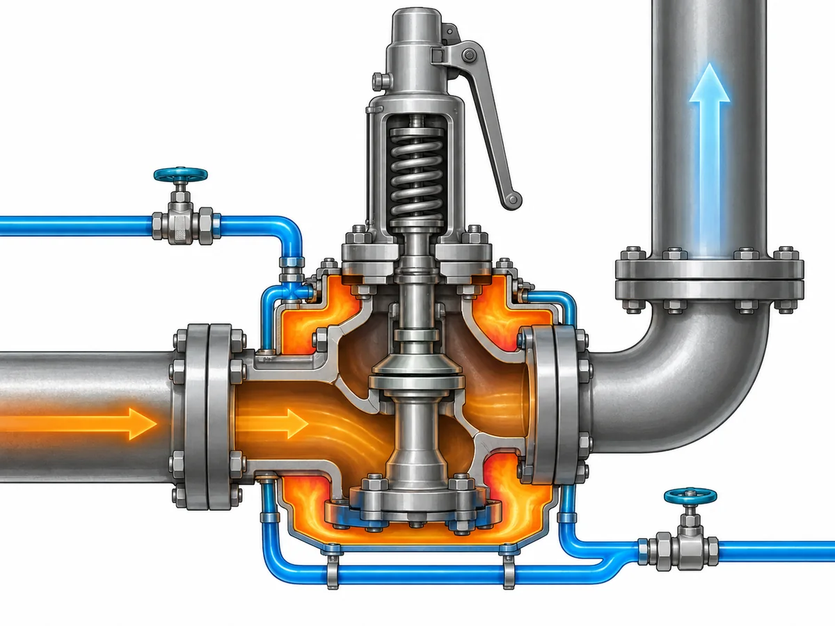
The key boundary is simple: a jacket can address a defined thermal problem; it does not by itself prove that the pressure-relief system is adequately sized or correctly installed.
Keep thermal management separate from sizing, capacity and back pressure
Thermal management answers one question: can the process medium remain in a condition that allows the intended relief path to function?
Pressure-relief sizing answers another: can the selected valve pass the required relieving load under the specified relieving conditions?
Those questions interact, but they are not interchangeable.
For viscous liquid service, actual fluid viscosity can affect the sizing calculation. Recognized pressure-relief sizing methods account for viscosity where applicable rather than treating every liquid as an inviscid fluid. The exact correction method, coefficients and acceptance basis must follow the governing standard, the fluid data and the selected manufacturer’s documented performance basis.
That leads to several distinctions that should remain separate throughout the specification:
| سؤال هندسي | ما الذي يجب إثباته | What does يحدد prove it |
|---|---|---|
| Required relief duty | Governing overpressure scenario and required relieving rate | Valve connection size |
| مساحة التدفق المطلوبة | Applicable sizing method using actual relieving conditions | A jacketed body |
| سعة الصمام | Documented or certified capacity for the exact selected valve and applicable basis | Similar appearance or nominal size |
| Thermal suitability | Fluid behavior and temperature condition through the relevant relief path | Capacity calculation alone |
| Back-pressure suitability | Outlet system and valve configuration under actual back pressure | The word “jacketed” |
| Inlet suitability | Pressure communication, geometry and inlet-loss condition | Matching inlet flange size |
Required relieving capacity is therefore not the same thing as the selected orifice, and neither is automatically the same as the certified or documented capacity of a particular valve. The calculation establishes what the system requires. Product data establish what the exact selected valve can deliver under its applicable performance basis.
The pressure definitions also need to remain distinct. Operating pressure, design pressure or MAWP, set pressure, allowed overpressure or accumulation, and relieving pressure serve different purposes in the relief design. Changing the thermal arrangement does not remove the need to establish those values correctly.
Inlet pressure loss is another independent check. A pressure-relief valve depends on pressure being transmitted from the protected equipment to its inlet without an unacceptable loss that changes its behavior. In a high-viscosity service, both the fluid properties and the inlet arrangement can matter. A heated valve body cannot compensate for a fundamentally unsuitable inlet path.
The outlet side requires the same discipline. Built-up and superimposed الضغط الخلفي can influence valve behavior and capacity depending on the configuration. A jacketed conventional valve, balanced bellows valve or pilot-operated valve should not be selected simply by assuming that one configuration “solves” back pressure.
Safety and code boundary: This article explains application and specification logic; it does not replace the governing relief calculation, the applicable code or standard, manufacturer capacity data, or project acceptance. API 520 و API 521 can be relevant engineering references where they apply, but the governing edition, jurisdiction and project requirements must be confirmed for the actual installation.
Screen materials, trim, seats and maintenance against the real service
Once the thermal and capacity questions are separated, material and maintenance decisions become easier to frame correctly.
A body material alone does not establish service suitability. Bitumen, asphalt and heavy-oil applications may expose different components to different combinations of process medium, contaminants, temperature and heating utility. Depending on the valve design, the review may include:
- body and nozzle materials;
- disc and guide materials;
- spindle and spring environment;
- bellows material where a bellows design is used;
- seat and seal construction;
- gasket materials;
- jacket materials and utility compatibility; and
- any auxiliary flushing or drain connection materials.
The correct combination depends on the actual medium and temperature. A generic statement such as “stainless steel is suitable for heavy oil” is too broad because it says nothing about the composition, contaminants, temperature, mechanical requirements or project specification.
Maintenance history can also be valuable evidence. If an existing installation repeatedly shows hardened material, deposits or restricted passages in a particular location, that observation can help identify where the thermal or mechanical design needs further review. It should not be treated as proof that every similar service will fail in the same way.
The same applies to seat leakage or sticking. Deposits may be one plausible contributor in dirty or viscous service, but leakage, simmer, unstable operation or failure to reseat can have other causes. Troubleshooting should distinguish symptoms from causes rather than assuming that the process medium explains every problem.
For a new project, the specification should therefore focus on the conditions that change the decision rather than on a generic material list. For an existing installation, inspection findings, maintenance records and the actual pattern of deposits can provide additional evidence for that review.
Specify the system, not just the valve
A useful RFQ for bitumen, asphalt or heavy-oil service should describe the relief duty and thermal environment, not simply request a “jacketed asphalt safety valve.”
Before configuration and product selection are finalized, the engineering team should normally provide the information that materially affects the decision.
Protection and process basis
- Protected equipment or system.
- Governing relief scenario.
- Process medium, grade and composition where relevant.
- Expected phase at relieving conditions.
- Normal operating pressure.
- Design pressure or MAWP.
- Required set pressure.
- Required relieving rate and the calculation basis.
- Relieving pressure and temperature.
Fluid and thermal data
- Viscosity or other relevant rheological data at the temperatures that matter to the project.
- Known hardening, wax, deposit, crystallization or solidification behavior where applicable.
- Normal process temperature.
- Startup, shutdown and standby temperatures if they materially change fluid condition.
- Existing insulation, heat tracing or jacket arrangement.
- Heating-medium type and available utility conditions where a jacket is being considered.
بيانات التركيب
- Equipment nozzle and inlet arrangement.
- Inlet and outlet connection requirements.
- Inlet pressure-loss information where available.
- Superimposed and expected built-up back pressure.
- Discharge destination and piping arrangement.
- Drainage or accumulation concerns where relevant.
- Any known location where material has previously cooled or deposited.
Valve and material requirements
- Required valve configuration if already specified by the project.
- Body, trim, bellows, seat, seal and gasket requirements where applicable.
- Existing valve datasheet, nameplate or drawing for replacement work.
- Required inspection, testing and documentation.
- Governing code, standard and project specification.
Not every project needs every field at the same level of detail. The point is to identify the inputs that can change the calculation, configuration or acceptance decision before a model is quoted or ordered.
A supplier can then review the service in a logical sequence: confirm the protection basis, evaluate the fluid and thermal conditions, determine the required relieving capacity, assess configuration and back pressure, confirm materials and installation requirements, and finally verify the exact valve against manufacturer data.
That process is much safer than selecting by medium name or connection size alone.
Engineering review next step: Send the protected equipment, governing relief scenario, medium and phase, operating and relieving temperatures, pressure basis, required relieving capacity, viscosity or relevant fluid-property data, back pressure, inlet/outlet arrangement, thermal-management conditions and applicable project requirements for model-level review. Final valve suitability, jacket conditions and documented capacity should be confirmed against the selected product and governing project basis.
Need a model-level review? Submit the actual relief duty, fluid properties, pressure basis, temperature conditions and piping information before final valve selection.