Share your medium, set pressure, temperature, size, standard, or datasheet, and our team will review your requirement and respond with the appropriate next step.
Safety Valve Considerations for Oil & Gas, LNG/LPG, and Process Systems
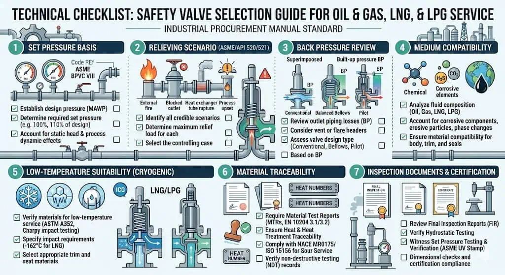
Safety valves in oil & gas, LNG/LPG, and process systems are not selected by pressure rating or connection size alone. They must be matched to the real relieving scenario, service medium, temperature range, back pressure, required relieving capacity, certified capacity basis, material compatibility, installation layout, and the code basis of the protected equipment. A valve that …
Safety valves in oil & gas, LNG/LPG, and process systems are not selected by pressure rating or connection size alone. They must be matched to the real relieving scenario, service medium, temperature range, back pressure, required relieving capacity, certified capacity basis, material compatibility, installation layout, and the code basis of the protected equipment. A valve that performs acceptably on a gas separator may fail in cryogenic LNG service or in a corrosive process system because low temperature, flashing liquids, common discharge headers, sour gas, chlorides, polymerizing media, or contaminated service can change how the valve opens, lifts, reseats, and leaks.
In practice, many failures do not start with a visibly wrong valve. They show up later as chatter, frozen moving parts, seat leakage, guide sticking, bellows failure, capacity shortfall, rejected inspection, missing documentation, or a repaired valve that cannot be returned to service under the owner’s required repair route. For users responsible for plant safety and project approval, the real task is to confirm whether the valve can protect the system during the worst credible overpressure event and whether it can be installed, maintained, tested, recertified, and documented under the applicable code.
The Williams Olefins Plant explosion and fire is a useful reminder that pressure-relief system gaps in hydrocarbon service can contribute to fire, personnel injury, asset loss, and prolonged shutdown. A relief device is often the final mechanical layer of protection when process control, alarms, and operator action are no longer sufficient.
Why Safety Valve Selection Differs Across Oil & Gas, LNG/LPG, and Process Systems
Different Industries Create Different Risk Profiles
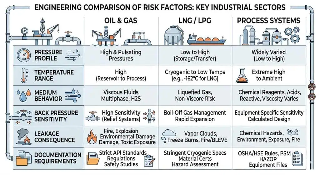
Each service creates a different combination of pressure, temperature, fluid behavior, installation limits, and consequence of release. Oil & gas systems may involve high-pressure gas, sour service, sand, scale, condensate, vibration, and flare back pressure. LNG/LPG applications add cryogenic temperature, rapid vaporization, liquid expansion, fire exposure, and discharge-location concerns. General process systems often involve corrosive chemicals, blocked outlet, thermal expansion, polymerization, fouling, tube rupture, or runaway reaction. A selection method that works for clean utility gas may not be safe for LNG boil-off, LPG storage, wet sour gas, or a reactor relief case.
The table below shows why a single selection approach does not work for every application:
Stable lift under back pressure, suitable trim and seals, adequate certified relieving capacity, NACE review where required, and reliable reseating after relief.
Material compatibility, seat integrity, resistance to fouling or plugging, and a relief basis that matches the credible upset case.
Different services create different pressure-relief risks. A valve suitable for one service may be unacceptable in another because of low temperature, back pressure, corrosive media, fouling, or release consequences.
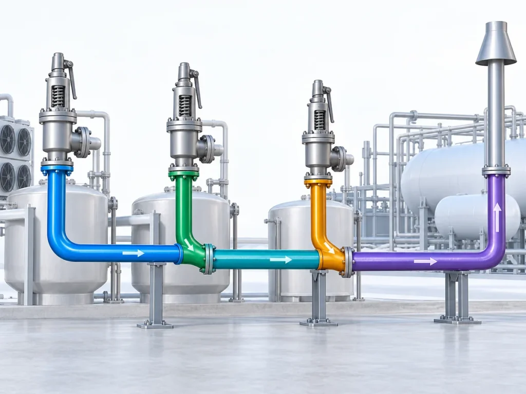
Composite field scenario for engineering training: A plant reused a conventional spring-loaded valve from a hydrocarbon service on a common flare header after a modification project. The original set pressure was unchanged, but the built-up back pressure increased because several relief devices now discharged into the same header. During an upset, the valve chattered and did not achieve stable lift. Review showed that the discharge system had changed, but the back pressure basis had not been recalculated. The corrective action was to re-evaluate the flare header, verify built-up back pressure, and replace the valve with a balanced bellows safety valve better suited to variable outlet pressure.
What Users Usually Care About Before Buying
Engineers, buyers, inspectors, and maintenance teams usually focus on practical questions before selecting a safety valve. The questions are not only commercial. They determine whether the valve can pass engineering review, inspection, commissioning, and future maintenance.
Will the valve meet the required code, certification, nameplate, and documentation route for the project?
Can it relieve the worst-case flow at the required overpressure or accumulation?
Is the material suitable for sour gas, cryogenic service, chlorides, acids, wet steam, or other aggressive media?
How sensitive is the design to superimposed or built-up back pressure?
Will it leak in normal operation, after repeated thermal cycles, or after long service close to set pressure?
Can it be tested, maintained, repaired, recertified, resealed, and documented properly during the plant life cycle?
Does the supplier provide the required test records, certified capacity basis, material traceability, and repair support?
Users also care about spare parts availability, lead time, maintenance intervals, traceability, and whether the supplier can provide the certificates and nameplate information required by the owner, EPC, or inspection authority. A lower purchase price becomes irrelevant if the valve cannot pass project approval or cannot be repaired under the required route.
Safety Valve Basics and Functions in Industrial Service
What Is a Safety Valve?
A safety valve is an automatic pressure-relieving device designed to open at a predetermined set pressure and discharge enough fluid to prevent the protected equipment from exceeding its allowable pressure limit. In gas, vapor, and steam service, “safety valve” is usually associated with rapid opening behavior. In liquid service, “relief valve” is commonly associated with more proportional opening. “Safety relief valve” can serve compressible or incompressible fluids depending on design, certification, and service conditions. In oil & gas and petrochemical plants, PSV is often used as a broad plant term, but the datasheet still needs to define the actual device type, medium, capacity basis, and code route.
In oil & gas, LNG/LPG, and process systems, safety valves protect separators, pipelines, reactors, pressure vessels, heat exchangers, fired equipment, LNG transfer systems, LPG bullets, and storage systems. They act without external power and are intended to prevent vessel rupture, piping failure, product release, fire escalation, toxic exposure, and explosion risk. For a broader terminology review, see PRV vs PSV vs safety valve vs relief valve.
Essential Functions in Process Systems
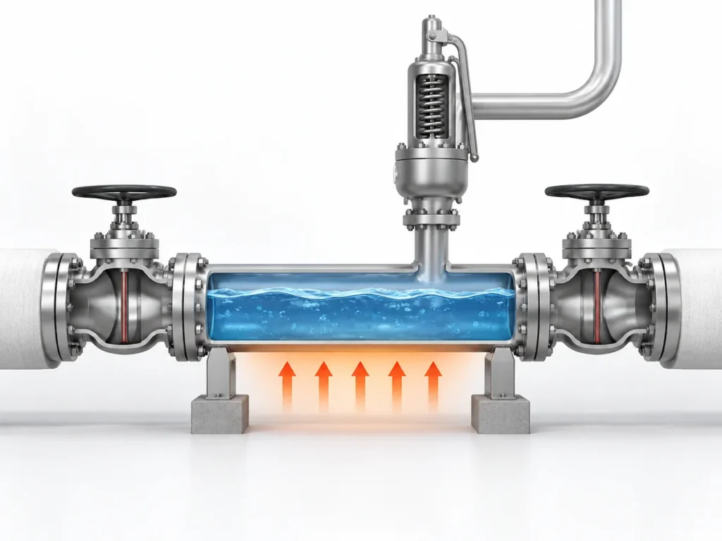
Although all safety valves serve the same basic purpose, the relieving cases differ by process. Examples include blocked outlet, thermal expansion of trapped liquid, external fire, tube rupture, control valve failure, gas blowby, runaway reaction, vapor expansion, loss of cooling, or cryogenic liquid vaporization. Each case affects required relieving capacity, relieving temperature, fluid phase, discharge routing, and back pressure.
Key functions include:
Protecting pressure vessels and pipelines: Prevents rupture of equipment such as gas separators, LNG storage tanks, LPG bullets, hydrocarbon receivers, and process vessels.
Limiting consequences of abnormal events: Reduces the chance of hydrocarbon release, fire, toxic exposure, environmental damage, or escalation to nearby equipment.
Supporting code compliance: ASME, API, ISO, National Board / NBIC, NACE, and local rules may apply depending on the equipment, location, medium, and project basis.
Maintaining plant continuity: Reliable safety valves reduce unplanned shutdowns and help operators recover safely after an upset.
Providing a documented safety layer: Correct sizing, testing, traceability, and repair records help prove that the relief system remains fit for service.
Note: A valve that meets the pressure class of the piping is not automatically suitable as a pressure-relief device. The decisive check is whether it has sufficient certified relieving capacity at the required relieving conditions and whether its materials, seat design, valve type, and back pressure limits fit the service.
Application Area
Example System
Typical Relieving Concern
Pressure Vessels
Gas separators, surge drums, LNG tanks, LPG storage vessels.
Fire case, blocked outlet, gas blowby, control valve failure.
Piping Systems
LNG transfer lines, LPG loading lines, hydrocarbon pipelines.
Thermal expansion of trapped liquid, blocked line, vaporization after heat input.
Chemical Processing
Reactors, columns, exchangers, polymer units.
Runaway reaction, tube rupture, vapor expansion, polymerization or plugging.
LPG Storage
Bullets, spheres, transfer systems.
Fire case, liquid expansion, vapor pressure rise, safe discharge location.
Safety Valve Types for Oil & Gas, LNG/LPG, and Process Systems
Spring-Loaded Safety Valves
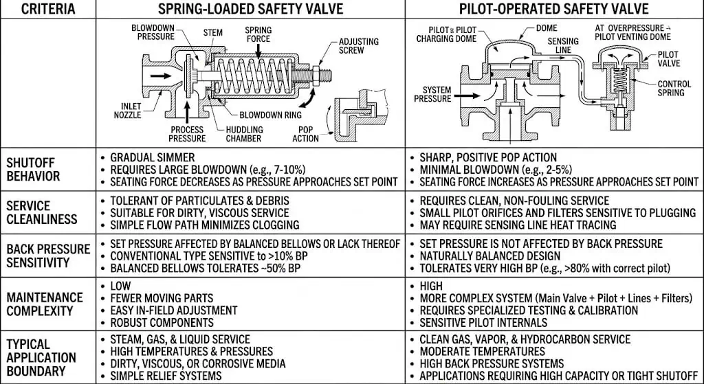
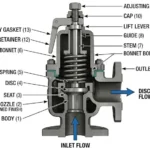
Spring-loaded safety valves remain common in oil & gas and process systems because they are simple, widely available, and well understood. A calibrated spring holds the disc closed until the set pressure is reached. These valves work well for many gas, vapor, steam, and utility services, but conventional designs can be sensitive to back pressure and may leak, flutter, or chatter if the inlet or discharge piping is poorly designed.
Suitable for many gas, vapor, steam, and general process applications.
Simple mechanical design and straightforward maintenance.
Conventional designs may be affected by superimposed or built-up back pressure.
Seat tightness and stability depend on service cleanliness, inlet piping, outlet piping, blowdown, and operating margin.
Balanced bellows versions may be considered where variable outlet pressure must be managed within design limits.
A common field problem occurs when a spring-loaded valve is installed on a long inlet branch with several fittings and a shared discharge header. The valve opens at the correct set pressure on the bench, but in service the inlet pressure drops rapidly after lift while outlet pressure rises. The result is chatter and seat damage. The prevention is to review inlet pressure loss, outlet resistance, and valve type before the valve is released for purchase.
Pilot-Operated Safety Valves
Pilot-operated safety valves use a smaller pilot valve to control the main valve. They are often selected where tight shutoff is important, where operating pressure is close to set pressure, where large capacity is needed in a compact arrangement, or where certain back pressure conditions make a conventional design less suitable. In clean gas service, they can be very effective. In dirty, freezing, waxy, polymerizing, or hydrate-prone service, the pilot circuit becomes part of the reliability risk.
Pilot-operated valves are not a universal upgrade. Their pilot lines, filters, sensing passages, and small clearances can be affected by solids, condensate, wax, freezing, corrosion products, or polymerizing media. Before selection, engineers should review service cleanliness, winterization, pilot line routing, maintenance access, and whether the owner accepts the pilot-operated design under the applicable code and inspection route.
Feature
Pilot-Operated Safety Valves
Spring-Loaded Safety Valves
Operation
Uses a pilot valve to control the main valve.
Relies on spring force to keep the disc closed.
Shutoff Performance
Often tighter near operating pressure when service is clean and suitable.
Acceptable in many services but may leak if operating too close to set pressure.
Back Pressure Tolerance
Often better in variable back pressure service, depending on design.
Conventional type may be sensitive; balanced bellows improves performance within limits.
Service Cleanliness
Pilot passages can plug, freeze, or foul in dirty service.
Generally more tolerant of contaminated service, depending on trim and seat design.
Typical Use
High-pressure gas systems, minimal leakage requirement, large capacity, high operating pressure ratio.
General process service, steam, air, many gas and vapor applications.
Spring-loaded valves are common and simple, while pilot-operated valves may offer tighter shutoff and higher capacity at high operating pressure ratios. Dirty, freezing, or fouling service must be evaluated carefully before selecting a pilot design.
Composite field scenario for engineering training: A pilot-operated valve was selected on a gas system to reduce leakage because normal operating pressure was close to set pressure. The service later contained fine solids and condensate. After a cold spell, the pilot tubing became unstable and the valve failed to reseat cleanly. The root cause was not the set pressure but the unsuitability of the pilot circuit for dirty and cold service. The corrective action was to review service cleanliness, provide heat tracing or protection where required, and consider a spring-loaded or balanced bellows design if fouling could not be controlled.
Safety Relief Valves for LPG
LPG systems require careful attention to both vapor and liquid behavior. Fire exposure, liquid expansion in blocked-in sections, and rapid vapor generation must all be considered. Relief devices must be positioned and vented to reduce the risk of flammable cloud formation near operators, traffic areas, building openings, or ignition sources. LPG valves also need reliable seat tightness because small leakage can create odor complaints, flammable vapor accumulation, and operating losses.
For LPG storage containers, operators typically review:
Whether the valve is sized for the governing fire case, thermal expansion case, or other relieving scenario.
Whether materials and seals are compatible with propane, butane, mixed LPG, low ambient temperatures, and cleaning fluids.
Whether the valve has been inspected, tested, and replaced at intervals required by local regulations, owner procedures, or service history.
Whether the discharge point is safe and does not create unacceptable fire, asphyxiation, or ignition risk.
Whether discharge piping creates excessive back pressure or liquid pockets.
Safety relief valves for LPG storage and transport must be maintained and inspected under the relevant codes, owner requirements, or national regulations. After fire exposure, overpressure event, mechanical damage, or abnormal leakage, the valve should be removed from service, inspected, and requalified or replaced as required.
Specialty Valves for LNG Facility
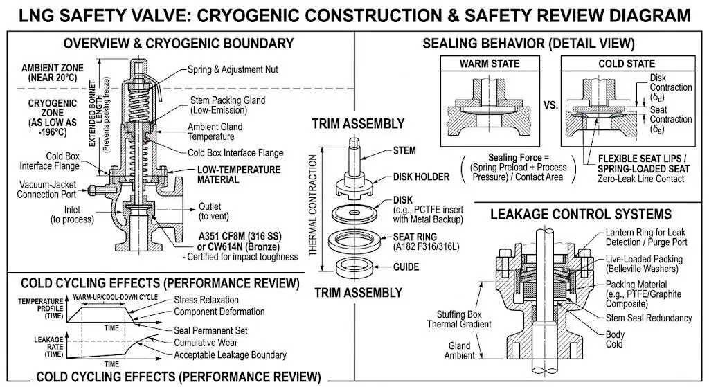
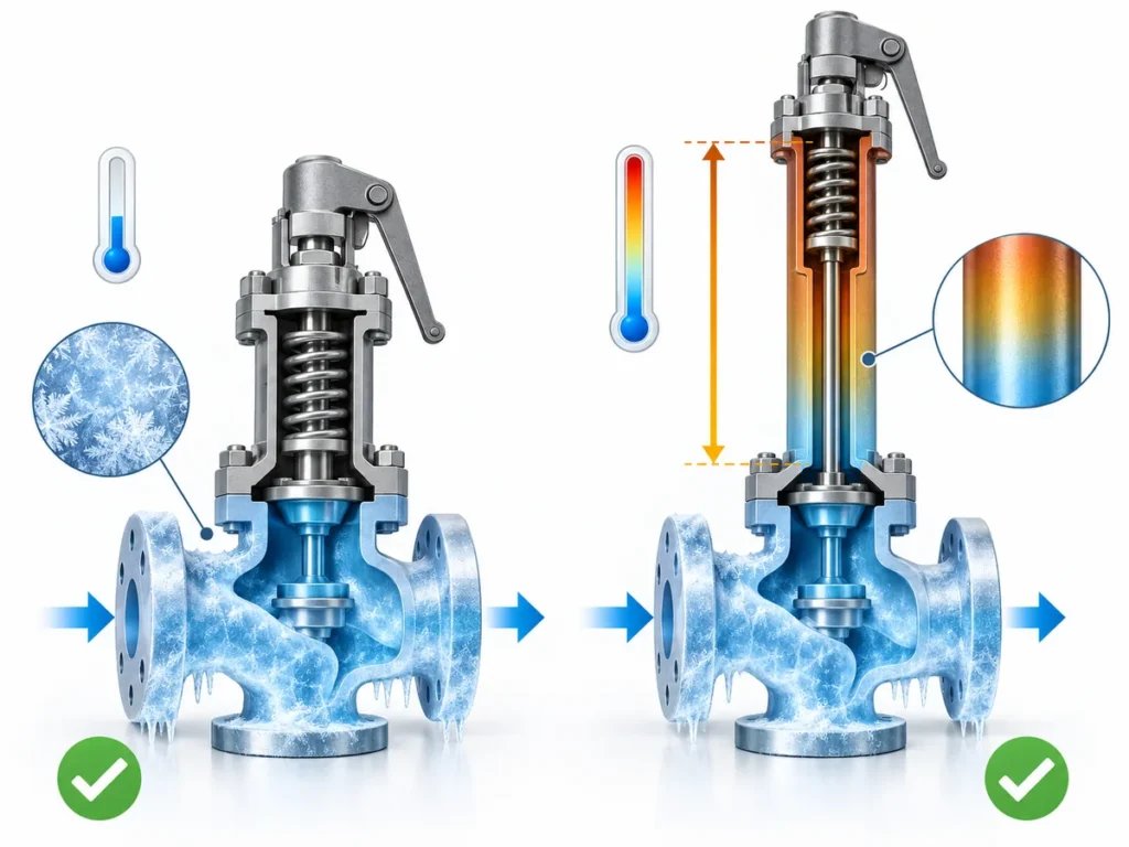
LNG service introduces extreme low temperature and rapid phase change. Cryogenic valves must retain toughness, dimensional stability, and sealing performance at temperatures far below ambient. Materials commonly used in LNG service include austenitic stainless steels and suitable nickel-based alloys. Carbon steels that perform adequately at ambient temperature may become brittle in cryogenic conditions unless they are specifically qualified for the low-temperature duty.
In LNG service, material toughness at cryogenic temperature, thermal contraction, seat sealing, and vent arrangement must be checked carefully.
Design considerations for LNG include:
Materials that maintain impact toughness at cryogenic temperature.
Sealing performance after repeated cooldown and warm-up cycles.
Protection of moving parts against freezing, icing, or water ingress.
Vent routing to avoid cold vapor accumulation or unsafe discharge near personnel.
Compatibility of test methods, cleaning, documentation, and degreasing with low-temperature service.
Consideration of oxygen-deficiency hazard and cold-burn risk where discharge can accumulate.
Composite field scenario for engineering training: An LNG transfer line was fitted with a valve using materials suitable for ambient service but not verified for cryogenic duty. After repeated cooldown cycles, leakage developed because thermal contraction affected the seating surfaces and a non-cryogenic gasket lost integrity. The corrective action was to select cryogenic-grade materials and seals, verify low-temperature testing, and review installation details that could impose thermal stress.
Technical Specifications of Safety Protection Valves
Pressure Ratings and Set Points
Set pressure is the pressure at which the safety valve is adjusted to open under defined test conditions. It affects when the valve begins to relieve. Overpressure is the pressure increase above set pressure during a relieving event. Accumulation is the pressure increase above the protected equipment’s allowable pressure boundary. Blowdown is the difference between opening pressure and reseating pressure. These terms must be reviewed together because they define when the valve opens, how much pressure rise is accepted, and where the valve closes after discharge.
For pressure vessels, set pressure must be tied to the protected equipment limit and the governing code basis. Users should not set a valve above the protected equipment’s allowable limit unless the applicable code and project basis explicitly allow the arrangement. The operating pressure should also remain far enough below set pressure to avoid simmer, leakage, or nuisance lifting. For a deeper explanation, see set pressure, overpressure, accumulation, and blowdown in safety valves.
Set pressure must align with the MAWP or protected equipment limit required by the governing code basis.
Operating pressure should be below set pressure enough to avoid nuisance leakage, simmer, or chatter.
Overpressure and accumulation limits depend on the equipment, code route, number of devices, and relieving case.
For backup relief devices, multiple valves, or special systems, project specifications may define different settings.
After maintenance, set pressure should be verified, documented, and resealed according to the required repair route.
Set pressure alone does not guarantee protection. The valve must also relieve the required mass or volumetric flow at the appropriate overpressure or accumulation and remain stable under the expected inlet and outlet conditions.
Temperature Limits and Thermal Stability
Temperature affects materials, spring characteristics, seat tightness, gasket behavior, bellows fatigue, and the mechanical integrity of the body, nozzle, disc, guide, spindle, bellows, and seals. In cryogenic service, low temperature can embrittle unsuitable materials and change clearances due to thermal contraction. In hot hydrocarbon or steam service, spring relaxation, gasket degradation, oxidation, and thermal distortion may affect performance.
Cryogenic valves require materials and seals verified for the actual low-temperature duty.
High-temperature hydrocarbon or steam service may require alloy steels, high-temperature trim, or metal seats.
Thermal cycling can increase seat leakage over time, especially when the valve operates close to set pressure.
Elastomeric seals require careful compatibility review for both temperature and media.
Cold service may require drainage, protection against water ingress, and review of icing or freezing risk.
This is a typical engineering experience range; the final material and seal choice depends on medium, pressure, temperature, back pressure, valve type, installation, manufacturer data, and project certification requirements.
Flow Capacity and Sizing
Relieving capacity is one of the most important selection criteria. Engineers calculate the required orifice area based on the governing relief scenario and fluid properties. Connection size alone does not indicate capacity; two valves with the same inlet and outlet size may have different certified orifice letters, flow coefficients, and rated capacity. For process-industry work, API 520 safety valve sizing is often used to support sizing and selection, while API 521 is used to review pressure-relieving and depressuring systems.
Sizing Factor
Why It Matters
Relieving Scenario
Blocked outlet, fire case, tube rupture, thermal expansion, gas blowby, or reaction upset determine the required flow.
Fluid State
Gas, vapor, liquid, flashing liquid, or two-phase flow influence equations and discharge behavior.
Set Pressure and Accumulation
Determine the relieving pressure available to drive flow.
Back Pressure
Can reduce effective relieving capacity and change lift stability.
Certified Orifice Area
Determines the rated discharge capacity of the valve.
Inlet Pressure Loss
Can cause unstable lift or chatter if excessive during relieving flow.
Common references include API 520 Part I for sizing and selection, API 520 Part II for installation, API 521 for pressure-relieving and depressuring systems, API 526 for flanged steel pressure relief valves, and ISO 4126 for international safety valve product requirements. The buyer should always confirm which standard the owner or inspection body requires before accepting the sizing basis.
Material Selection and Compatibility
Material selection affects corrosion resistance, seat leakage, service life, repairability, and compliance with sour service or low-temperature requirements. Users should not evaluate body material alone. They should confirm materials for nozzle, disc, guide, spindle, spring, bellows, gaskets, and soft seals where applicable. For severe service, the wetted trim often fails before the body shows visible damage.
Service Condition
Material / Design Concern
Typical Approach
Sour Gas / H2S
Sulfide stress cracking and hydrogen-related damage.
Review NACE MR0175 / ISO 15156 material limits where required by the project.
Use cryogenic-grade stainless or nickel alloys; confirm low-temperature testing and documentation.
Chlorides / Seawater
Pitting and stress corrosion cracking.
Select suitable stainless, duplex, super duplex, or corrosion-resistant alloys according to temperature and chloride level.
Acidic / Corrosive Process
Nozzle, disc, guide, spring, and bellows corrosion.
Choose corrosion-resistant trim, bellows material, or lined solutions where appropriate.
Dirty or Polymerizing Media
Plugging, sticking, seat fouling, pilot circuit instability.
Review trim design, pilot suitability, drain provisions, cleaning access, and maintenance interval.
Composite field scenario for engineering training: A process valve was selected with a stainless body, but the nozzle and guide material were not compatible with chloride-bearing condensate. The body looked acceptable during external inspection, yet seat leakage increased and the disc showed corrosion marks after removal. The cause was trim-level corrosion, not body failure. The corrective action was to specify wetted trim materials explicitly and review chloride, temperature, and condensate chemistry before ordering.
Industry Standards and Compliance
API and ASME Codes
Relief device selection in oil & gas, LNG/LPG, and process systems usually involves more than one code. These standards do not all answer the same question. ASME BPVC Section VIII defines pressure vessel rules and certification framework. API 520 Part I supports sizing and selection. API 520 Part II supports installation review. API 521 supports pressure-relieving and depressuring system analysis. API 527 supports seat tightness testing. API RP 576 supports inspection of pressure-relieving devices.
Seat tightness test methods and acceptance basis for pressure relief valves.
API RP 576
Inspection of pressure-relieving devices.
ASME B31.3 / B31.4 / B31.8
Process piping, liquid pipeline, and gas pipeline requirements where applicable.
These documents affect how engineers size, install, test, and document safety valves. For example, installation review must consider inlet pressure loss, outlet loads, discharge routing, and piping support; seat tightness should be tested under the applicable project-accepted method; and repair records must show that the valve was recalibrated and sealed correctly after maintenance.
ISO and International Certifications
Global projects may require compliance with ISO 4126, PED/CE, National Board requirements, or local regulations in addition to API or ASME. These certifications help confirm that the valve has been designed, tested, marked, and documented according to recognized procedures. End users should verify what the owner, EPC, inspection body, insurer, or local authority requires before issuing the purchase order.
Repair of pressure relief valves by authorized organizations.
Important where the project, owner, or jurisdiction requires a recognized repair route.
NACE MR0175 / ISO 15156
Sour service.
Helps avoid sulfide stress cracking and material failure in H2S-containing service.
Documentation and Traceability
Safety valves should be fully traceable from manufacture to service and repair. Traceability is especially important in hydrocarbon, toxic, cryogenic, sour, and regulated service. A valve without correct documents may be mechanically usable but still unacceptable to the owner or inspector.
Typical documentation includes:
Approved datasheets and sizing calculations.
Material test certificates and heat numbers where required.
Certified capacity or type test reports where required.
Set pressure test records and seat tightness test results.
Calibration certificates for test equipment.
Third-party inspection or witness records if required.
Maintenance, repair, recalibration, and recertification history linked to valve serial numbers.
Lead seal or tamper-evident sealing records after adjustment.
Composite field scenario for engineering training: A replacement valve passed a bench test but was later rejected by the owner because the supplier could not provide certified capacity documentation and traceable material certificates for sour-service trim. The problem was not the external appearance of the valve but the lack of documentation required for approval and long-term traceability. The corrective action was to obtain properly certified equipment with complete records and align procurement with the project datasheet and code basis. A controlled safety valve RFQ datasheet helps prevent this problem before ordering.
Selecting Safety Valve Solutions
Assessing System Pressure and Temperature
Selection starts with the relieving case and the protected equipment. Engineers need to know the MAWP, normal operating pressure, set pressure, allowable overpressure or accumulation, blowdown expectation, relieving temperature, fluid state, and whether the relief case is gas, vapor, liquid, flashing liquid, or two-phase flow.
Set pressure must align with the code basis of the protected equipment.
Normal operating pressure should stay low enough below set pressure to minimize simmer or leakage.
Relieving temperature affects density, viscosity, material strength, seat behavior, and required orifice area.
For LNG, low-temperature contraction, icing, water ingress, and cryogenic material toughness may influence design and maintenance requirements.
For hot hydrocarbon or steam service, spring relaxation, gasket degradation, and thermal distortion may affect long-term tightness.
Identifying Process Medium
The process medium affects valve type, material selection, seat design, discharge routing, and maintenance strategy. Users should ask not only “What is the fluid?” but also “Can it corrode, polymerize, freeze, flash, foul the trim, block a pilot passage, or attack a soft seat?”
Media Type
Selection Concern
Typical Choice / Action
Clean Gas / Vapor
Back pressure, seat tightness, certified capacity.
Conventional, balanced bellows, or pilot-operated depending on back pressure and leakage requirements.
Corrosive Media
Body, trim, bellows, and spring corrosion.
Select corrosion-resistant materials and confirm compatibility for all wetted parts.
Dirty / Solid-Laden Service
Plugging, disc sticking, pilot fouling, seat damage.
Prefer designs tolerant of contamination and review maintenance frequency.
Review relief scenario, cleaning access, material compatibility, and valve type carefully.
Environmental and Site Conditions
Outdoor installation, marine atmosphere, corrosive vapors, ambient temperature swings, vibration, fire exposure, and discharge location all affect safety valve performance. In cold climates, pilot lines or discharge piping may require tracing or weather protection. In marine or offshore service, external corrosion, vibration resistance, nameplate durability, and access for inspection become more important.
Condition
Impact on Safety Valve Performance
Variable Back Pressure from Flare Header
May require balanced bellows or pilot-operated design, subject to service cleanliness and manufacturer limits.
Low Ambient or Cryogenic Exposure
Can freeze pilot tubing, affect sealing, or create ice around discharge components.
Corrosive Atmosphere / Marine Service
May corrode external parts, springs, fasteners, vent screens, and nameplates.
Vibration or Pulsation
Can cause premature wear, leakage, or unstable lift.
Fire Exposure
Can define the governing relief case and require review of discharge direction and valve condition after exposure.
Installation Considerations
Improper installation is a common cause of field problems even when the valve itself is correctly selected. API 520 Part II and manufacturer instructions provide guidance on inlet piping, discharge piping, support, orientation, reaction forces, and drainage. For practical installation details, see the safety valve installation guide.
Best practices include:
Install the valve in the recommended orientation; many safety valves are intended for vertical installation.
Keep inlet piping short and sized to limit pressure loss under relieving flow.
Support heavy discharge piping to avoid excessive load on the valve body.
Provide drainage where condensate accumulation could affect operation.
Ensure discharge is routed to a safe location, vent system, or flare system.
Protect soft parts, bellows, springs, and pilot tubing from freezing, dirt, corrosion, or mechanical damage.
Review discharge reaction forces, noise, vibration, and thermal movement before commissioning.
Tip: Many chattering problems are caused not by the valve spring or set point but by excessive inlet pressure loss, poor piping support, oversized valves, or increased back pressure after system modifications.
Maintenance and Risk Mitigation for Safety Protection Valves
Routine Inspection Procedures
Routine inspection helps identify seat leakage, corrosion, stuck trim, broken springs, damaged bellows, missing seals, blocked vents, pilot line problems, or incorrect nameplate data before the valve is needed in service. Inspection interval depends on service severity, cleanliness, regulatory requirements, owner program, and historical performance. Dirty, corrosive, cryogenic, cyclic, sour, or high-consequence service typically justifies more conservative inspection planning than clean utility service.
Check for visible leakage, corrosion, icing, vibration damage, or external mechanical damage.
Verify tag, seal, nameplate, set pressure, and service information.
Review discharge piping, supports, drains, and evidence of back pressure problems.
Confirm maintenance records, set pressure test dates, and seat tightness results.
Inspect for process deposits, corrosion, erosion, or guide sticking on removed valves.
Check pilot filters, sensing lines, winterization, and drain arrangements on pilot-operated valves.
Preventive Maintenance Strategies
Preventive maintenance reduces unexpected failure and supports audit readiness. Depending on service, companies may apply scheduled removal and bench testing, on-site testing, condition-based inspection, or shorter intervals after abnormal operation. After repair, the valve should be recalibrated, seat-tested, documented, and resealed according to the applicable project, regulatory, or owner route.
Strategy
Description
Scheduled Inspection
Remove and inspect valves at planned intervals based on service severity and regulations.
Set Pressure Verification
Confirm opening pressure remains within the project-accepted tolerance.
Seat Tightness Testing
Check leakage using API 527 or other applicable procedures where required.
Cleaning / Refurbishment
Remove deposits, repair seats, replace damaged springs, seals, bellows, gaskets, or pilot parts.
Condition Review After Upset
Inspect valve after overpressure event, fire exposure, severe vibration, or abnormal process condition.
Repair Route Verification
Confirm whether National Board / VR, local inspection, or owner-approved repair procedure is required.
Common Failure Modes
Failure modes vary with service and valve type, but several patterns occur repeatedly in oil & gas, LNG/LPG, and process plants.
Seat leakage: Can be caused by dirt, corrosion, worn seats, operating too close to set pressure, thermal cycling, or improper handling.
Chatter / flutter: Often related to excessive inlet pressure loss, built-up back pressure, oversized valves, unstable process pressure, or poor discharge piping.
Bellows failure: May expose the spring housing to corrosive discharge and change valve behavior.
Frozen or sticking parts: Common in cryogenic, wet gas, or contaminated service when drainage and winterization are poor.
Corrosion or erosion: Can damage nozzle, disc, guide, spring, bellows, or soft seats.
Set pressure drift after repair: Can be caused by incorrect adjustment, damaged spring, wrong parts, or inadequate testing.
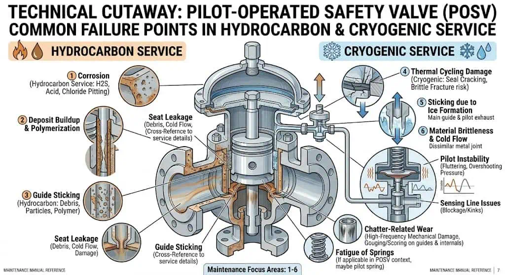
Pilot circuit instability: Can occur when sensing lines, filters, or pilot passages are exposed to dirt, wax, hydrates, condensate, or freezing.
Common failure points include seat damage, corrosion, bellows failure, sticking due to deposits or freezing, and chatter caused by poor inlet or outlet conditions.
Composite field scenario for engineering training: A process unit reported repeated seat leakage after turnaround. Review found that the valve had been reinstalled with poor inlet piping support and the system was operating close to set pressure. Minor vibration and frequent simmer damaged the seating surfaces. The corrective action was to review operating margin, improve inlet piping support, confirm set pressure and bench test results, and inspect seat condition using the applicable leakage test.
Risk Assessment Techniques
Pressure-relief devices are usually reviewed as part of broader process safety analysis such as HAZOP, LOPA, FMEA, fire case assessment, management of change, and periodic relief-system revalidation. Relief scenarios are not chosen arbitrarily; they are linked to credible process upsets, external fire exposure, blocked lines, tube rupture, gas blowby, control failure, loss of cooling, and other events identified in the risk review.
Technique
Why It Helps
HAZOP / LOPA
Identifies credible overpressure causes, safeguards, and consequence severity.
FMEA
Reviews component failure modes such as spring breakage, bellows failure, pilot plugging, or seat damage.
Fire Case Review
Assesses relief demand during external fire exposure, especially for LPG and hydrocarbon equipment.
Periodic Revalidation
Confirms that old valves still fit modified process conditions, flare headers, and operating envelopes.
Management of Change
Captures changes in piping, capacity, control philosophy, relief headers, or process chemistry before they affect PSV performance.
Best Practices for Safety Valve Management
Training and Competency
Personnel involved in selection, installation, and maintenance of safety valves need practical training, not just awareness of terminology. Teams should understand how set pressure, overpressure, accumulation, blowdown, required relieving capacity, certified capacity, back pressure, service medium, material compatibility, and code requirements affect performance. They should also recognize signs of leakage, chatter, corrosion, icing, blocked pilot lines, and missing documentation.
Train engineers and technicians on selection, sizing, installation, inspection, and testing requirements.
Ensure maintenance teams understand seal wire, nameplate, recalibration, and recertification requirements.
Review incident history and failure patterns during training.
Include cold-service, sour-service, LPG fire exposure, and flare-header back pressure precautions where applicable.
Train procurement teams to request capacity basis, test records, material certificates, and repair route information before purchase.
Recordkeeping and Traceability
Good recordkeeping supports compliance, troubleshooting, and lifecycle cost control. Each valve should have traceable records of set pressure, service location, test results, repair history, material certificates where required, and current seal status. Records are especially important when valves are moved between services, repaired after leakage, or replaced during turnaround.
Practice
Benefit
Accurate Maintenance Records
Supports audit readiness, trend review, and inspection planning.
Traceable Serial Numbers and Tags
Links each valve to approved datasheets, certificates, and service location.
Heat Number and Material Records
Confirms compliance for sour service, cryogenic service, or special alloy valves.
Documented Repair and Recertification
Improves confidence in field performance after maintenance.
Failure History Tracking
Helps identify repeated leakage, chatter, corrosion, or pilot circuit problems.
Emergency Response Planning
Facilities should plan for cases where a relief device opens, leaks, or fails. Emergency response plans typically include safe isolation, evacuation, flare handling, communication protocols, and coordination with external responders when necessary. Discharge to atmosphere in LPG, sour gas, toxic, or flammable hydrocarbon service requires especially careful review of ignition sources, wind direction, occupied areas, low points, and ventilation.
Identify likely emergency release scenarios.
Provide clear contact lists and communication procedures.
Train operators on abnormal indications such as sustained venting, icing, vibration, or unexpected odor.
Conduct drills and update the plan when systems, relief headers, operating envelopes, or storage arrangements change.
Define when a valve must be removed, inspected, repaired, recertified, or replaced after a relief event.
What buyers and engineers should verify before ordering or replacement:
Before ordering, confirm set pressure, certified capacity, service medium, material compatibility, back pressure, low-temperature or sour-service requirements, certifications, and documentation.
Pre-Order Check
Why It Matters
Set Pressure / MAWP
Ensures code compliance and safe opening point.
Required Relieving Capacity
Confirms the valve can protect the worst-case scenario.
Certified Capacity / Orifice Area
Prevents the common mistake of selecting by connection size alone.
Back Pressure
Affects lift stability, effective capacity, blowdown, and valve type selection.
Service Medium
Determines valve type, materials, soft seat suitability, and maintenance interval.
Temperature Range
Critical for LNG, LPG, hot hydrocarbon, steam, and thermal cycling service.
Material Compatibility
Prevents corrosion, embrittlement, stress cracking, guide sticking, or seat leakage.
Certification / Code Basis
Supports project approval and audit readiness.
Documentation and Traceability
Required for inspection, repair, recertification, and lifecycle management.
Safety valve selection in oil & gas, LNG/LPG, and process systems depends on the real relieving scenario, service medium, temperature range, back pressure behavior, material compatibility, discharge routing, installation layout, inspection route, and project compliance basis. Users should not reduce selection to pressure class or connection size. Many field failures result from capacity shortfall, underestimated back pressure, unsuitable materials, dirty service, frozen pilot circuits, or incomplete documentation rather than from the valve body itself.
Review selection, installation, inspection, repair, and recertification as one continuous lifecycle process.
Reassess valves after process modifications, flare header changes, corrosion findings, fire exposure, or repeated leakage.
Use certified capacity and code-based calculations rather than nominal size alone.
Apply practical field experience when selecting designs for cryogenic, dirty, corrosive, sour, high-pressure, or LPG fire-case service.
Proactive management of safety valves helps reduce unexpected shutdowns, improve audit readiness, and protect people and assets when abnormal pressure occurs.
FAQ
What is the main function of a safety valve in process systems?
The main function is to protect equipment and personnel by automatically relieving excess pressure before the protected system exceeds its allowable limit.
Prevents vessel or piping rupture.
Reduces risk of fire, explosion, toxic release, or environmental damage.
Supports code compliance, inspection acceptance, and plant continuity.
How often should safety valves undergo inspection and maintenance?
Inspection interval depends on service severity, regulatory requirements, owner procedures, and operating history. There is no single interval that fits every oil & gas, LNG/LPG, or process service. Dirty, corrosive, cryogenic, sour, cyclic, or high-consequence service usually needs more conservative inspection planning than clean utility service.
Inspect sooner after any overpressure event, fire exposure, abnormal leakage, or evidence of chatter.
Follow local code, company procedures, owner specifications, and manufacturer recommendations.
Use shorter intervals for dirty, corrosive, cryogenic, sour, or cycling service.
Which factors determine the correct safety valve selection?
Factor
Why It Matters
Set Pressure
Determines when the valve opens relative to MAWP or the protected equipment limit.
Required Relieving Capacity
Ensures the valve can handle the worst credible overpressure scenario.
Back Pressure
Influences stable lift, effective capacity, blowdown, and reseating.
Material Compatibility
Prevents corrosion, stress cracking, freezing, brittle failure, or seat damage.
Service Medium and Temperature
Determine valve type, trim, spring, bellows, and seal suitability.
Certification / Documentation
Required for project approval, inspection, repair, and traceability.
Engineers should review all of these factors together instead of selecting by size or pressure class alone.
Can one safety valve type serve all applications?
No. Different applications require different valve types, materials, certification routes, and installation details.
Spring-loaded valves suit many general gas, vapor, and steam services.
Pilot-operated valves may be better when tight shutoff or higher capacity is required, but dirty or freezing service can be a limitation.
Balanced bellows valves may be reviewed where variable back pressure affects conventional valves.
Cryogenic or sour service requires specialized material review and testing.
Why is documentation important for safety valve management?
Documentation provides traceability, supports audits, and verifies that the valve meets the required code, material, capacity, and performance criteria.
Links certificates and repair history to valve serial numbers.
Confirms certified capacity, set pressure, material route, and test results.
Simplifies regulatory inspections and future troubleshooting.
Supports repair, recalibration, resealing, and recertification decisions.
How does back pressure affect safety valve performance?
Back pressure can change how the valve opens, how much it relieves, and how it reseats.
Superimposed back pressure exists before the valve opens and may alter force balance.
Built-up back pressure develops after opening because of discharge piping resistance.
Excessive back pressure can cause chatter, reduce effective capacity, or prevent stable lift.
Conventional, balanced bellows, and pilot-operated valves respond differently, so valve type must match outlet conditions.
What materials are commonly used for LNG safety valves?
Cryogenic LNG service typically uses materials that retain toughness at very low temperatures, such as suitable austenitic stainless steels and nickel-based alloys.
Material must resist brittle fracture and thermal contraction.
Seals and gaskets must remain functional at low temperature.
Cryogenic testing and documentation should be verified before use.
Carbon steel should not be assumed suitable unless the specific grade and temperature rating are verified.
Why is certified relieving capacity more important than connection size?
Connection size only shows whether the valve can be installed. Certified relieving capacity shows whether it can actually pass the required flow during the governing overpressure case. A valve can match the nozzle and still be undersized if the orifice area or certified capacity is inadequate.
Why does a safety valve leak after installation?
Leakage after installation can come from seat damage, dirt, improper handling, operating too close to set pressure, thermal distortion, corrosion, vibration, back pressure, or incorrect recalibration after repair. Troubleshooting should compare shop test records with installed conditions and then review operating pressure, inlet cleanliness, outlet loads, seat material, and service history.
To provide the best experiences, we use technologies like cookies to store and/or access device information. Consenting to these technologies will allow us to process data such as browsing behavior or unique IDs on this site. Not consenting or withdrawing consent, may adversely affect certain features and functions.
Functional
Always active
The technical storage or access is strictly necessary for the legitimate purpose of enabling the use of a specific service explicitly requested by the subscriber or user, or for the sole purpose of carrying out the transmission of a communication over an electronic communications network.
Preferences
The technical storage or access is necessary for the legitimate purpose of storing preferences that are not requested by the subscriber or user.
Statistics
The technical storage or access that is used exclusively for statistical purposes.The technical storage or access that is used exclusively for anonymous statistical purposes. Without a subpoena, voluntary compliance on the part of your Internet Service Provider, or additional records from a third party, information stored or retrieved for this purpose alone cannot usually be used to identify you.
Marketing
The technical storage or access is required to create user profiles to send advertising, or to track the user on a website or across several websites for similar marketing purposes.