Compressor safety valve selection should start with the relief duty, not with a valve size or architecture. Define what needs protection, the governing overpressure case, required relieving capacity, and actual service conditions first. Then determine how compressor pressure pulsation, relieving temperature, and back pressure change the suitability of the exact valve candidate. Those three conditions …

Compressor safety valve selection should start with the relief duty, not with a valve size or architecture. Define what needs protection, the governing overpressure case, required relieving capacity, and actual service conditions first. Then determine how compressor pressure pulsation, relieving temperature, and back pressure change the suitability of the exact valve candidate.
Those three conditions do not form a universal formula for choosing a spring-loaded, balanced, or pilot-operated valve. They affect different parts of the same decision: actuation, dynamic stability, capacity, component limits, and installed-system behavior.
This guide uses compressor safety valve for the application context and pressure-relief valve (PRV) when discussing the engineering behavior of the protective device. For broader compressor application context, see ZOBAI’s compressor safety valve applications guide.
What Must Be Defined Before Selecting a Compressor Safety Valve?
Before comparing compressor safety valve candidates, define the protected pressure boundary, pressure basis, governing relief scenario, required relieving load, fluid condition, relieving temperature, dynamic inlet condition, and downstream pressure condition.
If one of those inputs can materially change sizing or suitability, leaving it undefined means the valve selection is not yet ready to close.
| Input to define | Decision it enables | What remains unresolved if missing |
|---|---|---|
| Protected pressure boundary | What actually requires overpressure protection | Protection basis |
| Applicable pressure basis | Set-pressure review | Whether the proposed setting is appropriate |
| Governing overpressure scenario | Why relief is required | Basis for the required load |
| Required relieving capacity | Capacity screening | Whether the candidate can pass the required load |
| Fluid and relevant state | Sizing and compatibility basis | Applicable fluid assumptions |
| Relieving conditions | Capacity and service review | Candidate performance at the governing condition |
| Relevant pressure dynamics | Dynamic review where pulsation matters | Valve/system behavior |
| Back pressure / discharge condition | Outlet-system and architecture screening | Opening or capacity effects |
| Material / compatibility requirements | Component configuration | Service compatibility |
| Project basis | Required code and documentation review | Project acceptance requirements |
Set pressure is not relieving capacity. The pressure basis determines when overpressure protection should act; relieving capacity determines whether the selected valve can discharge the required load under the applicable conditions. A candidate can satisfy one requirement without satisfying the other.
Connection size is not required capacity. An existing nozzle or flange is an installation constraint. It does not establish the relieving load. Likewise, an old valve nameplate is useful replacement evidence, but it should not silently replace confirmation of the current relief duty.
The same duty-first logic applies to service conditions. Gas service may not sufficiently describe the fluid properties or state needed for sizing. Normal compressor temperature may differ from the temperature during the governing relief case. Downstream pressure may affect both valve behavior and available capacity.
For detailed capacity calculations and orifice-selection considerations, see ZOBAI’s safety valve sizing and certified relieving capacity guide.
A practical order is: define the protected duty → establish required relief performance → define actual service conditions → screen the valve candidate.
How Does Compressor Pulsation Change Safety Valve Selection?
Pressure pulsation is a dynamic system condition; chatter is a valve-behavior phenomenon. They are not interchangeable terms.
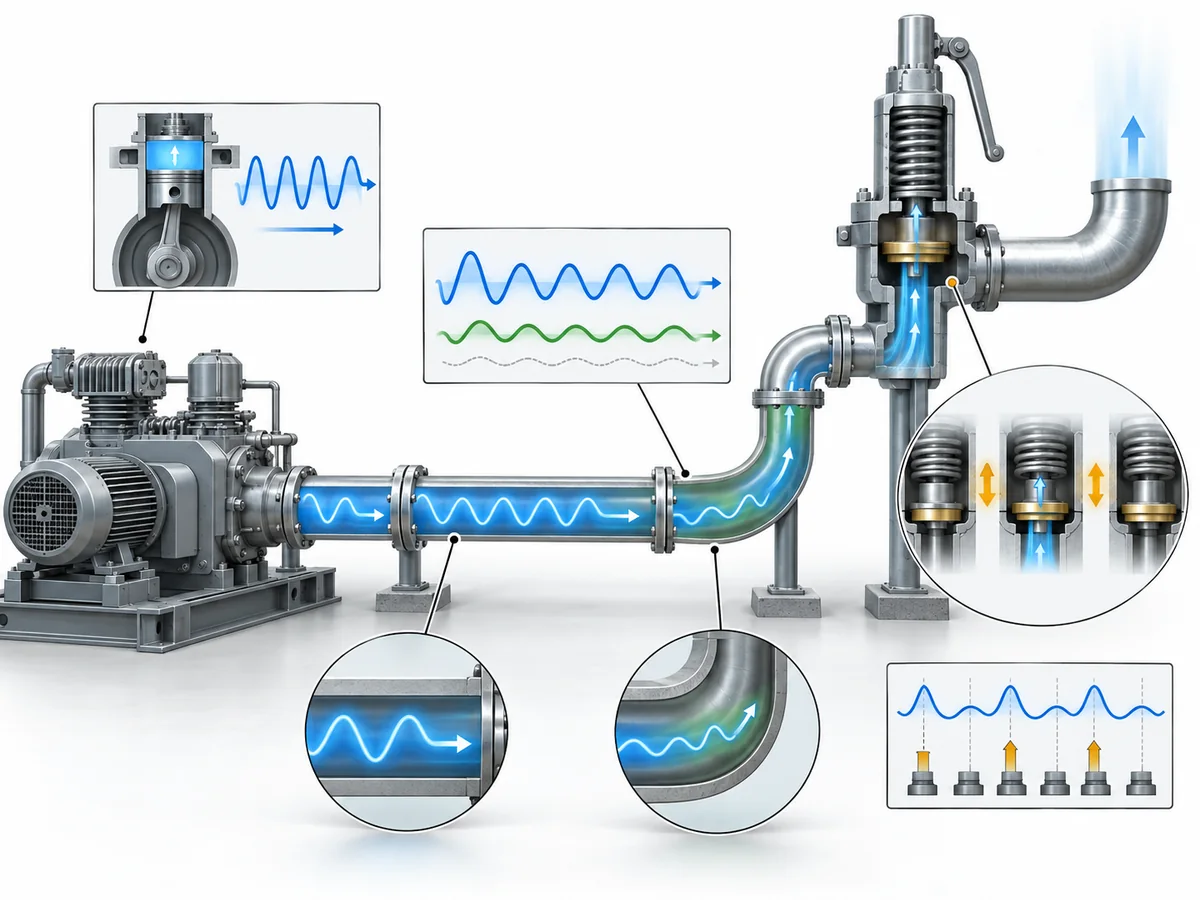
A compressor and its connected piping can produce time-varying pressure at the PRV inlet. That pressure history can matter to valve operation, but detecting pulsation does not prove that chatter will occur or that pulsation is the root cause of unstable motion.
This matters because PRV stability can depend on the valve, inlet piping, fluid, pressure system, and operating condition acting together. Peer-reviewed PRV dynamics research describes instability as a system-level interaction rather than a valve-only property.
A static inlet-pressure-loss check therefore answers only part of the installation question. It should not be treated as universal proof that every dynamic instability mechanism has been eliminated.
When pulsation is material, replace the vague question “Is this a pulsating compressor?” with a more useful one: What pressure history will this valve experience at its inlet, under which operating condition, and is that dynamic condition sufficiently defined to evaluate the candidate?
Useful engineering information may include the compressor type and operating case, the point where pressure is evaluated, the nature of the variation, and available pressure-trace, amplitude, or frequency information when relevant.
Compressor type must remain a qualifier. Evidence developed for reciprocating or other positive-displacement machinery should not automatically be generalized to every compressor design.
Pulsation also does not justify an automatic architecture decision. A particular spring-loaded or pilot-operated design may include features intended for specific transient conditions, but that is candidate-specific evidence, not proof that an entire architecture is inherently pulsation-proof.
If unstable valve movement has already been observed, the separate spring-loaded safety valve chatter guide covers diagnosis and corrective-action questions in more detail.
For candidate selection, work from the dynamic condition to the valve/system review: characterize the pressure behavior → distinguish the observed valve response from its possible cause → review the valve and inlet system together → verify the exact candidate.
Which Temperature Matters for Compressor Safety Valve Selection?
There is not one temperature value for every PRV selection check.
For relieving-capacity evaluation, start with the fluid temperature associated with the governing relieving condition. Normal compressor operating or discharge temperature is useful process information, but it should not automatically replace the temperature expected during the relief event.
| Temperature condition | What it helps verify | Common mistake |
|---|---|---|
| Relieving-fluid temperature | Capacity and process-service basis | Automatically using normal operating temperature |
| Maximum / minimum credible exposure | Body, trim, and material suitability | Checking only maximum temperature |
| Component temperature | Seat, seal, bellows, spring, or pilot limits | Checking the body rating only |
| Ambient / test condition where relevant | Environmental or test-setting treatment | Treating ambient as either universally decisive or irrelevant |
National Board guidance on pressure-relief-valve temperature considerations separates material, operating, and capacity effects rather than reducing temperature to one catalog rating.
A body temperature rating therefore does not automatically validate the seat, seal, spring, bellows, pilot, or accessory configuration. The limiting component may have a narrower operating envelope.
For some spring-loaded designs, elevated service temperature can also affect the relationship between ambient test conditions and intended in-service set pressure. Any cold differential test-pressure or temperature correction must follow the applicable manufacturer and configuration rather than being copied from another valve.
Low-temperature exposure deserves the same discipline. A candidate that is acceptable at the maximum temperature can still require separate material review if a credible operating or relief condition reaches materially lower temperatures.
For temperature review, work from the relief case outward: establish the relieving-fluid temperature → check capacity → establish the credible temperature envelope → verify the exact configuration.
For a deeper discussion of high-temperature materials, springs, seals, and valve configurations, see ZOBAI’s high-temperature safety valve guide.
How Does Back Pressure Change the Safety Valve Candidate?
Back pressure needs to be characterized before it can be used to screen valve architecture.
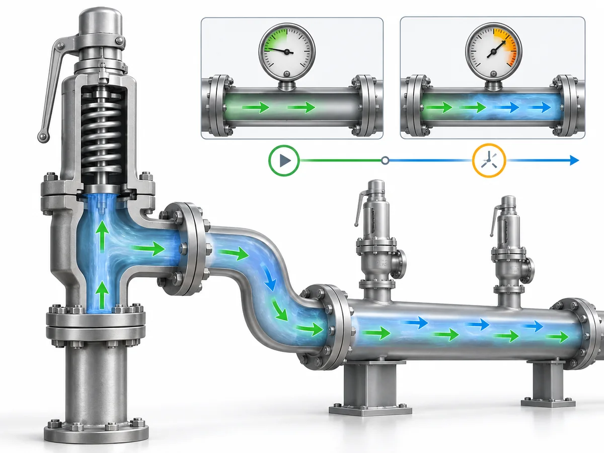
Superimposed back pressure exists at the PRV outlet before the valve opens. Built-up back pressure develops when relieving flow enters the downstream system. Superimposed back pressure may also be relatively constant or variable.
Those distinctions matter more than a generic Back Pressure = Yes field.
| Candidate architecture | Main question | What the architecture may address | What still requires verification |
|---|---|---|---|
| Conventional spring-loaded | What superimposed and built-up pressure will occur? | Some defined constant conditions may be accommodated by an appropriate design and setting treatment | Opening behavior, stability, capacity, model limit |
| Balanced bellows / piston | Does downstream pressure materially disturb force balance? | Balancing can reduce particular effects on opening behavior | Total back pressure, capacity, balancing-element limits, venting, temperature |
| Pilot-operated | How is the pilot/main valve referenced to downstream pressure? | Some designs can substantially reduce superimposed-pressure effects on opening | Model limit, capacity, pilot sensing/exhaust arrangement, reverse-flow conditions |
Manufacturer engineering guidance illustrates why these checks remain design- and configuration-specific. The Emerson Pressure Relief Valve Engineering Handbook, for example, treats back-pressure effects differently across conventional, balanced, and pilot-operated arrangements rather than assigning one operating envelope to every architecture.
A conventional valve should not automatically be rejected just because back pressure exists. Likewise, a balanced valve should not automatically be accepted simply because downstream pressure is high.
Balanced does not mean unlimited. A bellows or balanced piston addresses particular force-balance effects, while the complete valve still has finite pressure, temperature, and capacity limits.
Opening behavior and relieving capacity must also remain separate. A design can substantially reduce the influence of back pressure on opening pressure while available capacity still changes under the actual downstream condition.
The same boundary applies to pilot-operated valves. Some pilot arrangements manage superimposed back pressure effectively, but that does not make every pilot-operated valve independent of outlet pressure. Pilot sensing, exhaust routing, capacity behavior, exact allowable pressure, and reverse-flow conditions can remain relevant.
This is why a universal percentage ladder is unsafe. Rules that assign conventional, balanced, and pilot valves from one or two generic back-pressure percentages erase the conditions behind those numbers. The applicable limit can depend on the design, manufacturer, type of back pressure, fluid condition, applicable standard, and required capacity.
For detailed back-pressure mechanics and spring-loaded valve behavior, see ZOBAI’s back pressure in spring-loaded safety valves guide.
For candidate screening, start with the downstream condition: identify the pressure source → separate superimposed from built-up back pressure → determine variability → establish the relieving outlet condition → screen architecture → verify exact-model limits and capacity.
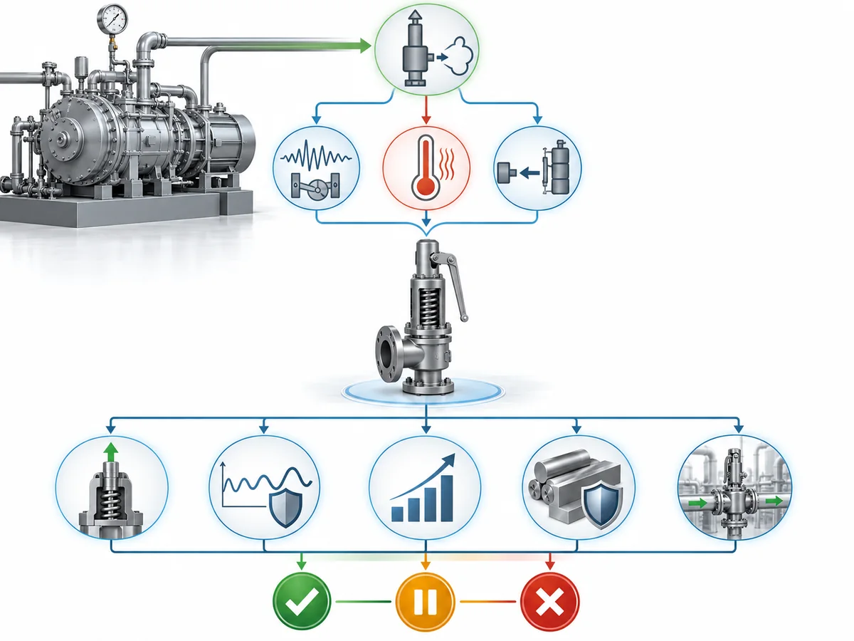
How Should Pulsation, Temperature and Back Pressure Be Evaluated Together?
Evaluate pulsation, temperature, and back pressure against one defined relief duty and one exact candidate.
Do not convert them into a formula that produces a valve architecture. Instead, use them to answer five engineering questions: whether the PRV will actuate as intended, whether dynamic operation is sufficiently understood, whether the exact configuration can pass the required load, whether every relevant component remains within its operating envelope, and whether the installed system preserves the assumptions used in selection.
This matters because three isolated catalog checks can all look acceptable while the overall candidate remains unresolved.
A balanced design, for example, may address an opening-force problem while capacity at the actual back pressure remains unverified. A valve may be inside its body temperature range while a seat or pilot seal becomes limiting. Static product conditions may be acceptable while material compressor/piping dynamics remain insufficiently characterized.
There are also real interactions between particular variables, but only where the evidence supports them. For some conventional spring-loaded configurations, service temperature and constant superimposed back pressure can both affect manufacturer-specific test-setting treatment. Back pressure can affect capacity even where its influence on opening-force balance has been reduced.
What should not be inferred is: pulsation + temperature + back-pressure percentage = spring / balanced / pilot. The evidence supports an integrated decision process, not a universal three-factor equation.
Product conformity remains separate from application suitability. ISO 4126-1 describes itself as a safety-valve product standard rather than an application standard.
| Screening outcome | Meaning in this article |
|---|---|
| PROCEED | Enough duty and candidate evidence exists to continue engineering or RFQ review |
| HOLD | An unresolved condition could materially change actuation, stability, capacity, or component compatibility |
| REJECT | A confirmed duty condition conflicts with a documented limit of the proposed candidate |
PROCEED, HOLD, and REJECT are engineering candidate-screening terms used in this article. They are not API, ASME, or ISO classifications, and PROCEED does not mean approved for service.
The decision is therefore not “which valve architecture sounds best?” It is: Does this exact candidate have enough evidence to remain on the shortlist for the defined compressor relief duty?
What Should Be Included in a Compressor Safety Valve RFQ?
A useful compressor safety valve RFQ should separate application requirements from supplier evidence.
The project defines what needs protection and what the PRV must do. The supplier then identifies an exact candidate and provides enough information to show how that candidate was selected.
| RFQ input | Why it matters | What the supplier should confirm |
|---|---|---|
| Protected duty and required capacity | Defines the protection task | Selected valve, sizing basis, capacity/orifice evidence |
| Fluid and relevant state | Affects sizing and compatibility | Suitability of the exact configuration |
| Operating and relieving conditions | Normal service may differ from the relief case | Pressure and temperature basis used |
| Pulsation data, when material | May change dynamic review | Whether further dynamic verification is needed |
| Superimposed / built-up back pressure | May change actuation, capacity, or architecture | Allowable back-pressure envelope and applicable corrections |
| Materials / compatibility | Body material alone may not define the complete valve | Body, trim, seats, seals, bellows, or pilot arrangement as applicable |
| Inlet / outlet interface | Connects the valve to the installed system | Connection size, rating, facing, and configuration |
| Project standards / documentation | Requirements vary by project and jurisdiction | Applicable calculations, test evidence, marking, and documents |
The exact thermodynamic inputs required should follow the actual fluid and sizing method rather than a universal checklist. Gas, liquid, steam, and two-phase duties do not necessarily require identical data.
Pulsation information should also be conditional. If pressure dynamics are material, a note saying pulsating service may be insufficient; available operating-case data or pressure traces can provide a clearer engineering basis. If pulsation is not material, there is no value in adding a complex dynamic-analysis requirement merely to make the RFQ look more complete.
Operating temperature and relieving temperature should be distinguished where they differ. Likewise, Back Pressure: Yes should be replaced with the downstream condition that actually needs review.
The supplier response should explain why the proposed candidate fits the defined duty, not just provide a model number. Depending on the project, that evidence can include the selected configuration and orifice, capacity basis, materials and sealing arrangement, applicable temperature/back-pressure limits, and significant assumptions or corrections used during selection.
Where certification, marking, testing, seat-tightness requirements, or specific documentation are part of the project specification, those requirements should be stated explicitly rather than assumed to apply to every compressor installation.
Existing valve documentation can support a replacement inquiry, but it is reference evidence rather than proof that the current relief duty is unchanged. A relief calculation, P&ID, system sketch, or relevant pressure record can reduce ambiguity where those documents already exist and are material to the review.
A useful RFQ handoff is: define the duty → provide relevant service and installed-system conditions → ask for the exact candidate → review the evidence and assumptions behind that selection.