Learn how MAWP, set pressure and required relieving capacity fit together when selecting a safety valve for a pressure vessel, with RFQ checks.

Selecting a safety valve for a pressure vessel is not a matter of matching one pressure number to a valve catalog. Three different engineering questions have to be answered: What pressure boundary protects the vessel? At what pressure should the relief device respond? How much flow must it relieve for the governing case?
Those questions correspond to MAWP, set pressure and required relieving capacity. They are related, but they belong to different parts of the pressure-protection problem.
A candidate can have an appropriate set pressure and still be unsuitable because its relieving capacity is inadequate, its capacity evidence does not apply to the actual service, or the installed inlet and outlet conditions have not been resolved.
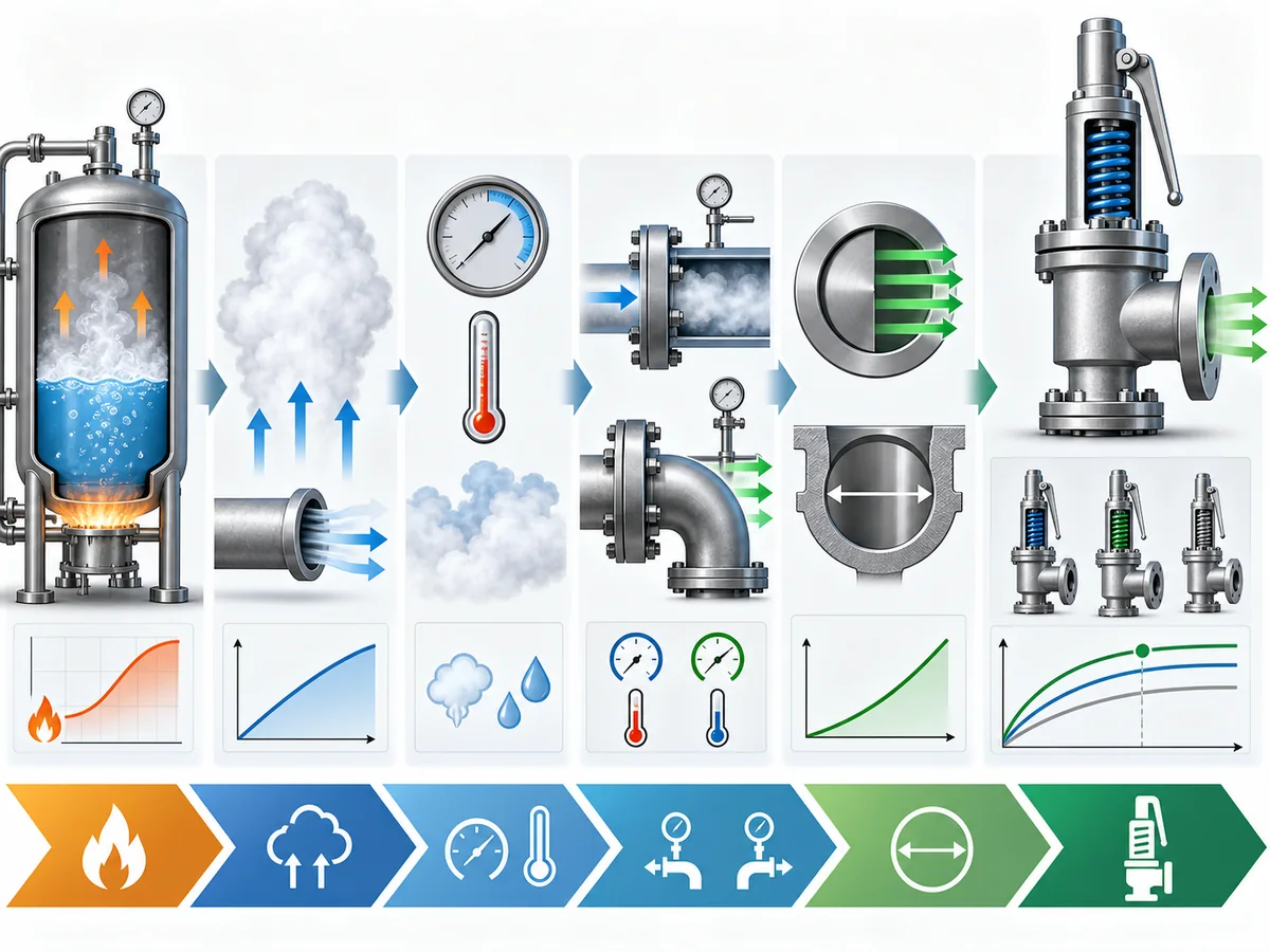
Use this sequence to keep the checks separate: vessel pressure basis → set-pressure basis → required relief duty → documented valve capacity → service and installation checks → engineering/RFQ review.
This guide focuses on that decision chain. It does not replace the governing pressure-vessel code, relief-load analysis or detailed safety-valve sizing. For broader application context, see pressure vessel safety valve applications.
Start with the Vessel: MAWP, Design Pressure and Operating Pressure
The first useful number is not the valve size. It is the documented pressure basis of the vessel being protected.
In ASME-oriented pressure-vessel terminology, maximum allowable working pressure (MAWP) is associated with the maximum permissible pressure of the completed vessel at the applicable coincident temperature. Emerson’s Pressure Relief Valve Engineering Handbook treats MAWP, design pressure and operating pressure as separate engineering terms; that same distinction is used here. Normal operating pressure and design pressure should not be substituted for MAWP simply because their numerical values happen to be close.
| Pressure term | Primary role in the decision | What it does not establish by itself |
|---|---|---|
| Operating pressure | Describes where the process normally operates | The vessel’s documented allowable pressure boundary |
| Design pressure | Forms part of the vessel design basis with the corresponding design temperature | The normal operating condition or required relieving capacity |
| MAWP | Defines the documented allowable pressure boundary of the completed vessel at the applicable temperature | The relieving load or required valve capacity |
The distinction matters because the valve-selection process inherits any error made here. Using current operating pressure as though it were MAWP can put the later set-pressure review on the wrong basis. Treating design pressure and MAWP as automatically interchangeable creates the same problem.
For an existing pressure vessel, start from the documented vessel data and governing design basis, not from an assumed relationship among the three numbers.
Temperature belongs with that review. National Board guidance on pressure-relief-valve application connects set-pressure evaluation with vessel MAWP while also noting the importance of temperature conditions.
MAWP is an essential pressure-protection input, but it does not tell you how much flow the valve must relieve. That question comes later.
How Set Pressure Relates to Vessel MAWP
Set pressure belongs to the pressure-relief device; MAWP belongs to the protected vessel.
For an ASME pressure-vessel application, the two have to be reviewed together. National Board guidance summarizes the general principle that at least one applicable pressure-relief valve is set at or below vessel MAWP, while the exact arrangement and pressure limits remain subject to the applicable Code rules.
That is more useful than memorizing an isolated percentage from a website or old datasheet.
| Term | What the reference is |
|---|---|
| Set pressure | The defined inlet-pressure point associated with the specified operating characteristic of the pressure-relief device |
| Overpressure | Pressure increase referenced to the valve set pressure |
| Accumulation | Pressure increase referenced to the vessel MAWP |
| Relieving pressure | Pressure at the relief device under the applicable relieving condition, including the relevant overpressure |
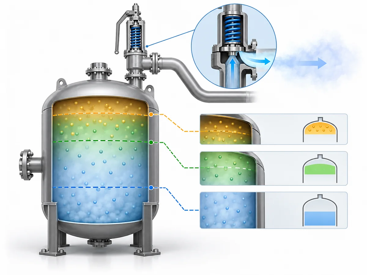
The difference between overpressure and accumulation is particularly important. They do not use the same reference pressure. If the relevant valve happens to be set at the vessel MAWP, their numerical values may coincide for that case, but the terms still describe different reference relationships.
The better engineering question is not “What percentage above MAWP can I use?” It is: For the governing vessel code, relief case and device arrangement, what set-pressure and allowable-pressure basis applies?
Current ASME BPVC Section XIII covers overpressure protection for pressurized equipment including pressure vessels and includes pressure-relief-device requirements, capacity certification and installation within its scope. The project-adopted code and edition still have to be confirmed rather than assumed from an article. For a broader standards overview, see the safety valve standards guide.
Passing this pressure-setting check is necessary. It is not the same as proving that the valve can relieve enough flow.
Why Correct Set Pressure Does Not Prove Adequate Capacity
A pressure vessel safety valve has to pass two different engineering checks.
| Check | Question |
|---|---|
| Pressure-setting compatibility | Does the candidate respond on the correct pressure basis for the protected vessel? |
| Capacity adequacy | Can the candidate relieve the required flow for the governing duty on the applicable service basis? |
A valve can pass the first check and fail the second.
Required relieving capacity belongs to the protected process or system. It represents what must be relieved for the applicable overpressure case.
Documented or certified relieving capacity belongs to the device. It represents what a particular valve design or configuration has demonstrated under defined rating or certification conditions.
For screening purposes, the comparison can be expressed as: required relieving capacity ≤ applicable documented valve capacity.
That inequality is not a complete acceptance rule. The two values have to refer to a compatible fluid, relieving condition and capacity basis, and the installed-system checks discussed later still have to be resolved.
The National Board NB-18 certification resource is useful here because it treats certified device types and certified relieving-capacity information as device evidence rather than as a substitute for application engineering.
The NB-18 Foreword further explains that listed capacity ratings come from tests of the relevant device type under defined conditions and that installation and operating conditions still have to be considered when selecting a device for service.
Connection Size Is Not Capacity Evidence
A nominal inlet size tells you how the valve connects mechanically. It does not by itself tell you the relieving capacity of the exact valve design.
The correct sequence is required duty first → capacity requirement second → candidate/device evidence third → connection and installation verification afterward.
If the set pressure is correct but the applicable capacity has not been demonstrated, the valve-selection decision remains incomplete.
How Required Relieving Capacity Is Established for the Vessel Duty
Required relieving capacity does not come from MAWP, vessel nozzle size or the size of the existing safety valve. It comes from the relief duty.
Work through the duty in this order:
-
Establish the governing relief scenario. Determine which credible condition creates the overpressure requirement for the protected vessel. Different scenarios can create different relief loads, so two vessels with the same MAWP do not necessarily require the same relieving capacity.
-
Establish the required relieving load. Once the applicable scenario is identified, determine how much flow has to be relieved for that case. This is the system-side requirement that the valve eventually has to meet.
-
Define the fluid and relieving state. Gas or vapor, steam, liquid and two-phase service do not automatically use the same sizing basis. Fluid composition and phase therefore belong to the calculation basis.
-
Establish the relieving conditions. Relieving pressure, relieving temperature and the physical-property inputs required by the selected sizing method have to be defined before required flow area or candidate capacity can be evaluated meaningfully.
-
Size against the established requirement. Only after the duty and relieving conditions are known can the applicable sizing procedure determine the required flow area and support comparison with candidate capacity.
Where API process-industry guidance applies, API 521 addresses pressure-relieving and depressuring systems and the analysis surrounding overpressure scenarios in facilities within its defined scope. It should not be treated as a universal vessel code outside that scope.
API 520 Part I is a sizing-and-selection standard for pressure-relieving devices within its defined refinery and related-industry scope. This guide stops before detailed equations, coefficients, effective-area calculations and final orifice selection.
For that next level of work, use the safety valve sizing guide.
MAWP defines a pressure boundary. The governing relief case establishes a flow requirement. Those are different engineering outputs.
Check the Installed Conditions Before Accepting the Capacity Match
Even when the candidate’s documented capacity is greater than the required capacity, the review is not finished. The capacity evidence has to apply to the actual service and installed system.
Fluid Phase and Relieving Conditions
First verify that the capacity basis is compatible with the actual fluid, phase, relieving pressure and relieving temperature.
A capacity value derived or certified under one condition should not be transferred to another service without the applicable engineering basis. This is one reason a datasheet line showing “capacity” should never be separated from the conditions under which that value applies.
Inlet-Side Conditions
A safety valve does not operate independently of the piping between the protected vessel and its inlet.
Inlet-system pressure loss and geometry can affect how the device behaves, so they have to be reviewed under the governing design and installation basis. This guide intentionally does not give one universal allowable inlet-loss percentage.
Where its scope applies, API 520 Part II treats pressure-relief-device installation as a separate engineering subject.
Outlet Back Pressure and Discharge Conditions
Emerson’s safety-relief-valve technical terminology distinguishes superimposed back pressure, which is present at the valve outlet before or when the device is called upon to operate, from built-up back pressure, which develops because of flow through the discharge system after the valve opens.
Those conditions can affect device behavior and the applicability of capacity data. Separately, the National Board NB-18 Foreword notes that capacity ratings established under atmospheric-discharge test conditions may not remain valid when discharge back pressure exists.
The selection question is not simply “Does the capacity number exceed my required flow?” It is: Does that capacity evidence apply to this fluid, this relieving condition and this installed inlet/outlet system?
For a deeper treatment of that installed-system issue, see back pressure and bellows.
What to Confirm Before Accepting a Safety-Valve Candidate or Sending an RFQ
At this point, an RFQ should no longer say only: “Need a safety valve for a pressure vessel at X pressure.” A supplier or responsible engineer needs enough information to review the same pressure-protection problem that produced the requirement.
Protected-Equipment Basis
- Protected vessel or equipment
- Documented MAWP or governing vessel pressure basis
- Design pressure where relevant
- Operating-pressure information
- Governing code and jurisdiction
- Relevant temperature basis
Relief-Duty Basis
- Applicable relief scenario
- Required relieving capacity
- Fluid or composition where necessary
- Phase or relieving state
- Relieving-pressure basis
- Relieving temperature and other required sizing inputs
Candidate and Installed-System Evidence
- Required set pressure or project setting basis
- Applicable documented or certified capacity
- Capacity medium or rating basis
- Project-required certification or documentation
- Inlet and outlet interface
- Inlet-system conditions
- Discharge destination and expected back pressure
- Service and material compatibility where required
The complete purchasing process may require additional commercial and documentation fields; those belong in the safety valve RFQ checklist. This section only covers the information needed to make the MAWP → set pressure → capacity decision usable.
The following terms are an article-specific engineering screening framework. They are not classifications defined by ASME, API or the National Board.
| Status | Engineering meaning |
|---|---|
| PROCEED | The reviewed inputs show no known mismatch, so the candidate can continue to detailed engineering or RFQ review. |
| HOLD | A decision-changing input or evidence item is unresolved; do not replace it with an assumption. |
| REJECT | A known candidate attribute conflicts with a known project requirement. |
An unknown required relieving capacity is a HOLD, not a reason to choose from flange size. A candidate whose applicable documented capacity is below the established requirement is a REJECT. A candidate that has no known mismatch after the available pressure, capacity and service checks may PROCEED to detailed engineering review.
PROCEED does not mean the valve is approved for installation, code-compliant for the project or finally accepted.
If the vessel basis, set-pressure basis, governing relief case, required capacity, fluid state and inlet/outlet conditions are ready, the next step is an engineering/RFQ review rather than selecting a valve from pressure and connection size alone.