A spring-loaded safety valve is a self-actuated pressure-relief device. A compressed spring supplies the closing force that holds the disc on the nozzle seat. Inlet pressure creates an opposing opening force. When the specified set-pressure condition is reached, the disc begins to lift and the valve discharges fluid from the protected system. The complete action …

A spring-loaded safety valve is a self-actuated pressure-relief device. A compressed spring supplies the closing force that holds the disc on the nozzle seat. Inlet pressure creates an opposing opening force. When the specified set-pressure condition is reached, the disc begins to lift and the valve discharges fluid from the protected system.
The complete action is more than “pressure overcomes the spring.” The valve must move from initial opening to stable lift, pass enough flow for the approved relief case and reseat after pressure falls. Disc geometry, the effective pressure area, spring compression, flow reaction, inlet loss, back pressure, blowdown adjustment, guide friction and piping all influence the actual motion.
Engineering takeaway: A spring-loaded valve works through a changing force balance. Set pressure begins the specified opening response; overpressure and flow forces develop lift; the valve relieves through its internal flow area; and the spring closes the valve only after pressure falls to the reseating condition.
60-Second Working Sequence
| Stage | What Happens | Main Engineering Concern |
|---|---|---|
| 1. Closed | The spring holds the disc against the nozzle seat. | Operating margin, seat condition and leakage. |
| 2. Pressure rises | Inlet-pressure force increases over the effective area. | Pressure fluctuation, simmer and test definition. |
| 3. Initial opening | The valve demonstrates its specified opening characteristic at set pressure. | Set-pressure basis, temperature and back pressure. |
| 4. Lift develops | Flow reaction and changing effective area can accelerate opening. | Valve design, overpressure, huddling chamber and stability. |
| 5. Relieving | Fluid passes through the nozzle, body and outlet. | Required capacity, orifice, inlet loss and outlet resistance. |
| 6. Pressure falls | Closing force becomes dominant as the system is depressurized. | Process pressure decay, back pressure and blowdown. |
| 7. Reseating | The disc returns to the seat at a pressure below set pressure. | Seat damage, guide friction, contamination and stable closure. |
Not every spring-loaded valve “pops” in exactly the same way. Opening characteristics vary with gas, steam or liquid service, valve geometry, lift design and the applicable product standard. Use manufacturer-certified data for the actual model.
What Is a Spring-Loaded Safety Valve?
A spring-loaded safety valve is a direct-acting pressure-relief device that uses a mechanical spring to hold the main disc closed. The protected-system pressure supplies the energy for automatic opening. The basic safety action does not require an external actuator, electrical power or control signal.
Spring-loaded designs are used on pressure vessels, boilers, steam systems, air receivers, compressors, process skids, gas systems and suitable liquid duties. They may be conventional, balanced bellows, full lift, low lift, open bonnet, closed bonnet or another manufacturer-specific configuration.
The terms safety valve, relief valve, PSV and PRV can vary by industry. For terminology, use PRV vs PSV vs Safety Valve vs Relief Valve.
Working-Principle Question
How do spring force, inlet pressure and flow reaction move the disc?
Selection Question
Can the specific model handle the required capacity, medium, temperature and installed conditions?
Direct-acting boundary: “Spring-loaded” describes the main closing mechanism. It does not identify whether the valve is conventional or bellows-balanced, full lift or low lift, metal-seated or soft-seated, open-bonnet or closed-bonnet. Those construction details change back-pressure response, temperature limits, leakage behavior and maintenance requirements.
This article answers the first question. For the second, use How to Select Spring-Loaded Safety Valves.
Main Parts of a Spring-Loaded Safety Valve
| Part | Main Function | Typical Performance Risk |
|---|---|---|
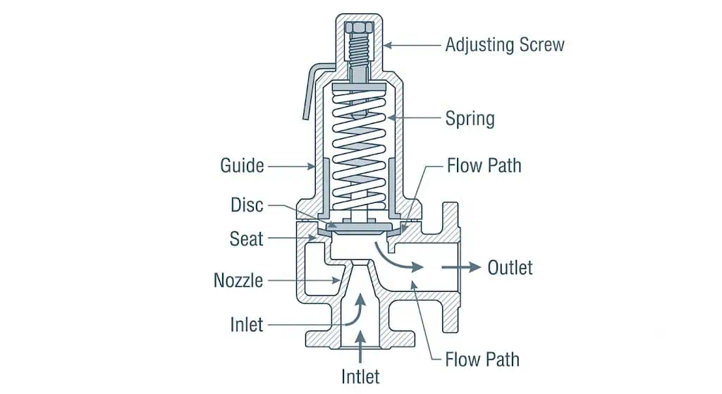
| Body | Contains the internal flow path and connects the inlet to the outlet. | Pressure rating, erosion, corrosion and piping load. |
| Nozzle | Forms the inlet throat and precision seating edge. | Erosion, incorrect flow area, damaged seat and deposits. |
| Disc | Closes the nozzle and lifts to create the relieving flow path. | Misalignment, vibration damage, sticking and seat damage. |
| Disc holder / huddling geometry | Transmits motion and may use flow forces to promote opening. | Incorrect assembly, deposits or altered dynamic behavior. |
| Guide | Maintains controlled axial movement. | Friction, corrosion, galling, fouling and poor reseating. |
| Spindle | Transfers spring force to the disc assembly. | Bending, misalignment, friction and assembly error. |
| Spring | Supplies closing force and supports the calibrated set pressure. | Wrong range, corrosion, relaxation, temperature exposure and unauthorized adjustment. |
| Spring washers | Transmit and distribute spring load. | Incorrect assembly or damaged bearing surfaces. |
| Adjusting screw | Changes spring compression during controlled calibration. | Unauthorized set-pressure change and broken traceability. |
| Blowdown ring(s), where fitted | Modify local flow geometry and opening/reclosing behavior. | Incorrect position, unrecorded adjustment and unstable operation. |
| Bonnet and cap | Protect the spring and adjustment mechanism. | Wrong venting, corrosion and environmental exposure. |
| Lifting device, where fitted | Allows controlled manual lift for specified applications. | Unsafe discharge, seat damage and misuse. |
| Seat or resilient seal, where fitted | Provides the final closed interface between the disc and nozzle. | Temperature limit, chemical attack, compression set, contamination and post-lift leakage. |
| Bellows, in a balanced design | Reduces specified outlet-pressure force effects and may isolate the guide or spring chamber from process fluid. | Fatigue, corrosion, leakage, blocked bonnet vent and loss of balancing function. |
Design variation: Not every valve contains the same parts or adjustment features. Some have one or more blowdown rings; others use fixed geometry. Some use open bonnets for steam, while others use closed bonnets. Follow the manufacturer drawing for the actual valve.
Component-level material review: Body material alone does not establish service suitability. Nozzle, disc, guide, spindle, spring environment, bellows, gasket and soft-seat materials can control corrosion, galling, sticking, leakage and useful life.
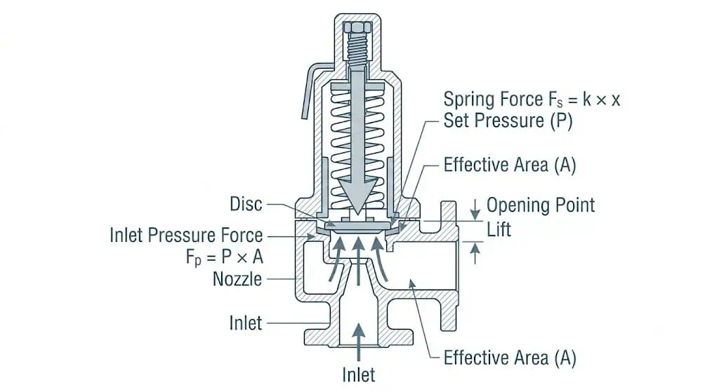
The Simplified Force Balance
The principle can be introduced with two basic relationships:
Spring force: Fs ≈ Fpreload + kx
Pressure force: Fp ≈ Pin × Aeffective
Where:
- Fs is the spring-generated closing force;
- Fpreload is the initial spring load established during calibration;
- k is the effective spring rate;
- x is additional spring compression as the disc moves;
- Pin is inlet pressure;
- Aeffective is the effective pressure area.
While the valve is closed, spring load and other closing forces exceed the net opening force. As inlet pressure rises, pressure force increases. At the specified set-pressure condition, the force balance and valve geometry permit the initial opening response.
Qualitative net motion: Fnet ≈ pressure forces + flow-reaction forces − spring force − friction and resisting forces
For a conventional valve connected to a pressurized outlet, the outlet-side pressure force must also be considered. The effective areas are geometry-dependent and can change as the disc lifts. This is why a bench set-pressure result cannot by itself predict installed lift, blowdown or stability.
These equations do not size the valve. Capacity calculations require the applicable gas, steam, liquid or two-phase method, certified coefficients and relieving conditions.
Why Opening Is More Than a Static Force Balance
After the disc begins to lift, the exposed pressure area and local flow pattern can change. High-velocity fluid acts on the disc holder, huddling chamber or related geometry and can create additional opening force. In a pop-action design, this feedback promotes rapid movement toward a larger lift.
At the same time:
- the spring compresses further and produces greater closing force;
- flow momentum creates forces on the disc assembly;
- inlet pressure can fall because of inlet-line resistance;
- outlet pressure can rise because of discharge-system resistance;
- the process pressure source may continue adding mass or energy;
- disc inertia and guide friction influence motion.
The operating point is therefore dynamic. Stable lift requires the valve, relief load and connected piping to work as one system.
Compressible-service valves may use pop-action geometry to develop rapid lift, while liquid-service designs may open more proportionally. Steam behavior also depends on the applicable valve design and test definition. The words “pop,” “proportional” and “full lift” should therefore be tied to the actual certified model rather than used as universal descriptions.
Huddling Chamber and Blowdown Adjustment
Many spring-loaded safety valves use a huddling chamber, disc-holder profile or blowdown ring to control how flow forces develop. These features can influence rapid opening, lift and closing behavior.
Do not move a blowdown ring as a casual field adjustment. Its position can change opening and reseating behavior. Adjustment should follow the manufacturer’s procedure, authorized calibration controls and documented final settings.
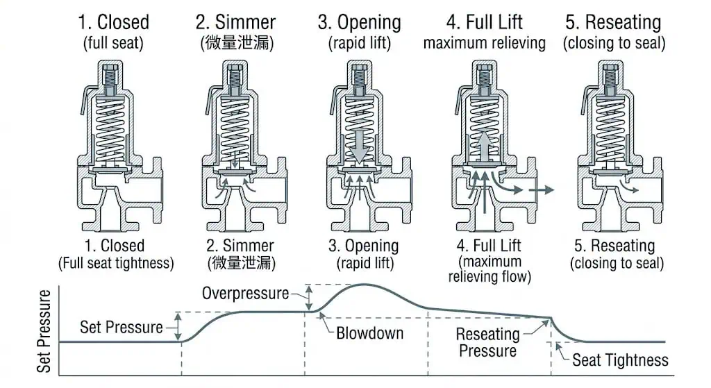
The Seven-Stage Working Cycle
-
Closed during normal operation.
Spring preload keeps the disc seated. Tightness depends on seat condition, alignment, operating margin, temperature and medium cleanliness. -
Pressure approaches the set condition.
The net opening force increases. Depending on design and service, small leakage or simmer may appear before decisive lift. -
The specified opening characteristic occurs.
Set pressure is established according to the applicable test definition. It should not be reduced to one universal phrase such as “first visible movement.” -
Flow forces develop lift.
As the flow path opens, pressure and momentum act on a larger or different effective area. Pop-action designs may accelerate rapidly toward higher lift. -
The valve relieves the required flow.
Fluid passes through the internal orifice and outlet. Certified capacity is associated with defined pressure, fluid and test conditions. -
System pressure falls.
As the relief source is controlled or inventory is discharged, opening forces reduce. Spring force becomes dominant, subject to back pressure and dynamic effects. -
The valve reseats.
The disc returns to the nozzle at the reseating pressure. The difference between set pressure and reseating pressure is blowdown.
Set Pressure, Overpressure, Relieving Pressure and Blowdown
| Term | Meaning in the Working Cycle | Common Misunderstanding |
|---|---|---|
| Operating pressure | Normal process pressure while the valve should remain closed. | It is treated as acceptable to run continuously at set pressure. |
| Set pressure | The inlet pressure associated with the specified opening characteristic under defined test conditions. | It is treated as proof of full capacity. |
| Overpressure | Pressure rise above set pressure during relief. | It is treated as routine operating margin. |
| Accumulation | Pressure increase above the protected equipment’s MAWP or other allowable boundary during an overpressure event. | It is treated as another name for overpressure without reference to the equipment boundary. |
| Relieving pressure | The pressure condition used for capacity determination. | It is assumed to be identical to set pressure. |
| Reseating pressure | The pressure at which the valve closes after relieving. | It is assumed to equal set pressure. |
| Blowdown | The difference between set and reseating pressure. | It is treated as an arbitrary spring adjustment. |
| Seat tightness | Leakage performance while the valve is closed. | It is treated as proof of capacity or stability. |
| CDTP, where applicable | Cold differential test pressure used to account for service temperature or back-pressure effects during controlled calibration. | It is treated as permission to change the operating set pressure without an approved basis. |
| Back pressure | Pressure at the outlet before opening or developed while the valve relieves. | It is assumed to affect only outlet piping and not the valve force balance. |
Use Safety Valve Set Pressure, Overpressure, Accumulation and Blowdown for detailed definitions, formulas and CDTP discussion.
How a Spring-Loaded Valve Relieves Capacity
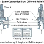
The valve protects equipment only when its available relieving capacity is adequate for the governing scenario. The inlet connection size does not determine this capacity.
Capacity depends on:
- internal flow area or certified orifice;
- set and relieving pressure;
- gas, steam, liquid or two-phase condition;
- relieving temperature and fluid properties;
- valve lift and discharge coefficient;
- back pressure and applicable correction basis;
- manufacturer-certified configuration.
Required Relieving Capacity
The flow produced by the approved overpressure scenario.
Certified or Documented Capacity
The valve performance established under stated conditions for the identified design.
A valve can open at the correct set pressure and still be undersized. The set-pressure test checks an opening characteristic; it does not recreate the full emergency relief load.
| Evidence | What It Demonstrates | What It Does Not Demonstrate |
|---|---|---|
| Set-pressure certificate | Opening adjustment under the stated test medium and conditions | Full emergency capacity, installed stability or correct relief scenario |
| Certified or accepted capacity data | Supported flow performance for an identified valve, orifice and basis | That the buyer’s required relief load was calculated correctly |
| Connection size and pressure class | Mechanical interface and pressure-temperature envelope | Effective flow area or relieving capacity |
| Seat-tightness report | Closed-valve leakage under a stated test method | Set-pressure accuracy, blowdown, capacity or chatter resistance |
Use the Safety Valve Sizing and Certified Relieving Capacity Guide for the sizing workflow.
Conventional and Balanced Spring-Loaded Behavior
In a conventional spring-loaded valve, outlet pressure can act on internal areas and influence the net force balance. The effect depends on the valve geometry and whether the back pressure exists before opening or develops during flow.
A balanced bellows design adds a bellows arrangement intended to reduce the influence of outlet pressure on the force balance within the manufacturer’s limits. It remains a spring-loaded valve, but adds bellows material, fatigue, venting and failure-mode considerations.
Superimposed Back Pressure
Outlet pressure present before the valve opens. It may be constant or variable and can shift the net opening condition of a conventional design.
Built-Up Back Pressure
Outlet pressure generated by relieving flow through the discharge system. It can reduce lift, change blowdown and contribute to chatter or poor reseating.
A balanced bellows reduces specified outlet-pressure force effects; it does not eliminate outlet-system pressure drop, capacity correction, discharge reaction, drainage, bellows fatigue or the need for an open and correctly routed bonnet vent.
| Configuration | Force-Balance Characteristic | Additional Review |
|---|---|---|
| Conventional spring-loaded | Outlet pressure may influence opening, lift and reseating. | Superimposed and built-up back pressure, bonnet condition and capacity basis. |
| Balanced bellows spring-loaded | Bellows reduces outlet-pressure influence on specified internal areas. | Bellows limits, material, fatigue, bonnet vent and failure consequence. |
For the full system review, use How Back Pressure Affects Safety Valve Performance and Back Pressure and Bellows Engineering Hub.
What Changes Installed Performance?
| Factor | Effect on the Working Cycle | Possible Result |
|---|---|---|
| Operating pressure too close to set pressure | Reduces the closing-force margin during normal fluctuations. | Simmer, leakage or nuisance lifting. |
| Excessive inlet pressure loss | Pressure at the valve inlet falls after flow begins. | Chatter, cycling and reduced stable lift. |
| Superimposed back pressure | Changes the outlet-side force condition before opening. | Opening shift or instability in sensitive designs. |
| Built-up back pressure | Raises outlet pressure while the valve is flowing. | Reduced lift, chatter, capacity concern or poor reseating. |
| Oversizing | Actual flow demand may be too low for stable high lift. | Flutter, chatter and repeated seat impact. |
| Dirty or sticky medium | Increases seat leakage and moving-part friction. | Sticking, delayed opening or poor reseating. |
| Corrosion | Changes seat, guide, spring or pressure-boundary condition. | Leakage, drift, restricted motion or failure. |
| Temperature | Affects spring load, material strength, clearances and seats. | Calibration error, leakage or shortened service life. |
| Piping load or misalignment | Can distort the body or moving-part alignment. | Seat leakage and guide friction. |
| Incorrect spring range or high spring temperature | Changes available preload, spring rate or long-term spring condition. | Set-pressure drift, unstable adjustment or reduced service life. |
| Incorrect blowdown-ring position | Changes local flow forces during opening and closing. | Excessive blowdown, short cycling, chatter or delayed reseating. |
| Liquid or condensate trapped in the outlet | Adds variable outlet resistance and dynamic reaction. | Water hammer, unstable lift, seat impact and post-event leakage. |
| Unsupported discharge piping or excessive reaction load | Transfers force and bending into the valve body and nozzle connection. | Misalignment, flange leakage, body distortion and guide friction. |
Use the Safety Valve Installation Guide for inlet, outlet, drainage, support and commissioning checks.
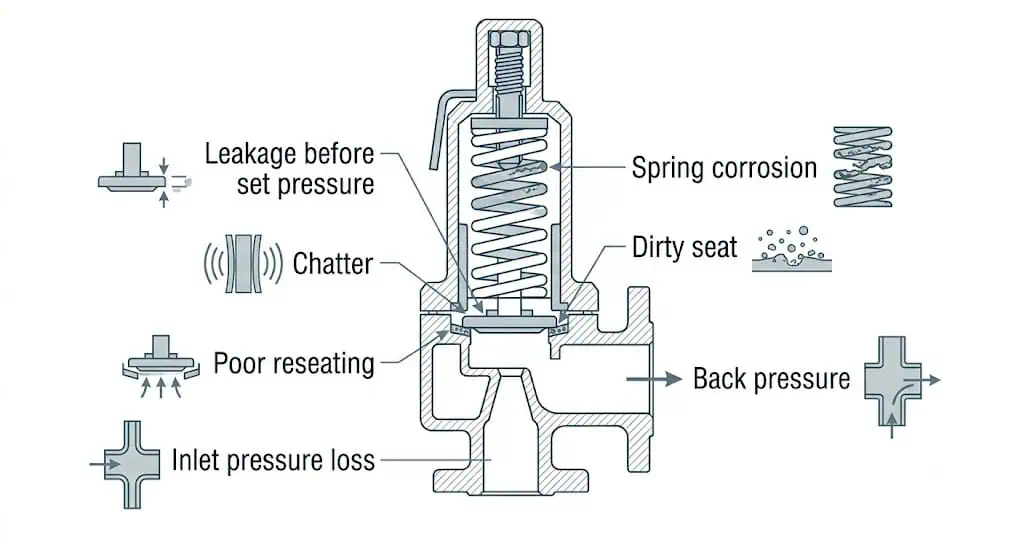
Common Problems and What They Usually Mean
| Symptom | Possible Causes | Review Before Repair |
|---|---|---|
| Leaks below set pressure | Low operating margin, contamination, seat damage, corrosion, thermal distortion or piping stress | Pressure trend, seat condition, alignment, medium and calibration record |
| Chatters during relief | Inlet loss, built-up back pressure, oversizing, process instability or unsuitable blowdown | Relief load, inlet/outlet hydraulics, valve size and pressure history |
| Opens but pressure continues rising | Insufficient capacity, wrong relief scenario, incomplete lift, blocked outlet or excessive back pressure | Required load, certified capacity, fluid phase and discharge path |
| Does not reseat cleanly | Seat damage, guide friction, contamination, back-pressure fluctuation or unsuitable closing behavior | Internals, outlet pressure, blowdown and process pressure decay |
| Set pressure changes after repair | Wrong spring, assembly change, seat work, missing service correction or uncontrolled adjustment | Parts, calibration basis, CDTP, seals, tags and records |
| Does not open at the expected test pressure | Wrong spring, incorrect CDTP basis, blocked inlet, guide friction, damaged adjustment or test-method mismatch | Nameplate, service correction, test medium, spring identification, inlet path and calibration procedure |
| Opens and immediately slams shut | Excessive inlet loss, insufficient flow demand, oversizing, liquid outlet load or unstable pressure source | Dynamic inlet pressure, required flow, outlet drainage, valve lift and piping layout |
As-found data first: Record leakage, set pressure, blowdown-ring position, spring identification, seat condition, deposits and installation observations before cleaning or adjustment. Otherwise the repair may remove the evidence needed to identify the real failure mechanism.
Do not tighten the adjusting screw to stop leakage. Raising the set pressure may hide the symptom while reducing the intended protection. Diagnose the seat, operating pressure, installation and calibration basis first.
Illustrative Case: Correct Bench Test, Unstable Installed Operation
Fictional training example — not field data
Situation
- spring-loaded gas safety valve;
- set pressure verified on a test stand;
- valve connected to a longer outlet line and common header after a plant modification;
- rapid opening followed by repeated impact and vibration during relief.
Why the Spring Was Not the First Suspect
The test stand confirmed the opening setting under its test conditions. It did not reproduce the installed inlet loss, built-up back pressure, header pressure and mechanical response of the modified piping.
Engineering Review
- recalculate the required relief load and valve operating range;
- calculate inlet pressure loss and outlet back pressure;
- confirm the manufacturer’s allowable back-pressure basis;
- check whether the valve is oversized for the governing case;
- inspect the disc, seat and guide for chatter damage;
- review a balanced design or piping modification if justified.
Lesson: The spring initiates and controls the mechanical response, but installed stability belongs to the complete pressure-relief system.
Composite engineering example — not project design data
Correct Set Pressure, Insufficient Relieving Capacity
Problem: A replacement valve opened at the specified set pressure, but protected-equipment pressure continued to rise during the governing event.
Cause: The replacement matched the inlet connection and pressure class but used a smaller effective orifice. Its supported capacity was below the approved required relieving load.
Correction / prevention: Reconfirm the relief scenario and compare required capacity with the identified valve’s certified or accepted capacity. Do not raise set pressure or infer capacity from connection size.
Composite engineering example — not project design data
High-Temperature Steam Caused Early Leakage and Set-Pressure Drift
Problem: A steam valve required repeated seat work and showed inconsistent as-found settings after service.
Cause: The spring environment, seat construction and trim materials had not been reviewed for the actual steam temperature and condensate condition. Thermal exposure and corrosion affected the spring, guide and seating surfaces.
Correction / prevention: Verify the relieving temperature, bonnet arrangement, spring and trim material limits, drainage and any cold differential test pressure correction before calibration and return to service.
Composite engineering example — not project design data
Valve Reassembled After Repair Without Controlled Recalibration
Problem: A repaired valve was returned to the line with a clean seat but later opened away from the required setting.
Cause: Seat machining, replacement parts and spring compression changed the assembly, but no traceable final calibration, tagging or resealing was completed.
Correction / prevention: Treat seat work, spring replacement, internal-part changes and blowdown-ring movement as controlled repair activities. Perform the required pressure-boundary, set-pressure and seat-tightness tests, record the final settings and restore the required seal and identification.
When Is a Spring-Loaded Safety Valve a Good Starting Point?
A spring-loaded design is often a practical starting point when:
- the service is steam, air, gas or a suitable liquid duty;
- the medium and deposits will not prevent reliable movement;
- the required capacity is available in the selected model;
- the back-pressure condition is within the design limits;
- the operating pressure provides suitable margin below set pressure;
- the plant can inspect, calibrate and repair the valve correctly;
- a direct mechanical device is preferred for lifecycle simplicity.
Extra review is required for:
- high or variable back pressure;
- dirty, polymerizing, crystallizing or sticky medium;
- very close operation to set pressure;
- two-phase or flashing flow;
- high temperature or cryogenic service;
- corrosive or toxic discharge;
- repeated cycling or severe vibration.
When a pilot-operated design enters the review: Consider a pilot-operated valve when supported manufacturer data shows an advantage for the operating margin, pressure level, required capacity or back-pressure condition. Do not assume it is automatically better for dirty, wet, polymerizing, crystallizing or particle-containing service; small pilot passages and sensing lines can become the controlling reliability risk.
Use How to Select Spring-Loaded Safety Valves for detailed selection and Spring-Loaded vs Pilot-Operated Safety Valves for the design comparison.
Adjustment, Testing and Maintenance Boundary
The working principle may appear simple, but the adjustment and repair controls are safety-critical.
Use the approved set-pressure and test procedure
Confirm the correct spring range and part identification
Apply documented service corrections or CDTP where required
Use traceable test instruments
Record the opening characteristic and final setting
Perform seat-tightness testing when specified
Seal and tag the final adjustment
Record blowdown-ring positions where applicable
Match the test report to the valve serial number
Reinspect installation after repeated chatter or piping modification
Return-to-Service After Repair or Internal Adjustment
- Preserve as-found evidence.
Record the valve identity, set pressure, leakage, ring positions, spring and internal condition before cleaning or machining. - Control parts and repair scope.
Verify the spring range, nozzle, disc, guide, spindle, bellows, gaskets and soft-seat materials against the approved configuration. - Reassemble to the manufacturer procedure.
Control alignment, clearances, torque and any blowdown-ring setting. - Repeat the required tests.
Perform pressure-boundary testing, set-pressure calibration, blowdown or functional checks and seat-tightness testing as required by the governing route. - Restore traceability.
Match reports to the serial number, record replacement parts and final settings, then restore tags, locks and seals. - Verify the installation cause.
If the valve chattered, leaked after lift or suffered repeated damage, inspect inlet loss, back pressure, supports and drainage before reinstalling the same configuration.
Where the owner, jurisdiction or repair route requires National Board authorization, confirm that the repair organization holds the appropriate VR scope. VR authorization addresses controlled pressure-relief-valve repair; it does not replace the owner’s application, installation and operating review.
API 527 may be specified for seat-tightness testing, but it does not prove capacity, correct set-pressure selection or stable installation. See the API 527 Seat Tightness Test Guide.
For inspection intervals, repair scope and return-to-service controls, use the Safety Valve Maintenance and Inspection Guide.
RFQ and Replacement Data for a Spring-Loaded Safety Valve
| Data Group | Information to Provide |
|---|---|
| Protected equipment | Equipment type, tag, MAWP/design basis and applicable code. |
| Relief case | Governing scenario, required capacity, units and calculation revision. |
| Pressure data | Operating, set, relieving and downstream pressure conditions. |
| Medium | Composition, gas/steam/liquid/two-phase state, cleanliness and hazards. |
| Temperature | Operating and relieving temperature, plus environmental limits. |
| Valve construction | Conventional, balanced bellows, full lift, bonnet and lifting-device requirements. |
| Connections | Inlet/outlet size, rating, facing, thread, orientation and dimensional limits. |
| Materials | Body, nozzle, disc, guide, spring, bellows, seat and seal requirements. |
| Installation | Inlet line, outlet line, back pressure, drainage, support and discharge destination. |
| Documents | Datasheet, capacity evidence, material certificates, calibration, pressure and leakage reports. |
| Operating behavior | Pressure pulsation, expected lifting frequency, operating margin, previous leakage or chatter history. |
| Replacement evidence | Old nameplate, serial number, orifice, certified capacity, spring identification, repair history and as-found condition. |
| Testing and repair route | Test medium, CDTP basis, seat-tightness method, witness points, seal/tag requirements and VR route where applicable. |
Need a Spring-Loaded Safety Valve Review?
Send the protected equipment, medium, set pressure, required capacity, relieving temperature, back pressure, connections, materials and document requirements.
Upload Valve Data View Spring-Loaded Safety Valves Request a QuoteStandards and Authoritative References
The applicable standard depends on the protected equipment, service, jurisdiction and project specification. A product-standard name does not replace the actual relief calculation or manufacturer-certified data.
| Reference | Role in This Topic | Link |
|---|---|---|
| ASME BPVC Section XIII | Overpressure-protection rules and pressure-relief-device requirements under the ASME framework | ASME official page |
| ASME BPVC Section I | Power-boiler construction and safety-valve context where boiler service is within scope | ASME BPVC overview |
| ASME BPVC Section VIII, Division 1 | Pressure-vessel construction and pressure-relief-device context where applicable | ASME official page |
| API 520 Part I, 10th Edition | Sizing and selection of pressure-relieving devices within its refinery and process-industry scope | API official page |
| API 520 Part II, 7th Edition | Installation and engineering analysis of pressure-relieving-device installations within its scope | API official page |
| API RP 576, 5th Edition | Inspection, testing and repair practices for pressure-relieving devices in applicable process-industry service | API inspection training page |
| API 527 | Seat-tightness testing for applicable pressure-relief valves; not sizing or installed-system validation | API official publication preview |
| ISO 4126-1:2013 | General product requirements for safety valves irrespective of fluid | ISO official page |
| National Board VR / NBIC | Authorized pressure-relief-valve repair framework where adopted or required | National Board VR page |
Standards boundary: ASME equipment sections, Section XIII, API 520, API RP 576, API 527, ISO 4126 and NBIC/VR serve different purposes. Verify the adopted edition, jurisdiction, legal manufacturer or repair organization, model, marking, capacity certificate and repair scope. A generic standards list is not evidence that the supplied valve is acceptable for the actual application.
FAQ About How Spring-Loaded Safety Valves Work
How does a spring-loaded safety valve work?
A compressed spring holds the disc on the nozzle seat. Rising inlet pressure increases the opening force. At the specified set-pressure condition the disc begins to lift, flow forces develop further opening, the valve relieves fluid and the spring reseats the disc after pressure falls.
Is a spring-loaded safety valve automatic?
Yes. It is self-actuated by process pressure for its basic safety action and does not require external electrical power or an actuator.
Does the valve fully open exactly at set pressure?
Not necessarily. Set pressure identifies the specified opening characteristic. Additional pressure rise and flow forces may be needed to develop the lift associated with rated or certified capacity.
What causes a spring-loaded safety valve to pop open?
In pop-action designs, initial lift exposes flow-reactive geometry such as a huddling chamber or disc-holder area. The resulting fluid force can rapidly increase lift. The exact action is design-specific.
What is blowdown in a spring-loaded safety valve?
Blowdown is the difference between set pressure and reseating pressure. It describes how far system pressure falls before the valve closes.
Why can the valve leak before set pressure?
Possible causes include inadequate operating margin, seat contamination, damaged seating surfaces, corrosion, thermal distortion, piping stress or poor repair.
Why does a spring-loaded safety valve chatter?
Common causes include excessive inlet pressure loss, built-up back pressure, valve oversizing, unstable process pressure and unsuitable valve or piping conditions.
Does set pressure prove that the valve has enough capacity?
No. Set pressure confirms an opening characteristic. Required capacity must be compared with the manufacturer’s certified or documented capacity under the stated relieving conditions.
What is the difference between conventional and balanced spring-loaded valves?
A conventional valve can be influenced by outlet pressure acting on internal areas. A balanced bellows design uses a bellows to reduce that influence within the manufacturer’s specified limits.
Can the adjusting screw or blowdown ring be changed in the field?
They should not be changed casually. Adjustment should follow engineering approval, manufacturer procedures, controlled calibration, final sealing, tagging and documentation.
What information is needed to select a spring-loaded safety valve?
Provide the protected equipment, relief scenario, MAWP, operating and set pressure, required capacity, medium and phase, relieving temperature, back pressure, connections, materials and required certificates.
What is the difference between set pressure and overpressure?
Set pressure identifies the specified opening response. Overpressure is the pressure increase above set pressure while the valve is relieving and developing the lift needed for flow.
How does back pressure affect a spring-loaded safety valve?
Back pressure can change the net force balance, lift, effective capacity, blowdown and reseating. Conventional valves are generally more sensitive; balanced bellows designs reduce specified force effects within manufacturer limits.
Why is certified relieving capacity more important than connection size?
Connection size only identifies the mechanical interface. Certified or accepted capacity is tied to the valve design, effective orifice, pressure, fluid and test basis and must be compared with the required relief load.
Can a spring-loaded safety valve be used for dirty or sticky fluid?
Sometimes, but deposits, polymer, crystals, coke, solids or viscous material can foul the seat, restrict the inlet and increase guide friction. The service and maintenance strategy require explicit manufacturer review.
When should a pilot-operated safety valve be considered instead?
A pilot-operated design may be considered when supported data shows an advantage for operating margin, pressure, capacity or back pressure. Pilot passages, sensing lines, seals, exhaust and service cleanliness must also be suitable.
How often should a spring-loaded safety valve be inspected or recalibrated?
There is no universal interval. Use the applicable code and owner program, service severity, operating margin, corrosion or fouling risk, lift history, prior as-found results and manufacturer instructions.
What must be checked after a spring-loaded valve is repaired?
Verify parts and spring identity, internal alignment, blowdown-ring settings, pressure-boundary integrity, set pressure, required seat tightness, serial-number traceability, final tags and seals, and the installation cause of any previous damage.
Understand the Working Principle—Then Verify the Real Duty
Send the relief calculation, medium, set pressure, required capacity, relieving temperature, back pressure and piping information for a spring-loaded safety valve review.
Upload Engineering Data Request a Spring-Loaded Safety Valve Quote