Learn why storage tanks collapse under vacuum, how protection systems can fail, and what engineers should verify before changing vacuum protection.

A storage tank can collapse under vacuum when pressure inside the tank falls far enough below the pressure outside that the resulting differential exceeds the tank’s actual external-pressure capability. The tank does not need to approach a perfect vacuum before damage becomes possible.
The failure usually develops as a chain rather than as a single bad component. An operating or thermal event first creates an inbreathing demand—the need for gas to enter the tank as internal pressure falls. The protection system must then admit enough gas, through an available and sufficiently unrestricted path, before the pressure differential becomes damaging.
That means a collapsed tank does not automatically prove that the vacuum valve itself failed. A useful investigation separates three questions:
- What created the vacuum demand?
- Why did the protection system fail to control it?
- Why could the tank structure not tolerate the resulting pressure differential?
Those three questions should remain separate throughout a storage tank vacuum-collapse investigation.
Why Can Vacuum Make a Storage Tank Collapse?
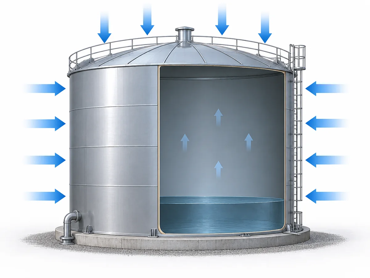
Vacuum collapse is fundamentally an external-pressure problem.
When pressure inside a storage tank falls below the pressure acting outside the tank, the shell and roof must resist the resulting inward pressure differential. If that differential exceeds the actual tank’s structural capability, inward deformation or buckling can occur.
AIChE/CCPS vacuum-hazard guidance treats loss of internal pressure relative to equipment vacuum capability as a collapse hazard, while peer-reviewed storage-tank research likewise analyzes internal vacuum as external-pressure loading on the tank structure. The exact resistance remains tank-specific rather than transferable from one case to another.
Describing this simply as “vacuum sucking the tank inward” hides the engineering issue. The useful relationship is:
external pressure − internal pressure = pressure differential acting across the tank boundary
The tank must remain structurally stable under that differential.
Thin-walled storage tanks can be particularly sensitive to external-pressure loading because buckling resistance depends on more than the material’s basic strength. Tank geometry, shell thickness, structural details, fabrication imperfections, corrosion, thinning and existing damage can all influence the actual resistance to inward buckling.
For that reason, there is no defensible universal vacuum value at which every storage tank will collapse.
A tank designed to operate with some positive internal pressure also should not be assumed to have an equal vacuum capability. Internal-pressure resistance and external-pressure stability are different engineering questions.
For a real installation, the meaningful comparison is therefore:
What pressure differential occurred, and how does it compare with the documented vacuum or external-pressure capability of this specific tank?
If that design basis is unknown, the missing information cannot safely be replaced with a generic “safe vacuum” number.
For background on vacuum mechanisms and process hazards, see
AIChE/CCPS guidance on vacuum hazards.
A recent peer-reviewed storage-tank implosion study also illustrates why structural and operating conclusions from one tank geometry should not be generalized to every tank:
Chemical Engineering & Technology tank implosion study.
What Operating Events Create Dangerous Vacuum in a Storage Tank?
Before inspecting the vacuum valve, identify what was actually driving the tank pressure downward.
Different events produce different inbreathing demands. Treating all of them as the same “vacuum problem” makes it easier to size, troubleshoot or replace the wrong part of the protection system. Related vacuum mechanisms across other equipment are covered separately in ZOBAI’s vacuum service application content.
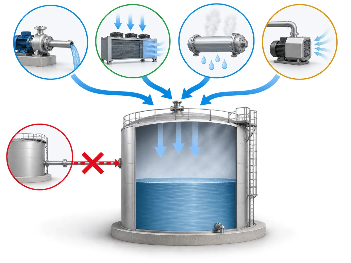
| Operating event | Why tank pressure can fall | What should be verified |
|---|---|---|
| Liquid withdrawal or pump-out | Removing liquid increases vapor-space volume. Gas must enter fast enough to replace that volume. | Actual withdrawal rate and available inbreathing path |
| Cooling of the vapor space | Cooling can contract the gas or vapor and reduce internal pressure. | Temperature history, vapor-space condition and operating state |
| Steam or condensable-vapor cooling | Condensation converts vapor to liquid and can rapidly reduce vapor-phase volume. | Whether relevant condensable vapor was present and how cooling occurred |
| Applied vacuum source | A vacuum pump, eductor or connected process can actively remove gas. | Vacuum source, controls, operating sequence and make-up path |
| Combined events | Withdrawal, cooling, condensation or other mechanisms may act together. | Full process timeline rather than one isolated parameter |
Liquid withdrawal creates an inbreathing requirement
When product is pumped out, the vapor space gets larger. Replacement gas has to enter the tank as that volume increases.
If the incoming gas flow through the protection system cannot keep pace with the actual withdrawal condition, internal pressure can continue falling.
That does not mean every pump-out operation is dangerous. The important comparison is between the actual inbreathing demand and the available installed capacity to admit replacement gas.
Cooling can create vacuum without pump-out
Tank pressure may also fall while the liquid level is unchanged.
Cooling of the vapor space can reduce gas or vapor pressure. Where steam or another condensable vapor is present, condensation can reduce vapor-phase inventory much more rapidly.
AIChE/CCPS process-safety guidance identifies inadequate venting during draining and cooling, steam condensation, and externally imposed vacuum sources as credible vacuum mechanisms. These mechanisms should still be applied only where the actual process conditions support them.
A strong external vacuum source is a separate scenario
A connected vacuum pump, eductor or other system capable of actively removing gas can create a different duty from ordinary tank breathing.
The protection basis must reflect the actual scenario rather than assuming that normal thermal breathing or routine pump-out defines the worst credible vacuum demand.
A blocked vent is usually not the whole explanation
A blocked, covered or fouled vent may explain why pressure could not equalize, but an investigation should still determine what was causing pressure to fall.
Pump-out / cooling / condensation → vacuum demand develops → vent or make-up path unavailable or inadequate → internal pressure continues falling
AIChE/CCPS’s February 2007 Process Safety Beacon on collapsed tanks documents cases involving intended vent paths that were covered or plugged. The engineering lesson is broader than “keep the vent clean”: the pressure-driving event and the failed protection path need to be identified separately.
Why Can Vacuum Protection Fail Even When a Vent or Valve Is Installed?
Seeing a breather valve, pressure-vacuum vent, vacuum-relief valve or blanketing system on a storage tank does not establish that the tank is adequately protected.
Effective vacuum protection requires several different conditions to be satisfied at the same time.
| Protection layer | What can fail | What must be established |
|---|---|---|
| Design basis | The actual pump-out, thermal or abnormal vacuum case was not included in the original basis. | Which scenarios the protection system was designed to handle |
| Opening condition | The device response is not adequately coordinated with the tank’s allowable vacuum. | Actual setting and documented tank limit |
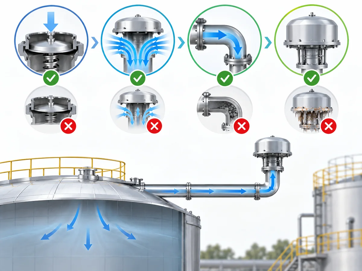
| Flow capacity | The device opens but cannot admit gas fast enough for the actual duty. | Required inbreathing rate versus documented flow performance |
| Installed flow path | Piping, screens, flame arresters or other components introduce excessive restriction. | Complete installed configuration and relevant pressure losses |
| Availability | The path is blocked, covered, isolated, fouled or otherwise unavailable. | Physical configuration during the event |
| Device condition | The installed unit does not function as intended. | Inspection, maintenance or test evidence |
The most important distinction is:
Correct setting ≠ adequate capacity ≠ adequate installed flow path ≠ guaranteed availability.
Within its applicable U.S. scope, OSHA’s storage-tank venting provisions distinguish vent opening pressure, full-open condition and flow capacity rather than treating them as one characteristic. Tank-venting engineering guidance likewise treats tank design vacuum, required flow and device performance as separate selection inputs.
Opening at the right vacuum is not enough
A vacuum-relief device can begin opening at its intended condition and still fail to protect the tank if the required inward gas flow is greater than the flow the system can actually deliver.
Opening condition answers:
When does the device begin responding?
Capacity answers a different question:
Can enough gas pass through the protection system to control the pressure drop?
Those cannot be treated as interchangeable specifications.
Nominal valve size is not installed-system capacity
Device performance is established under defined conditions. The installed protection path may contain additional piping, screens, weather protection, flame arresters, nozzles or other components.
Those components can add resistance. Engineering guidance for tank-protection accessories such as flame arresters therefore treats allowable pressure drop as a separate application input rather than assuming that nominal connection size represents installed-system capacity.
This is why a nominal connection size does not, by itself, establish how much inbreathing protection the complete installation provides.
Required inward flow vs. available flow through the complete installed path
—not merely a comparison of flange sizes.
A protection path must also be physically available
A correctly selected device cannot perform its intended function if replacement gas cannot reach the tank.
During a vacuum-collapse investigation, the physical path therefore matters just as much as the device nameplate:
- Was anything covering the vent?
- Was there fouling or obstruction?
- Could an isolation point interrupt the flow path?
- Had piping or accessories been modified?
- Was the actual installed arrangement the same as the design basis?
These are checks, not predetermined diagnoses.
Blanketing is not automatically a substitute for vacuum relief
Gas blanketing can influence tank pressure, but the existence of a nitrogen or other blanketing system does not by itself prove that every credible inbreathing demand is protected.
The available make-up capacity, pressure-control arrangement and interaction with other protection layers have to be understood for the actual installation.
There is also another process boundary: in some inerted or flammable services, unrestricted admission of atmospheric air may create a separate hazard. Vacuum protection therefore cannot always be simplified to “open the tank to more air.”
The correct protection strategy depends on the process as well as the tank.
For device-level information after the duty has been defined, see ZOBAI’s vacuum safety valves page. This article does not use that product page to infer suitability for any specific tank.
How Should You Investigate a Vacuum Collapse or Near Miss?
A deformed tank is evidence that something went wrong, but it is not a root-cause diagnosis.
A useful investigation moves from the operating event through the complete protection system instead of beginning with the assumption that one valve failed.
The sequence below is an engineering investigation framework for organizing evidence. It is not a universal regulatory checklist, a substitute for a formal incident investigation, or a remote root-cause determination.
1. Reconstruct the actual operating event
Establish what was happening immediately before and during the pressure excursion.
Relevant evidence may include:
- pump or transfer status;
- liquid level changes;
- temperature history;
- cleaning or steaming sequence;
- isolation sequence;
- vacuum-system operation;
- blanketing-system behavior;
- alarms and process trends.
The objective is to rebuild the sequence from recorded evidence rather than from assumptions formed after the tank was damaged.
2. Identify what drove pressure downward
Determine which physical mechanism created the vacuum demand.
Was liquid being withdrawn? Did the vapor space cool? Was steam or another condensable vapor present? Was the tank connected to an active vacuum source?
More than one mechanism may have contributed.
This question should be answered before the vent is declared the cause.
3. Establish the tank’s documented pressure and vacuum basis
Retrieve the actual tank design information.
The relevant question is not whether the tank normally operates near atmospheric pressure. It is what external-pressure or vacuum condition the tank was designed to withstand.
Do not infer this value from:
- tank diameter alone;
- the operating pressure;
- another similar-looking tank;
- an unrelated storage-tank standard;
- the installed vacuum valve setting.
4. Identify the protection that was intended to respond
Determine what was supposed to limit the vacuum:
- a vacuum pallet in a P/V vent;
- a dedicated vacuum-relief device;
- a gas make-up or blanketing arrangement;
- another engineered vent path;
- or a combination of protection layers.
Without knowing the intended architecture, it is impossible to establish whether the system actually performed as designed.
5. Trace the full inbreathing path
Follow the route replacement gas was expected to take into the tank.
Check the actual installation, including relevant:
- vent piping;
- nozzles;
- screens;
- flame arresters;
- isolation points;
- covers or weather protection;
- other accessories.
A valve can be serviceable while the overall path remains unavailable or too restrictive.
6. Inspect the protection device rather than inferring its condition
Verify its configuration, setting and condition from appropriate documentation, inspection and, where applicable, testing.
Do not work backwards from the collapsed tank and treat valve malfunction as already proven.
Device failure is one possible explanation. It is not the only one.
7. Compare the actual duty with installed capability
Once the vacuum-generating scenario is understood, compare that demand with the documented performance of the complete protection path.
This is where three values that are often confused have to remain separate:
- device opening condition;
- required inbreathing flow;
- available installed flow capability.
A satisfactory answer to one does not automatically answer the others.
8. Check whether operating conditions changed
A system originally designed for one duty may become inadequate after a change in:
- pump or transfer rate;
- operating procedure;
- cleaning method;
- tank service;
- blanketing arrangement;
- piping;
- vent accessories.
The investigation should compare current operating conditions with the basis used when the protection was originally specified.
9. Review tank condition as a separate factor
Vent performance is not the only variable.
Corrosion, thinning, previous deformation or other structural deterioration can affect buckling resistance. Structural condition should therefore be investigated separately rather than inferred from the valve condition.
10. Escalate structural and restart decisions appropriately
If the tank has already deformed, neither the condition of the vent nor a replacement valve establishes that the tank remains fit for service.
Remaining structural capacity, repair requirements and return-to-service decisions require appropriate inspection and engineering evaluation.
A technical article can help organize the investigation. It cannot remotely certify the integrity of a damaged tank.
What Must Be Verified Before Changing or Specifying Vacuum Protection?
A replacement vacuum valve should not be chosen simply because it has the same connection size as the old one.
Before specifying new protection, first define:
- the tank;
- the vacuum-generating duty;
- the allowable pressure boundary;
- the complete installed flow path.
Only then does device selection become meaningful.
Information the tank owner or engineer should establish
A useful engineering package includes the information relevant to the actual service, such as:
- tank type and service;
- documented design pressure and vacuum or allowable external-pressure basis;
- stored liquid and relevant vapor behavior;
- normal operating pressure;
- credible liquid withdrawal or transfer rate;
- cooling or condensation case, where applicable;
- any externally imposed vacuum source;
- blanketing or gas make-up arrangement;
- existing pressure/vacuum protection;
- installed piping and relevant accessories;
- applicable project standard, jurisdiction and required edition.
Not every tank needs every scenario. The purpose is to define the cases that are credible for this installation.
The protection-system review should then verify
The engineering or supplier review can evaluate:
- suitability of the proposed protection architecture for the defined service;
- coordination between device opening condition and tank allowable vacuum;
- documented flow performance against the required inbreathing duty;
- impact of installed restrictions;
- material and process compatibility where relevant;
- interaction between blanketing and independent protection layers;
- required inspection, test or project documentation.
Treat standards as engineering frameworks, not generic labels
API Standard 2000 and ISO 28300 are recognized references for venting atmospheric and low-pressure storage tanks, but the applicable scope and edition must be confirmed for the project.
ISO 28300’s published scope is not a blanket rule for every possible stored liquid, and edition status is version-sensitive.
U.S. regulatory requirements are also jurisdiction-specific. For example, OSHA 29 CFR 1910.106 addresses venting associated with filling, emptying and atmospheric temperature changes for applicable flammable-liquid tanks. That regulatory scope should not be rewritten as a universal global rule.
The same discipline applies when an old specification references an older edition of an industry standard: the existence of that historical requirement does not establish the current project basis.
For the wider pressure, vacuum and emergency protection architecture around tanks, see ZOBAI’s storage-tank venting and protection application page.
Specify the duty before specifying the valve
The most useful RFQ is not simply, “Please quote a vacuum valve for this flange size.”
It begins with enough information to answer:
What vacuum condition must be controlled, how much inward flow is required, what limit must the tank stay above, and what restrictions exist between the gas source and the tank?
Connection size, nominal pressure or a photograph of the old vent cannot answer those questions.
Once the duty and system boundary are known, a replacement device or revised protection strategy can be evaluated against the actual tank instead of against assumptions.