了解储罐为何在真空工况下发生失稳塌陷、真空保护系统可能如何失效,以及工程师在变更真空保护方案前应核实哪些事项。

储罐在真空作用下可能发生失稳坍塌,当 罐内压力低于罐外压力达到一定程度,所产生的压差超过储罐实际可承受的外压能力时. 储罐无需接近完全真空,损坏就可能发生。
失效通常以连锁方式发展,而不是单一部件损坏。操作或热工况事件首先产生 补气需求——即随着罐内压力下降,需要气体进入储罐。保护系统随后必须通过可用且足够通畅的通道补入足够气体,在压差达到破坏性程度之前完成。
这意味着储罐坍塌并不自动证明真空阀本身失效。有效的调查应区分三个问题:
- 真空需求是如何产生的?
- 保护系统为何未能控制该需求?
- 储罐结构为何无法承受由此产生的压差?
这些问题被有意分开。第一个是工艺工况问题,第二个是保护系统问题,第三个是储罐完整性问题。将三者视为同一个问题,往往会导致团队更换了呼吸阀,却没有纠正产生真空的工况事件,或者归咎于一台从未按实际工况选型的设备。
真空为何会导致储罐坍塌?
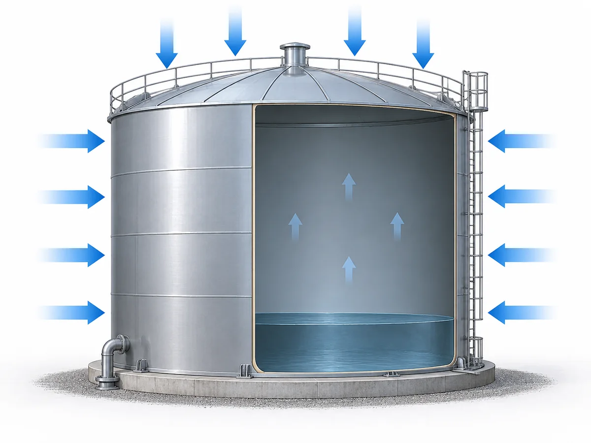
真空失稳本质上是一个 外压问题.
当储罐内部压力低于罐外作用压力时,罐壁和罐顶必须承受由此产生的向内压差。如果该压差超过储罐实际的结构承载能力,就可能发生向内变形或失稳。
AIChE/CCPS 真空危害指南 警告称,按内压设计的设备未必按真空工况设计。同行评审的储罐研究同样将内部真空视为薄壁储罐上的外压载荷,其失稳敏感性受储罐几何形状和状态影响。实际意义在于,压力等级不能替代有据可查的真空或外压承载能力。
将其简单描述为“真空把储罐向内吸”掩盖了工程问题。有用的关系式为:
外压 − 内压 = 作用于储罐边界上的压差
储罐必须在该压差下保持结构稳定。
薄壁储罐对外压载荷可能特别敏感,因为抗失稳能力不仅取决于材料的基本强度。储罐几何形状、罐壁厚度、结构细节、制造缺陷、腐蚀、减薄及既有损伤都会影响实际的向内失稳抗力。一项 2016 年关于内真空条件下地上钢制储罐的同行评审研究 发现腐蚀会显著改变失稳强度和失效模式;这为该机理提供了有用证据,但并非通用的失稳阈值。
因此,不存在一个可辩护的通用真空值能使所有储罐发生失稳。一项 2026 年关于食品储罐内爆的开放获取研究展示了如何将蒸汽冷凝、储罐几何形状和结构建模结合起来分析一起有记录的案例,同时也明确表明该模型取决于该储罐的几何形状和运行历史。该案例证明冷凝驱动的真空可能很严重;但这不是可以照搬到另一台储罐设计依据中的数值。
设计为在有一定正内压条件下运行的储罐,也不应被假定具有同等的真空承受能力。内压承载能力与外压稳定性是两个不同的工程问题。
因此,对于实际安装工况,有意义的比较是:
出现了多大的压差,它与该特定储罐已记录的真空或外压承受能力相比如何?
如果该设计依据未知,则不能用通用的“安全真空”数值来安全地替代缺失信息。应调取储罐数据表、设计图纸或适用的工程计算,并单独评估腐蚀、变形或改造是否可能已改变安装后的实际状态。
工程依据: Chemical Engineering & Technology, 2026,已记录的食品储罐内爆研究.
哪些操作事件会在储罐中产生危险真空?
在检查真空阀之前,应确定 究竟是什么在驱动储罐压力下降.
不同事件会产生不同的补气需求。将它们都视为相同的“真空问题”,更容易导致对保护系统中错误部件进行选型、故障排查或更换。其他设备中相关的真空机理在 ZOBAI 的以下内容中单独介绍: 真空工况 应用内容。
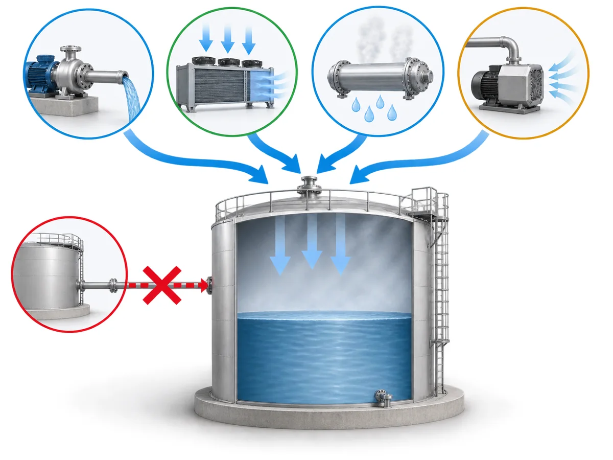
| 工况事件 | 储罐压力为何会下降 | 应核实的内容 |
|---|---|---|
| 液体抽出或泵出 | 抽出液体会增大气相空间体积,气体必须足够快地进入以补充该体积。 | 实际抽出速率、如相关则包括同时抽出情况,以及可用的补气路径 |
| 气相空间冷却 | 冷却会使气体或蒸气收缩,从而降低内部压力。 | 温度历史、气相空间状态、天气或工艺冷却情况,以及运行状态 |
| 蒸汽或可凝蒸气冷却 | 冷凝将蒸气转化为液体,并可能迅速减少气相存量。 | 是否存在相关可凝性蒸气、储罐是否已隔离,以及冷却如何发生 |
| 所施加的真空源 | 真空泵、喷射器或相连工艺可主动抽出气体。 | 真空源、控制方式、隔离逻辑、操作顺序及补气路径 |
| 组合事件 | 抽出、冷却、冷凝或其他机理可能同时作用。 | 完整工艺时间线,而非单一孤立参数 |
液体抽出产生补气需求
当产品被泵出时,气相空间变大。随着该体积增大,必须向储罐内补入气体。
如果通过保护系统的进气流量无法跟上实际抽出工况,内部压力可能持续下降。对于适用的美国易燃液体储罐,, OSHA 29 CFR 1910.106 明确针对因充装、排空及大气温度变化引起的真空或压力所导致的正常通气问题,并要求在可能同时发生充装或抽料的情况下考虑同时流量。该 OSHA 规则具有管辖区域和工况特定性,并非通用的全球设计规则。
这并不意味着每次抽料操作都是危险的。重要的比较在于 实际吸入需求 以及 可用于补入置换气体的已安装通气能力.
示例性工程场景——开启点正确、排量能力不足: 储罐的真空通气口在设定值下开始开启,但后续工艺变更提高了最大抽料速率,而通气设计基准未作相应调整。此时装置可能机械状态完好,却仍无法将储罐压力维持在设计真空度以上,因为所需吸入流量已超过现有已安装通气流量。预防措施是:每当输送速率或同时抽料条件发生变化时,重新核查通气设计基准,而不仅仅是确认整定值。
冷却可在无抽料情况下产生真空
储罐压力也可能在液位不变时下降。
气相空间冷却会降低气体或蒸气压力。当存在蒸汽或其他可凝性蒸气时,冷凝会使气相物料量下降得更快。
AIChE/CCPS 过程安全指南 将排液和冷却期间通气不足、蒸汽冷凝以及外部施加的真空源认定为可信的真空产生机理。这些机理仍应仅在实际工艺条件支持时予以采用。
有记录的工程实例——蒸汽吹扫后冷却: AIChE/CCPS 将蒸汽吹扫描述为一种真空危害,因为如果设备未充分放空,蒸汽会迅速冷凝。2026 年同行评审的食品储罐研究将一起有记录的瘪罐事故与清洗后的冷却和蒸汽冷凝联系起来。教训不是照搬该储罐的压力历史,而是将蒸汽吹扫、隔离状态和冷却视为一个独立的真空工况,其补气基准可能与常规抽排不同。
强外部真空源是独立工况
连接真空泵、喷射器或其他能够主动抽气的系统,可能产生与常规储罐呼吸不同的负荷。
防护基准必须反映实际工况,而不能假设正常热呼吸或常规抽排定义了最严苛的可信真空需求。如果真空源的抽压速度快于补气或泄放路径的响应速度,正确的工程问题是:储罐是否按该真空条件设计,或者系统是否提供了确实可用的限真空手段。
放空口堵塞通常不是全部原因
放空口堵塞、被遮盖或污堵可能解释 why pressure could not equalize, but an investigation should still determine what was causing pressure to fall.
Pump-out / cooling / condensation → vacuum demand develops → vent or make-up path unavailable or inadequate → internal pressure continues falling
AIChE/CCPS’s February 2007 Process Safety Beacon on collapsed tanks documents cases involving intended vent paths that were covered or plugged. The engineering lesson is broader than “keep the vent clean”: the pressure-driving event and the failed protection path need to be identified separately.
Why Can Vacuum Protection Fail Even When a Vent or Valve Is Installed?
Seeing a breather valve, pressure-vacuum vent, vacuum-relief valve or blanketing system on a storage tank does 不 establish that the tank is adequately protected.
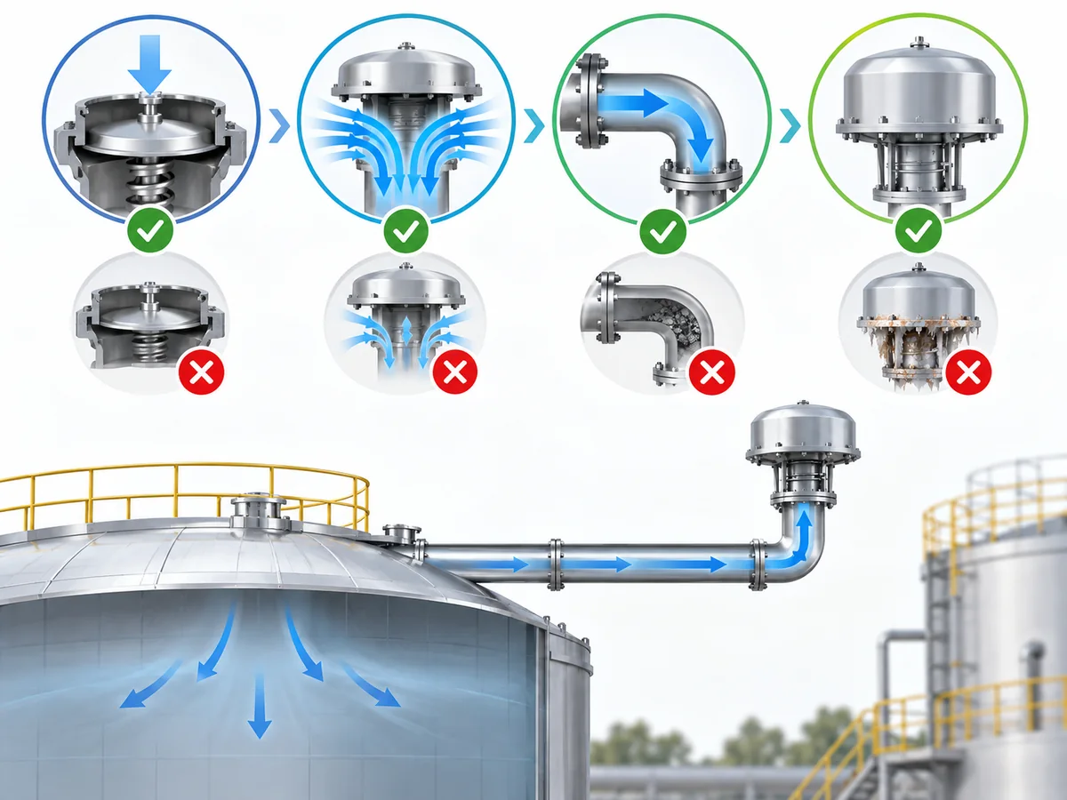
Effective vacuum protection requires several different conditions to be satisfied at the same time. A device can have the intended opening setting yet still be inadequate because the required inbreathing capacity was underestimated, the installed path adds more resistance than the sizing basis assumed, the path is unavailable, or the process has changed.
| Protection layer | What can fail | 必须确定的内容 |
|---|---|---|
| Design basis | The actual pump-out, thermal or abnormal vacuum case was not included in the original basis. | Which scenarios the protection system was designed to handle |
| Opening condition | The device response is not adequately coordinated with the tank’s allowable vacuum. | Actual setting and documented tank limit |
| Flow capacity | The device opens but cannot admit gas fast enough for the actual duty. | Required inbreathing rate versus documented flow performance |
| 实际安装后的流通路径 | Piping, screens, flame arresters or other components introduce restriction. | Complete installed configuration and pressure losses relevant to the duty |
| Availability | The path is blocked, covered, isolated, fouled or otherwise unavailable. | Physical configuration during the event |
| Device condition | The installed unit does not function as intended. | Inspection, maintenance or test evidence |
The most important distinction is:
Correct setting ≠ adequate capacity ≠ adequate installed flow path ≠ guaranteed availability.
This separation is also reflected in tank-venting guidance. Manufacturer vent-sizing guidance treats tank design vacuum, vent set point, required flow and vent flow capability as separate inputs. The source is useful for device/application mechanics; the applicable code basis and final duty still have to come from the project.
Opening at the right vacuum is not enough
A vacuum-relief device can begin opening at its intended condition and still fail to protect the tank if the required inward gas flow is greater than the flow the system can actually deliver.
Opening condition answers:
When does the device begin responding?
Capacity answers a different question:
Can enough gas pass through the protection system to control the pressure drop?
Those cannot be treated as interchangeable specifications. A capacity check must use the credible inbreathing case and the documented performance basis for the device or system; connection size alone does not establish capacity.
Nominal valve size is not installed-system capacity
Device performance is established under defined conditions. The installed protection path may contain additional piping, screens, weather protection, flame arresters, nozzles or other components.
Those components can add resistance. The engineering comparison is therefore between required inward flow 和 available flow through the complete installed path at an acceptable tank pressure, not merely between two flange sizes.
Required inward flow vs. available flow through the complete installed path
示例工程场景——在原定尺寸计算之后增设的附件: 储罐呼吸口最初是按转料工况选型的,采用短而低阻力的流通路径。之后加装了阻火器或其他呼吸管路附件,或原有元件发生堵塞。阀门本身公布的流通能力并未改变,但实际安装路径的压降已经改变。正确的做法是依据储罐允许真空度和所需吸入流量复核整条路径,而不是想当然认为现有公称通径的阀门仍然适用。.
防护路径还必须在物理上畅通可用
如果补充气体无法到达储罐,即使设备选型正确也无法发挥其预期功能。.
因此,在真空失稳(瘪罐)事故调查中,实际物理路径与设备铭牌同样重要:
- 呼吸口是否被任何物体遮盖?
- 是否存在堵塞、沉积、杂物、结冰或其他与该工况相关的阻碍?
- 是否存在可能中断流通路径的隔离点?
- 管路、阻火防护附件或其他附件是否经过改动?
- 实际安装布置是否与设计依据一致?
这些是检查项,而非预设结论。储罐瘪塌并不能证明真空阀的运动部件卡滞;它也可能表明所需流量从未通过假定路径到达设备或储罐。.
充氮保护并不自动等同于真空泄放
氮封可能影响储罐压力,但氮气或其他氮封系统的存在本身并不能证明所有可信的吸入需求都得到了保护。.
必须针对实际安装情况,了解可用的补充能力、供气压力、压力控制布置以及与其他保护层的相互作用。当前制造商的储罐管理架构通常将氮封、压力/真空泄放、火焰防护和紧急泄放作为独立的保护层,而非可互换的功能。.
示例工程场景——氮封被赋予超出其已验证能力的职责: 氮封调节阀在常规呼吸过程中维持微正压,因此设计团队假定它也能覆盖最大抽料工况。如果可信的抽料速率超过调节阀及供气系统已证实的补充能力,储罐压力仍可能下降至真空泄放整定值。预防措施是明确氮封承担什么职责、独立真空泄放承担什么职责,以及两者在同一事件中是否均保持可用。.
还存在另一个工艺边界:在某些惰化或易燃工况中,无限制地引入大气空气可能产生单独的危险。AIChE/CCPS 特别指出,真空可能将空气吸入易燃设备。因此,真空保护不能总是简化为“向储罐引入更多空气”。”
正确的保护策略取决于工艺以及储罐。.
在确定职责后,如需了解设备层面的信息,请参阅 ZOBAI 的 真空安全阀 页面。本文不使用该产品页面来推断对任何特定储罐的适用性。.
如何调查真空失稳或未遂事件?
储罐变形是出现问题的证据,但不是根本原因诊断。.
有效的调查应从操作事件出发,贯穿整个保护系统,而不是从假定某一个阀门失效开始。.
以下流程是用于组织证据的工程调查框架,并非通用法规检查清单,不能替代正式的事故调查,也不构成远程根本原因判定。.
1. 还原实际运行事件
确定压力异常发生前及发生期间的实际运行状态。.
相关证据可包括:
- 泵或输送状态及实际抽液速率;;
- 液位变化;;
- 温度历史记录;;
- 清洗或蒸汽吹扫顺序;;
- 隔离顺序;;
- 真空系统运行情况;;
- 覆盖系统行为及供气可用性;;
- 报警及工艺趋势;;
- 可能改变排放通路的维护或改造作业。.
目标是根据记录证据重建事件序列,而不是依据储罐受损后形成的假设。.
2. 确定导致压力下降的因素
确定是哪种物理机制产生了真空需求。.
是否有液体被抽出?气相空间是否冷却?是否存在蒸汽或其他可冷凝蒸气?储罐是否连接到有效的真空源?
可能有多种机制共同作用。不得用排放口堵塞替代本步骤:堵塞可以解释储罐为何无法呼吸,但仍须确定导致压力变化的事件。.
在判定排放口为原因之前,应先回答这一问题。.
3. 确定储罐有据可查的压力和真空基准
调取实际的储罐设计资料。.
关键问题不是储罐是否通常在接近大气压下运行,而是储罐设计用于承受何种外压或真空条件,以及后续改造或劣化是否可能改变了竣工状态。.
不得根据以下信息推断该值:
- 仅储罐直径;;
- 工作压力;;
- 另一台外观相似的储罐;;
- 一项无关的储罐标准;;
- 已安装真空阀的设定值。.
4. 确定原本应作出响应的保护措施
确定原本应由什么来限制真空:
- P/V 呼吸阀中的真空阀片;;
- 专用真空泄放装置;;
- 补气或惰化保护措施;;
- 另一条工程设计的泄放路径;;
- 或多种保护措施的组合。.
在不了解原设计架构的情况下,无法确定系统是否确实按设计运行。.
5. 追溯完整的吸入路径
沿补气气体预期进入储罐的路线进行排查。.
检查实际安装情况,包括相关:
- 放空管道;;
- 接管;;
- 滤网;;
- 阻火器;;
- 隔离点;;
- 防护罩或防风雨保护;;
- 其他附件。.
阀门本身可能仍可使用,但整体路径仍可能不通或阻力过大。.
6. 检查保护装置本身,而非推断其状态
Verify its configuration, set condition and physical condition from appropriate documentation, inspection and, where applicable, testing.
Do not work backwards from the collapsed tank and treat valve malfunction as already proven.
Device failure is one possible explanation. It is not the only one. If the device is dismantled or serviced as part of the investigation, preserve the relevant as-found observations and records so that maintenance activity does not erase evidence needed to explain the event.
API 现行标准计划 lists RP 575, Inspection Practices for Atmospheric and Low-Pressure Storage Tanks, 以及 RP 576, Inspection of Pressure-relieving Devices as current API documents, with recent 2025–2026 addenda. Use the editions required by the project or jurisdiction; this article does not prescribe a fixed inspection interval.
7. Compare the actual duty with installed capability
Once the vacuum-generating scenario is understood, compare that demand with the documented performance of the complete protection path.
This is where three values that are often confused have to remain separate:
- device opening condition;
- required inbreathing flow;
- available installed flow capability.
A satisfactory answer to one does not automatically answer the others. If the vent has a documented flow curve, the relevant comparison is the flow available before the tank’s allowable vacuum is exceeded under the actual installed conditions.
8. Check whether operating conditions changed
A system originally designed for one duty may become inadequate after a change in:
- pump or transfer rate;
- operating procedure;
- cleaning method;
- tank service or stored fluid;
- blanketing arrangement or gas supply;
- piping;
- vent accessories.
The investigation should compare current operating conditions with the basis used when the protection was originally specified. A change in process duty can invalidate a once-adequate venting basis even when the valve itself has not changed.
9. Review tank condition as a separate factor
Vent performance is not the only variable.
Corrosion, thinning, previous deformation or other structural deterioration can affect buckling resistance. Structural condition should therefore be investigated separately rather than inferred from the valve condition.
10. Escalate structural and restart decisions appropriately
If the tank has already deformed, neither the condition of the vent nor a replacement valve establishes that the tank remains fit for service.
Remaining structural capacity, repair requirements and return-to-service decisions require appropriate inspection and engineering evaluation under the applicable tank-integrity framework.
A technical article can help organize the investigation. It cannot remotely certify the integrity of a damaged tank.
What Must Be Verified Before Changing or Specifying Vacuum Protection?
A replacement vacuum valve should not be chosen simply because it has the same connection size as the old one.
Before specifying new protection, first define:
- the tank;
- the vacuum-generating duty;
- the allowable pressure boundary;
- the complete installed flow path.
Only then does device selection become meaningful.
Information the tank owner or engineer should establish
A useful engineering package includes the information relevant to the actual service, such as:
- tank type, construction and service;
- documented design pressure and design vacuum or allowable external-pressure basis;
- stored liquid and relevant vapor behavior;
- 正常工作压力;;
- maximum credible liquid withdrawal or transfer rate, including simultaneous cases where applicable;
- cooling or condensation case, where applicable;
- any externally imposed vacuum source;
- blanketing or gas make-up arrangement and available supply capacity;
- existing pressure/vacuum protection and its documented setting/capacity information;
- installed piping, flame arresters, screens and other relevant accessories;
- applicable project standard, jurisdiction and required edition.
Not every tank needs every scenario. The purpose is to define the cases that are credible for this installation, then establish which case governs the inbreathing requirement.
The protection-system review should then verify
The engineering or supplier review can evaluate:
- suitability of the proposed protection architecture for the defined service;
- coordination between device opening condition and tank allowable vacuum;
- documented flow performance against the required inbreathing duty;
- impact of installed restrictions and accessories;
- material and process compatibility where relevant;
- interaction between blanketing and independent protection layers;
- whether atmospheric air admission is acceptable for the process;
- required inspection, test and project documentation.
Illustrative procurement failure — selecting by flange size: A replacement vent is ordered with the same nozzle connection as the removed unit, but the old rating basis, actual inbreathing duty and installed accessory pressure loss are not checked. The new device may physically fit and still be the wrong protection. A defensible RFQ therefore starts with the tank design vacuum, governing inbreathing scenario and required capacity—not the connection size.
Treat standards as engineering frameworks, not generic labels
API 现行标准计划 lists API Standard 2000, Venting Atmospheric and Low-Pressure Storage Tanks, 8th Edition. ISO 28300:2008 remains the published current ISO edition, while ISO shows a second edition under development. Those references address tank venting, but the project must still confirm the applicable scope, edition and contractual or regulatory basis.
ISO 28300:2008 is written for petroleum and petroleum-product storage tanks and states that application to other liquids requires sound engineering analysis and judgment. It also excludes external floating-roof tanks. That scope matters: citing the standard name is not the same as proving that every storage tank on every service falls within it.
U.S. regulatory requirements are also jurisdiction-specific. OSHA 29 CFR 1910.106 requires adequate normal venting for applicable flammable-liquid storage tanks so filling, emptying and atmospheric temperature changes do not create damaging pressure or vacuum. Its incorporated API Standard 2000 reference is the 1968 edition, so it should not be described as if OSHA automatically incorporates the current API edition.
The same discipline applies when an old datasheet or facility specification cites a legacy standard: establish the actual project basis before converting a historical reference into a current compliance claim.
For the wider pressure, vacuum and emergency protection architecture around tanks, see ZOBAI’s storage-tank venting and protection 应用页面。
Specify the duty before specifying the valve
The most useful RFQ is not simply, “Please quote a vacuum valve for this flange size.”
It begins with enough information to answer:
What vacuum condition must be controlled, how much inward flow is required, what limit must the tank stay above, and what restrictions exist between the gas source and the tank?
Connection size, nominal pressure or a photograph of the old vent cannot answer those questions. A supplier can only verify capacity, setting and construction against the duty that the owner or engineer actually defines.
Once the duty and system boundary are known, a replacement device or revised protection strategy can be evaluated against the actual tank instead of against assumptions.
Frequently Asked Questions About Storage Tank Vacuum Collapse
What causes a storage tank to collapse under vacuum?
A tank can buckle when internal pressure falls below external pressure far enough that the resulting pressure differential exceeds the tank’s actual external-pressure capability. The pressure drop may be driven by pump-out, cooling, condensation or an applied vacuum source, while inadequate or unavailable inbreathing allows the differential to grow.
Can a storage tank collapse even if a vacuum relief valve is installed?
Yes. Device presence does not prove adequate protection. The opening condition, required inbreathing capacity, installed-path pressure loss, availability of the flow path and actual device condition all have to be compatible with the tank’s allowable vacuum and credible operating cases.
Is a blocked vent enough to explain a tank implosion?
Not by itself. A blocked vent can prevent pressure equalization, but the investigation still needs to identify what was driving pressure downward—such as liquid withdrawal, cooling, condensation or an active vacuum source. The demand event and the failed breathing path are separate parts of the failure chain.
Does nitrogen blanketing replace a vacuum relief valve?
Not automatically. Blanketing can supply make-up gas and control tank pressure, but its capacity and availability must be proven for the assigned duty. Many tank-protection arrangements use blanketing together with pressure/vacuum relief rather than treating them as interchangeable functions.
Why is vent capacity more important than matching the old connection size?
Connection size only describes a physical interface. Protection depends on the gas flow that the complete installed path can pass before the tank’s allowable vacuum is exceeded. A same-size replacement can therefore be inadequate if the process duty, setting, flow curve or system resistance differs from the original basis.
What should be checked before a deformed tank is returned to service?
A replacement vent alone does not establish fitness for service. The event should be investigated, the tank’s design basis and structural condition should be reviewed, and appropriate inspection and engineering evaluation should determine repair and return-to-service requirements under the applicable tank-integrity framework.